
Solutions in this chapter:
Pneumatics is the discipline that describes gas flow and how to use the properties of gas to transmit energy or convert the same into force and motion. Most pneumatic applications use that gaseous mixture most widely available—air—and the LEGO world is no exception.
Pneumatics is a great tool for robotics, and is especially useful when your mechanisms need linear motion or an elastic behavior. It’s also a very functional way to store energy for subsequent uses. We will briefly cover the basic concepts of pneumatics, and then put those theories into practice, explaining how LEGO pneumatic components work and what you can do with them, and along the way showing you how to stop and start airflow in order to produce motion in your robot. By the end of the chapter, you should be up to speed on many pneumatic components, including valves, pumps, cylinders, compressors, and pneumatic engines.
To understand pneumatics, you have to recall the properties of gases. The most important property is that gases have neither specific shape nor volume, because they expand and fill all available space within a container. This means the quantity of gas inside a tank does not solely depend on the tank’s volume. The greater the quantity of gas in a given volume, the higher its pressure.
Note
The science that describes the properties of gases is called thermodynamics. Its Ideal Gas Law relates four quantities: volume, pressure, temperature, and I mass (expressed in moles). In our simplified discussion, we will deliberately ignore temperature because, in our situation, it shall essentially remain constant throughout.
We all have the opportunities to experiment with pneumatics using everyday objects. The tires of a bicycle are a good example: Their inner volume is constant, but you can increase their pressure by pumping air in. The more air inside, the greater the pressure, and the more it opposes external forces—in other words, the tires become “harder.”
This example leads to a second important property of compressed gases: their pushing outward on the walls of their containers illustrates their elasticity. Elasticity is the property of an object that allows it to return to its original shape after deformation. The greater the elasticity, the more precisely it returns to its original configuration. In the example of the bicycle tire, if you push your finger against it, you can temporarily create a dimple in the surface, but as soon as you remove your finger, the tire resumes its shape—the greater the pressure inside, the higher the resistance to deformation.
The fact that gases are so easy to compress is what makes pneumatics different from hydraulics(the science of liquid flow). Essentially, liquids are uncompressible.
When you compress a gas into a tank, increasing its pressure, you are essentially storing energy. Pressure can be interpreted also as a density of energy, that is, the quantity of energy per unit volume. This leads to a very interesting application of pneumatics: You can use tanks to accumulate energy, which can be released later when needed. You pump gas in to increase the pressure in the tank, storing energy, and you draw gas out to use that energy, converting it into motion.
A flow of air or gas in general is produced by a difference in pressure: The air flows from the container with the higher pressure into the one with the lower pressure, until the two equalize. (In this context, we’ve giving the term container the widest possible meaning. It can be a tank, a pipe, or the inner chambers of a pump or cylinder.)
LEGO introduced the first pneumatic devices in the TECHNIC line during the mid-1980s, and then a few years later modified the system to make it more complete and efficient. The TECHNIC line has a long tradition of impressive pneumatic sets, including trucks, cranes, excavators, and bulldozers.
The basic components of the LEGO pneumatic systems are pumps and cylinders(see Figure 10.1). The function of a pump is to convert mechanical work into air pressure. Pumps come in two kinds: the large variety, designed to be used by hand, and its smaller cousin, suitable for operation with a motor. Cylinders, on the other hand, convert air pressure back into mechanical work, and come in two different sizes as well.
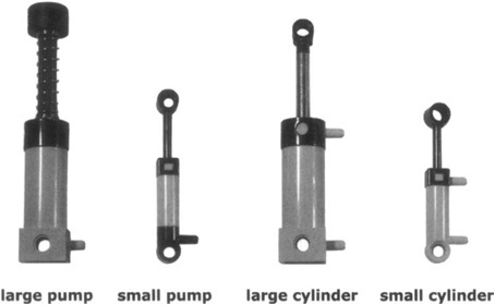
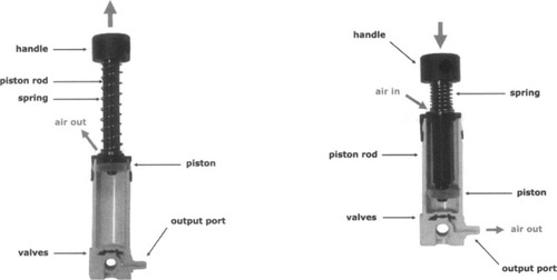
Figure 10.2 shows a cutaway of the large pump in action. When you press its piston down, you reduce the volume of the interior section, thus increasing the pressure and forcing air to exit the output port until the inner pressure equals that outside. When you release the piston, the spring pushes the piston up again; a valve closes the output port so as not to let the compressed air come back inside the pump, while another valve lets new air come in around the piston rod. The small pump follows the same working scheme exactly, with the difference being that it doesn’t contain a spring and its piston needs to be pulled after having been pushed. It’s designed to be operated through an electric motor.
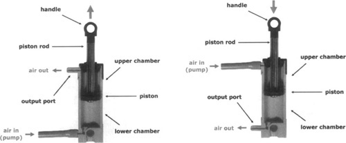
Cylinders are slightly different from pumps. A cylinder’s top is airtight and doesn’t let air escape from around the piston rod. The piston divides the cylinder into both a lower and an upper chamber, each one provided with a port. The basic property of a pneumatic cylinder is that its piston tends to move according to the difference in pressure between the chambers, expanding the volume of the one with higher pressure and reducing the other until the two pressures equalize, or until the piston comes to the end of its stroke. When you connect the lower port to a pump using a tube, and supply compressed air into the lower chamber, its pressure pushes the piston up. Doing this, the volume of the chamber increases, and this lowers the pressure until it’s equal to that of the upper chamber. During the operation, the port of the upper chamber has been left open, so its air can freely escape, reaching equilibrium with the outside air pressure. Similarly, when you connect the upper port to the pump, and supply compressed air, the piston moves down (see Figure 10.3).
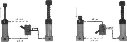
Surely you don’t want to move the tube from one port or the other to operate the cylinder: It may work, but it’s not very practical. The LEGO valve has been designed precisely for this task: It can direct the airflow coming from a pump to either one of the two ports of a cylinder, while at the same time let the pressure from the other chamber of the cylinder discharge into the atmosphere (see Figure 10.4). The valve also has a central (neutral) position, which traps the air in the system so that the cylinder can move neither up nor down.
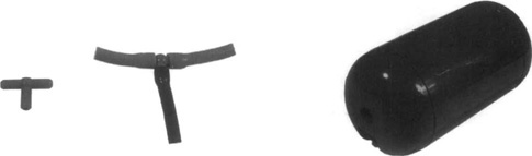
The LEGO tubing system is completed by a T-junction and a tank(see Figure 10.5). T-junctions allow you to branch tubes, typically to bring air from the source to more than a single valve. The tank is very useful for storing a small quantity of compressed air to be used later. We explained that increasing pressure is like storing energy; thus, the air tank can be effectively considered an accumulator: Charge it with compressed air and release it through the valve when necessary to convert that energy into mechanical work.
Pneumatic cylinders provide high-power linear motion, and thus are the ideal choice for a broad range of applications: articulated arms or legs, hands, pliers, cranes, and much more. In describing the basic concepts of pneumatics, we told you that compressed gases tend to make their containers react elastically to external forces. You can test this property with LEGO cylinders, too: Connect a cylinder to a pump and operate the pump until the piston of the cylinder extends in full. Now, press the rod of the cylinder. You can push it down, but as soon as you stop applying force, the rod comes back up again. This property is quite desirable in many situations.
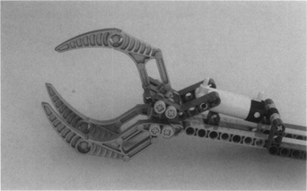
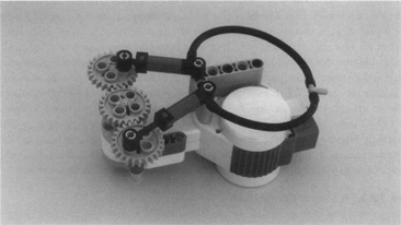
Let’s suppose you’re going to build a robotic hand. If you try to use an electric motor to open and close the hand, you must somehow know when to stop it. To do this, you can use some kind of sensor as a feedback control system that tells your NXT the object has been grabbed and the motor can be stopped. However, a pneumatic cylinder, in most cases, needs no feedback. The air pressure closes the hand until it encounters enough resistance to stop it. This approach works in a wide variety of objects (if your robot is designed to hold eggs, make sure it exerts a very gentle pressure!). Figure 10.6 shows a simple pneumatic hand. You see that we used a scissorlike setup that gives our hand a rather large range in regard to the size of the things it can handle.
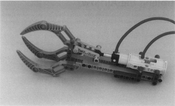
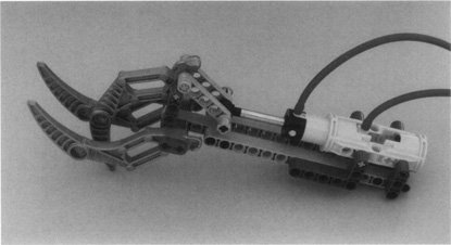
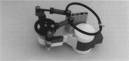
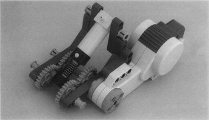
The pneumatic hand shown in Figures 10.7 and 10.8 opens even wider and closes even tighter than the one shown in Figure 10.6. To achieve this wider range of motions we fixed the cylinder so that it remains parallel to the long beams. The parts that enclose the cylinder and keep it parallel to the beams are called cylinder brackets. They are designed mainly for attaching two cylinders back-to-back to obtain a longer linear motion than what’s possible with a single cylinder, but it also works well as a way to prevent a cylinder from rotating.
The preceding example gives you an idea of what pneumatics can be used for. Likely, you’re already imagining other interesting applications. Unfortunately, the LEGO pneumatic system was not designed to be electrically controlled, so to effectively use it in your robotic projects you need an interface that allows your NXT to open and close valves. And unless you plan to run behind your robot pumping like crazy, you probably want to provide it with an automatic compressor.
Industrial pneumatic controllers usually operate valves using solenoids, which are electromagnets that can pull or push valves. LEGO has not released solenoids, but we can use a motor to actuate a valve.
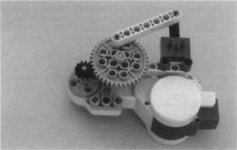
Figure 10.9 shows one of many possible solutions: The motor turns a 12t gear, which turns a 40t gear. When the 40t gear turns, it moves a beam that pulls or pushes the valve. We exploit here the capability of the NXT motor to turn a specific angle. To move the valve from the center position to either extreme, we turn the motor 180 degrees. To return to the center, we turn the motor 180 degrees in the opposite direction.
This electric valve is not very compact, but there’s not much more you can do considering the size of the motor. Just the same, it works well, and you may feel satisfied with it. But could you make something better? Try applying some of the tricks you learned in previous chapters. For example, you know you can control more than one valve with a single motor. You have seen that, using a differential, it’s possible to separate the two turning directions of a motor on two different axles. Now you only need to connect each axle to a valve so that the valve cycles between its positions using only one turning direction. You can do this using a liftarm as a connecting rod; like in old steam locomotives (see Figure 10.10). We used a bent liftarm as a connecting rod because the distance between its extreme holes is about 6.5 LEGO units, a fractional distance that cannot be achieved with a straight beam.
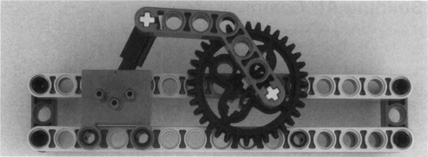
Figure 10.11 shows a prototype of a complete double-electric valve, which combines two setups like those of Figure 10.10 with a motor and a differential gear. This mechanism requires a lot of torque to be operated, but the NXT motor has enough torque to operate it without additional gearing. The differential splits the power onto two 36t gears, each one featuring a ratchet beam that lets it rotate only in a specific direction. Thus, when the motor turns clockwise, one valve moves, and if it turns counterclockwise, the other does, each one cycling between all positions.
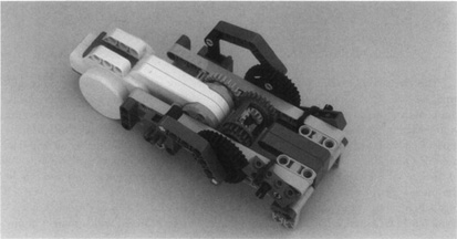
As in Figure 10.9, the servo motor can move the valves accurately from one position to another by turning a specific number of degrees. The fact that the NXT motors include high-resolution encoders allows the motors to easily and precisely operate mechanisms that require accuracy, like the pneumatic valves.
Now that you have discovered a way to operate pneumatic cylinders from your NXT, the next step is to provide them with a good supply of compressed air. Some applications require only a small quantity of air for each motion, in which case you have the option to preload a tank by pumping it manually before you run the robot. A good example is a robot that blows out a candle: All it has to do is find the candle in the room, and then release its air supply to blow it out. You can extend the range using more tanks, but for most practical applications, you will need something more substantial: an unlimited source of compressed air.
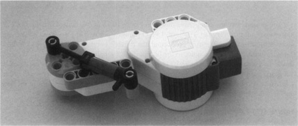
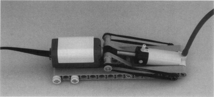
You can achieve this goal easily by building an electric compressor, such as the one shown in Figure 10.12. The small pump is connected to an NXT motor and to an L-shaped liftarm using frictionless pins. The liftarm is mounted directly onto the motor. This compressor is probably the smallest you can build with the NXT motor. There are many possible setups, but it’s very important that you design yours to take advantage of the entire stroke of the pump, because this will make it more efficient. In fact, if your compressor, for example, uses half of the stroke of the pump, it will release only half the maximum quantity of air it could potentially release. When extended, the small pump is two LEGO units longer than when it is retracted; the distance between opposing holes on the NXT motor’s orange shaft is two LEGO units. Thus, the geometry is perfect—if there is a motor position in which the pump is fully retracted, when the motor rotates 180 degrees the pump is extended by exactly two units to its full extension. The only remaining issue, which the L-shaped liftarm takes care of, is to ensure that the pump is fully retracted at some motor position.
A double-acting compressor uses two pumps to provide more airflow. While one of the pumps is pumping, the other takes air, thus providing continuous airflow. Figure 10.13 shows one design, which was inspired by Ralph Hempel’s compressor (his used an older LEGO motor). Three 24t gears are mounted on a beam, which is attached to the motor using a 2 × 4 L-shaped liftarm. The motor rotates the center gear, and two pumps are connected to the outer gears. Note that the pumps are mounted such that when one is fully extended, the other is completely retracted. This ensures that one of the pumps is supplying air almost all the time.
You can improve the compressor shown in Figure 10.13 in two ways. First, the NXT motor does not turn very fast. The small LEGO pumps work well at high speed, so you can increase the air supply by gearing up. Second, the distance between opposing holes on the 24t gears is smaller than two units, so the pumps do not supply all the air they can in each stroke. The variant shown in Figure 10.14 fixes both problems. A 36t gear turns two smaller 12t gears, increasing the speed of the compressor by a factor of three. Also, the two thin 2 x 1 liftarms that push and pull the pumps provide the maximal stroke length (pairs of medium pulleys will achieve exactly the same effect).
You also can use the large pump to build compressors, but they will be less efficient and bulkier than compressors that use the small pump. The compressor shown in Figure 10.15 is inspired by a design by Christopher R. Smith. The large pump requires much more force to operate, so it must be mounted securely in a stiff structure to avoid twisting. This is usually achieved by using gears on both sides of the pump, as we have done here. If you remove the spring, the compressor will run a bit more smoothly and the stroke can be longer, but the compressor works even if you leave the spring in place.
The direction of turning is completely irrelevant to compressors: You can always turn the motor that operates the compressor in the same direction. This opens the possibility of operating a compressor and controlling a valve with a single servo motor. To do so, we would replace one valve in the direction-separation mechanism shown in Figure 10.11 with a compressor, such as the one shown in Figure 10.15. Because of the ratchets, the operation of the compressor is somewhat noisy and inefficient (the motor needs not only compressed air, but also to stretch the rubber bands, which perform no useful work when they shrink back). Therefore, the large pump would work in this setup better than the small pump, because it compresses more air in each stroke.
The nice thing about compressors is that they don’t need to be wired to one of the precious output ports of your NXT: A battery box is enough to run them. If you use the NXT motor with a battery box, you will need a converter cable, or you can use a battery box and some other LEGO motor. You can easily adapt the compressors shown in this chapter to use the RC Buggy motor, and there are also good compressor designs for older LEGO motors.
But you might wonder when you should stop your compressor, and how. The simplest option is not to stop it. Instead, you can place a torque-limiting component in the gearing, such as a pulley or a clutch gear, so that when the pressure reaches a given level, the gearing idles. Figure 10.6 shows a much more elegant solution. Rubber bands pull a cylinder in. When the pressure builds up in the bottom inlet of the cylinder, it pushes the cylinder out. Eventually the cylinder presses the touch sensor. When pressure drops, the rubber bands pull the cylinder back in, releasing the touch sensor. The NXT uses the input from the touch sensor to start and stop the compressor. We have essentially constructed a simple pressure sensor. By adjusting the number and strength of the rubber bands, you can set your pressure switch for the desired pressure threshold. The mechanism shown in Figure 10.16 is loosely based in a design by Ralph Hempel.
Another option is to use a genuine pressure sensor that uses a pressure-sensing electronic chip. An NXT pressure sensor is available from Mindsensors, but we have also successfully built homemade ones.
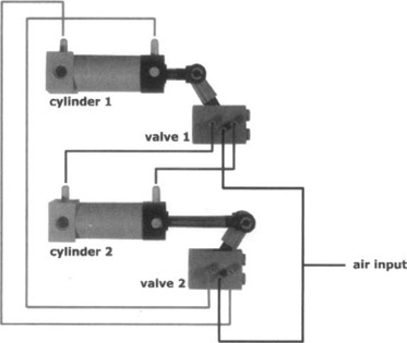
We mentioned before that you can make cylinders control other cylinders. You accomplish this by making a cylinder operate the valve that controls a second cylinder. This is not useful in itself, but you can make a cylinder do something and move a valve. A very interesting case is one in which you connect two cylinders in a loop where each one controls the other, resulting in an unstable system that continuously, and automatically, changes its state (see Figure 10.17). Provided that you have a supply of compressed air, you can take advantage of this feature to make your robot perform an action.
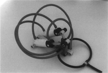
Figure 10.18 shows a diagram of this pneumatic circuit. Cylinder 1 operates valve 1, which controls cylinder 2, which operates valve 2, which controls cylinder 1!
Probably the first robot based on this system to appear publicly on the Internet was Bert van Dam’s pneumatic insect. Figure 10.19 shows our slightly modified replica.
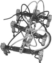
The complicated tubing hides the same basic circuit shown in Figure 10.16—one of the control cylinders moves the three leg assemblies forward and backward, while the other moves the legs up and down. These are made of six cylinders, split into two groups of three, controlled by the same valve. Each group has a leg in a central position on one side, and one leg front and one leg rear on the other side (see Figure 10.20).
Though rather complicated to build, and more academic an example than practical, van Dam’s insect is quite amazing to see in action.
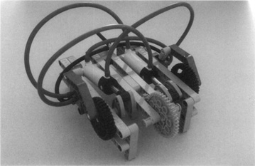
When you use the same principle, it’s possible to build a true pneumatic engine, where the push of the cylinders is converted into rotary motion exactly like in steam engines. Figure 10.21 shows our implementation of a LEGO pneumatic engine designed by C. S. Soh (whose Web site contains a wealth of information on LEGO pneumatics, including fascinating performance measurements of various compressors). The key points about this engine are:
Each cylinder has a dead point in its cycle, when it is either fully extended or retracted. In this position, the cylinder is not able to perform any work, as its push/pull force cannot be converted into rotary motion. This happens because the two connection points of the cylinder (on the chassis and the wheel) and the fulcrum of the wheel align along the same line. For this reason, a pneumatic engine with a single cylinder would not work. The addition of a second cylinder solves the problem: You must mount it with a difference of 90 degrees in its phase against the first one, so when one reaches a dead point, the other is at midstroke.
The phasing of the valves is very important: You must take care to position them precisely; otherwise, your engine won’t work. Mount the 36t gears on the axles in such a way as to align one of their holes with the holes on the cams. Attach the liftarms to that hole with a gray pin. Connect the tubing exactly as shown in Figure 10.21.
Pneumatic engines are capable of high torque, but due to their intrinsic friction they are not suitable for high-speed applications. Most of the friction comes from the cylinders themselves, which, in order to be airtight, are a bit stiff to move.
Generally speaking, a vehicle moved by this engine, and supplied by an onboard compressor, is not very efficient. But it’s indeed fun to see in action and might have its special uses, too.
Beyond the fascinating sight of all those tubes, and the dramatic hissing of the air coming out of the valves, pneumatics has its practical strong points. In this chapter, you reviewed some basic concepts about the properties of gases, and learned how to exploit these when building your robots. Cylinders are definitely a better choice than electric motors for performing particular tasks and, most significantly, have the capability to grab objects and create linear motion.
Electric compressors can provide a constant airflow to supply your cylinders, and can be used to control this flow from the NXT. Unfortunately, interfacing pneumatics to the NXT is not so simple, and requires a bulky assembly that includes an electric motor and some gearing. Perhaps in the future, the LEGO Company will produce a smart and compact interface capable of controlling many valves from a single output port.
Pneumatics also offers the opportunity to implement simple automation based on cyclical operation, as we showed in the six-legged walker and with the pneumatic engine.