
Solutions in this chapter:
You might find yourself asking “Do I really need gears?” Well, the answer is yes, you do. Gears are so important for machines that they are almost their symbol: Just the sight of a gear makes you think machinery. In this chapter, you will enter the amazing world of gears and discover the powerful qualities they offer, transforming one force into another almost magically. We’ll guide you through some new concepts—velocity, force, torque, friction—as well as some simple math to lay the foundations that will give you the most from the machinery. The concepts are not as complex as you might think. For instance, the chapter will help you see the parallels between gears and simple levers.
We invite you once again to experiment with the real things. Prepare some gears, beams, and axles to replicate the simple setups of this chapter. No description or explanation can replace what you learn through hands-on experience.
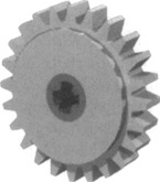
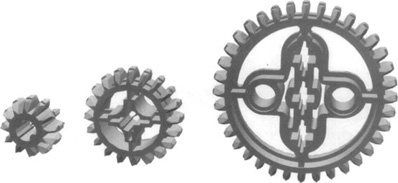
A single gear wheel alone is not very useful—in fact, it is not useful at all, unless you have in mind a different usage from that for which it was conceived! So, for a meaningful discussion, we need at least two gears. In Figure 2.1, you can see two very common LEGO gears: The right one is an 8t, and the left is a 24t. The most important property of a gear, as we’ll explain shortly, is its teeth. Gears are classified by the number of teeth they have; the description of which is then shortened to form their name. For instance, a gear with 24 teeth becomes “a 24t gear.”
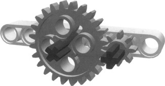
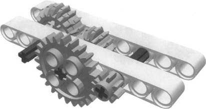
Let’s go back to our example. We have two gears, an 8t and a 24t, each mounted on an axle. The two axles fit inside holes in a beam at a distance of two holes (one empty hole in between). Now, hold the beam in one hand, and with the other hand gently turn one of the axles. The first thing you should notice is that when you turn one axle, the other turns too. The gears are transferring motion from one axle to the other. This is their fundamental property, their very nature. The second important thing you should notice is that you are not required to apply much strength to make them turn. Their teeth match well and there is only a small amount of friction. This is one of the great characteristics of the LEGO TECHNIC system: Parts are designed to match properly at standard distances. A third item of note is that the two axles turn in opposite directions: one clockwise and the other counterclockwise.
A fourth, and subtler, property you should have picked up on is that the two axles revolve at different speeds. When you turn the 8t, the 24t turns more slowly, whereas turning the 24t makes the 8t turn faster. Let’s explore this in more detail.
Let’s start turning the larger gear in our example. It has 24 teeth, each one meshing perfectly between two teeth of the 8t gear. While turning the 24t, every time a new tooth takes the place of the previous one in the contact area of the gears, the 8t gear turns exactly one tooth too. The key point here is that you need to advance only eight teeth of the 24 to make the small gear do a complete turn (360 degrees). After eight teeth more of your 24, the small gear has made a second revolution. With the last eight teeth of your 24, the 8t gear makes its third turn. This is why there is a difference in speed: For every turn of the 24t, the 8t makes three turns! We express this relationship with a ratio that contains the number of teeth in both gears: 24 to 8. We can simplify it, dividing the two terms by the smaller of the two (8), so we get 3 to l. This makes it very clear in numerical terms that one turn of the first corresponds to three turns of the second.
You have just found a way to get more speed! (To be technically precise, we should call it angular velocity, not speed, but you get the idea.) Before you start imagining mammoth gear ratios for race car robots, sorry to disappoint you—there is no free lunch in mechanics; you have to pay for this gained speed. You pay for it with a decrease in torque, or, to keep in simple terms, a decrease in strength.
So, our gearing is able to convert torque to velocity—the more velocity we want the more torque we must sacrifice. The ratio is exactly the same: If you get three times your original angular velocity, you reduce the resulting torque to one-third.
One of the nice properties of gears is that this conversion is symmetrical: You can convert torque into velocity or vice versa. And the math you need to manage and understand the process is as simple as doing one division. Along common conventions, we say that we gear up when our system increases velocity and reduces torque, and that we gear down when it reduces velocity and increases torque. We usually write the ratio 3:1 for the former and 1:3 for the latter.
When should you gear up or down? Experience will tell you. It largely depends on the motor you start with and the robot you want to end up with. The MINDSTORMS NXT servo motors are already geared down significantly within their plastic case, so they turn at a relatively slow velocity and produce quite a bit of torque (see Chapter 3). Without gearing up or down, they will provide a good match of speed and torque for many robots. If your vehicle will climb steep slopes or your robotic arm will lift some load, you may still want to gear down. If your vehicle will be lightweight and you want more speed, you can gear up.
Older LEGO motors have less internal gearing than MINDSTORMS NXT servo motors. They rotate at a higher velocity but produce less torque. When using them, you will generally want to gear down to reduce speed and increase torque.
One last thing before you move on to the next topic. We said that there is no free lunch when it comes to mechanics. This is true for this conversion service as well: We have to pay something to get the conversion done. The price is paid in friction—something you should try to keep as low as possible—but it’s unavoidable. Friction will always eat up some of your torque in the conversion process.
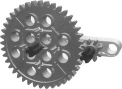
The largest LEGO gear is the 40t, and the smallest is the 8t (used in the previous discussion). Thus, the highest ratio we can obtain is 8:40, or 1:5 (Figure 2.2).
What if you need an even higher ratio? In such cases, you should use a multistage reduction (or multiplication) system, usually called a geartrain. Look at Figure 2.3. In this system, the result of a first 1:3 reduction stage is transferred to a second 1:3 reduction stage. So, the resulting velocity is one-third of one-third, which is one-ninth, and the resulting torque is three times three, or nine. Therefore, the ratio is 1:9.
Geartrains give you incredible power, because you can trade as much velocity as you want for the same amount of torque. Two 1:5 stages result in a ratio of 1:25, whereas three of them result in a 1:125 system! All this strength must be used with care, however, because your LEGO parts may get damaged if for any reason your robot is unable to convert it into some kind of work. In other words, if something gets jammed, the strength of a LEGO motor multiplied by 125 is enough to deform your beams, wring your axles, or break the teeth of your gears. We’ll return to this topic later.
In your NXT box, you’ve probably found another strange gear, a black one that resembles a sort of cylinder with a spiral wound around it. Is this thing really a gear? Yes, it is, but it is so peculiar we have to give it special mention.
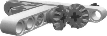
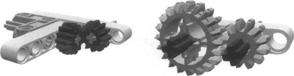
In Figure 2.4, you can see a worm gear engaged with more familiar gears. The assembly on the right uses a special LEGO part. It is called a worm gear block. With this single piece you can connect the worm gear to a 24t gear. In just building these simple assemblies, you will discover many properties. Try to turn the axles by hand. Notice that although you can easily turn the axle connected to the worm gear, you can’t turn the one attached to the other gears. We have discovered the first important property: The worm gear leads to an asymmetrical system; that is, you can use it to turn other gears, but it can’t be turned by other gears. The reason for this asymmetry is, once again, friction. Is this a bad thing? Not necessarily. It can be used for other purposes.
Another fact you have likely observed is that the two axles are perpendicular to each other. This change of orientation is unavoidable when using worm gears. You may also have noticed when building these assemblies that the worm gear slides easily along an axle. Sometimes this is useful, but most of the time you will have to fix it in place along the axle with bushings.
Turning to gear ratios, you’re now an expert at doing the math, but you’re probably wondering how to determine how many teeth this worm gear has! To figure this out, instead of discussing the theory behind it, we proceed with our experiment. Taking the middle assembly used in Figure 2.4, we turn the worm gear axle slowly by exactly one turn, at the same time watching the 24t gear. For every turn you make, the 24t rotates by exactly one tooth. This is the answer you were looking for: The worm gear is a It gear! So, in this assembly, we get a 1:24 ratio with a single stage. In fact, we could go up to 1:40 using a 40t instead of a 24t.
The asymmetry we talked about before makes the worm gear applicable only in reducing speed and increasing torque, because, as we explained, the friction of this particular device is too high to get it rotated by another gear. The same high friction also makes this solution very inefficient, as a lot of torque gets wasted in the process.
As we mentioned earlier, this outcome is not always a bad thing. There are common situations where this asymmetry is exactly what we want. One example would be when designing a robotic arm to lift a small load. Suppose we use a 1:25 ratio made with standard gears: What happens when we stop the motor with the arm loaded? The symmetry of the system transforms the weight of the load (potential energy) into torque, and the torque into velocity, and the motor spins back, making the arm go down. In this case, and in many others, the worm gear is the proper solution, its friction making it impossible for the arm to turn the motor back.
We can summarize all this by saying that in situations when you desire precise and stable positioning under load, the worm gear is the right choice. It’s also the right choice when you need a high reduction ratio in a small space, because it allows very compact assembly solutions.
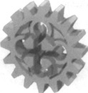
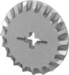
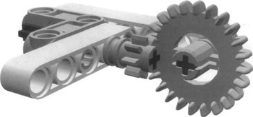
Another special device you should get familiar with is the thick 24t white gear, which has strange markings on its face (Figure 2.5). It is a clutch gear, and in the next part of this section we’ll discover just what it does.
Our experiment this time requires very little work; just put one end of an axle inside the clutch gear and the other end into a standard 24t to use as a knob. Keep the latter in place with one hand and slowly turn the clutch gear with the other hand. It offers some resistance, but it turns. This is its purpose in life: to offer some resistance, then give in!
This clutch gear is an invaluable help to limit the strength you can get from a geared system, and this helps to preserve your motors and your parts, and to resolve some difficult situations. The mysterious “2.5*5 Ncm” writing stamped on it (as explained earlier, Ncm is a newton-centimeter, the unit of measurement for torque) indicates that this gear can transmit a maximum torque of about 2.5 to 5 Ncm. When exceeding this limit its internal clutch mechanism starts to slip.
What’s this feature useful for? You have seen before that through some reduction stages you can multiply your torque by high factors, thus getting a system strong enough to actually damage itself if something goes wrong. This clutch gear helps you avoid this, limiting the final strength to a reasonable value.
There are other cases in which you don’t gear down very much and the torque is not enough to ruin your LEGO parts, but if the mechanics jam, the motor stalls—this could be a very bad thing, because your motor draws a lot of current when stalled. The clutch gear prevents this, automatically disengaging the motor when the torque becomes too high.
In some situations, the clutch gear can even reduce the number of sensors needed in your robot. Suppose you build a motorized mechanism with a bounded range of action, meaning that you simply want your subsystem (arms, levers, actuators—anything) to be in one of two possible states: open or closed, right or left, engaged or disengaged, with no intermediate position. You need to turn on the motor for a short time to switch the mechanism from one state to the other, but unfortunately it’s not easy to calculate the precise time a motor needs to be on to perform a specific action (even worse, when the load changes, the required time changes too). If the time is too short, the system will result in an intermediate state, and if it’s too long, you might do damage to your motor.
You can use a sensor to detect when the desired state has been reached. If you are using NXT servo motors, you could simply use the built-in motor encoders to determine when you should start and stop the motor (we will discuss this more in Chapter 4). However, you might choose to use a different LEGO motor to power your subsystem. In this case, you will not have a rotation sensor built-in to check. Without a secondary sensor, you will have to run a motor for a specific time. If you put a clutch gear somewhere in the geartrain, you can now run the motor for the approximate time needed to reach the limit in the worst load situation, because the clutch gear slips and prevents any harm to your robot and to your motor if the latter stays on for a time longer than required.
There’s one last topic about the clutch gear we have to discuss: where to put it in our geartrain. You know that it is a 24t and can transmit a maximum torque of 5 Ncm, so you can apply here the same gear math you have learned so far. If you place it before a 40t gear, the ratio will be 24:40, which is about 1:1.67. The maximum torque driven to the axle of the 40t will be 1.67 multiplied by 5 Ncm, resulting in 8.35 Ncm. In a more complex geartrain such as that in Figure 2.6, the ratio is 3:5 and then 1:3, coming to a final 1:5; thus, the maximum resulting torque is 25 Ncm. A system with an output torque of 25 Ncm will be able to produce a force five times stronger than one of 5 Ncm. In other words, it will be able to lift a weight five times heavier.
The clutch gear isn’t the only way to introduce slip into a system. Later in this chapter we’ll discuss pulleys and belts, another way to introduce slip into a system.
From these examples, you can deduce that the maximum torque produced by a system that incorporates a clutch gear results from the maximum torque of the clutch gear multiplied by the ratio of the following stages. When you are gearing down, the more output torque you want, the closer you have to place your clutch gear to the source of power (the motor) in your geartrain. On the contrary, when you are reducing velocity, not to get torque but to get more accuracy in positioning, and you really want a soft touch, place the clutch gear as the very last component in your geartrain. This will minimize the final supplied torque.
This might sound a bit complex, but we again suggest you learn by doing, rather than by simply reading. Prototyping is a very good practice. Set up some very simple assemblies to experiment with the clutch gear in different positions, and discover what happens in each case.
The LEGO gear set includes many different types of gear wheels. Up to now, we played with the straight 8t, 24t, and 40t, but the time has come to explore other kinds of gears, and to discuss their use according to size and shape.
In studless buildings, unlike traditional studded building, the holes in TECHNIC beams stacked atop one another are the same distance apart as holes in a single beam. This means gears connected together will be the same number of holes apart, whether connected horizontally along the same beam or vertically across multiple beams (see Figure 2.7 and Figure 2.8).
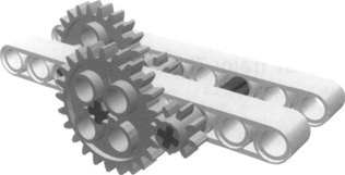
Another common straight gear is the 16t gear (Figure 2.9).
Its radius is 1, and it combines well with a copy of itself at a distance of two. Getting it to cooperate with other straight gears, however, is very difficult.
When you are using a pair of 16t gears, the resulting ratio is 1:1. You don’t get any effect on the angular velocity or torque (except in converting a fraction of them into friction), but indeed there are reasons to use them as a pair—for instance, when you want to transfer motion from one axle to another with no other effects. This is, in fact, another task that gears are commonly useful for. There’s even a class of gears specifically designed to transfer motion from one axle to another axle perpendicular to it, called bevel gears.
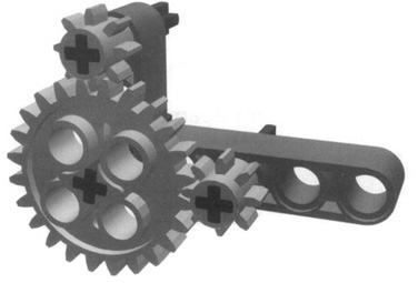
The most common member of this class is the 12t bevel gear, which can be used only for this task (Figure 2.10), meaning it does not combine at all with any other LEGO gear we have examined so far. Nevertheless, it performs a very useful function, allowing you to transmit the motion toward a new direction, while using a minimum of space. There’s also a 20t bevel conical gear with the same design of the common 12t (Figure 2.11). Both of these bevel gears are half a beam in thickness, whereas the other gears are one beam in thick.
The 24t gear also exists in the form of a crown gear, a special gear with front teeth that can be used like an ordinary 24t, but can also combine with another straight gear to transmit motion in an orthogonal direction (that is, composed of right angles), possibly achieving at the same time a ratio different from 1:1 (Figure 2.12).
You may have noticed another group of gears in your collection. They are wider and the edges of their teeth look like the bevel gear on both sides. These are double bevel gears. Count the number of teeth on them. You will find they are 12t, 20t, and 36t gears (see Figure 2.13).
You will notice when you place these gears on a single beam that two gears of the same size will not mesh with one another. For this reason, double bevel gears are generally used in pairs of different sizes, either a 12t and a 20t, or a 12t and a 36t. These gears are designed to work well in both perpendicular and horizontal setups (Figure 2.14).
Mismatched pairs of double bevel gears use the same hole spacing as straight gears, so pairs of them can be used in place of a pair of straight gears, offering some new gear ratios—for example, a 12t and a 20t double bevel gear pair mesh at a distance of 2, the same as an 8t and 24t straight gear pair. Be careful when mixing and matching double bevel gears and straight gears; although they use some of the same hole spacing, double bevel gears and straight gears don’t work with each other. To use them together you will have to use them in pairs (Figure 2.15).
The last gear that we’ll describe doesn’t look like a gear at all. In fact, it isn’t known as a gear, but as a knob wheel (Figure 2.16)
Examine the knob wheel and you will find that it is basically a 4t gear (see Figure 2.17). Connect it with another copy of itself and you will see that it works very well as a gear. Like double bevel gears, it can also work in perpendicular setups.
In perpendicular setups, knob wheels have one major advantage over double bevel gears. Connect two knob wheels. Examine how much area on each tooth of the knob wheel contacts a tooth on the other. Compare that to a pair of double bevel gears. The knob wheels have much more contact area. This means they can transmit much more torque from one axle to the other.
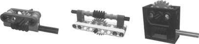
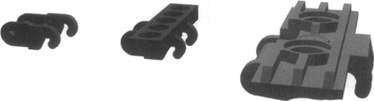
The final class of gears is actually a combination of gears and bricks. They are clear LEGO bricks with gears encased inside them and axle holes on the faces. These bricks are commonly referred to as TECHNIC gearboxes (see Figure 2.18). They come in three different types. The first is a worm gearbox that functions exactly like the worm gear block with the 24t gear discussed earlier. In fact, it even has the same gear ratio, as the gear inside is a 24t gear. The second type is a 90-degree angle gearbox. Encased within it are two bevel gears at a right angle to each other. This can be used exactly like the bevel gears previously discussed. The final gearbox type also uses bevel gears at right angles. However, instead of having just two axle holes, it has three, so it can be used as a T-connection. It can be used to split the output of a single driven axle into two outputs.
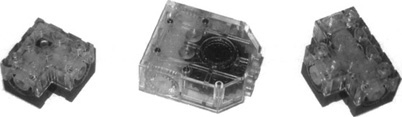
These gearboxes are functionally no different from the bevel gears previously discussed. The same gear trains could be built with the bevel gears and worm gears already discussed. However, the gearboxes do have two major advantages. They take up very little space and are able to transmit quite a bit of torque. The gears are firmly encased in the LEGO bricks, so there is very little opportunity for the gears to slip. These gearboxes do have two drawbacks. The first is their availability. The gearboxes have been included in only a few sets and are not widely available. Second, the bricks are studded, which means they are primarily designed to be used with traditional studded TECHNIC bricks, not the studless beams included in the NXT kit and most new TECHNIC sets. This doesn’t mean they cannot be used in studless constructions; as you will see in Chapter 6, using both studded and studless building techniques in a single creation is possible.
Pulleys and belts are two classes of components designed to work together and perform functions similar to that of gears—similar, that is, but not identical. They have indeed some peculiarities which we shall explore in the following paragraphs. The MINDSTORMS NXT kit includes a few pulleys, but no belts. You will have to buy them separately.
Chains are also not part of the basic NXT kit. Though not essential, they allow you to create mechanical connections that share some properties with both geartrains and pulley-belt systems.
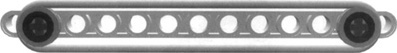
Pulleys are like wheels with a groove (called a race) along their diameter. The LEGO TECHNIC system currently includes four kinds of pulleys, shown in Figure 2.19.
The smallest one (a) is actually the half-size bush, normally used to hold axles in place to prevent them from sliding back and forth. Because it does have a race, it can be properly termed a pulley. Its diameter is one LEGO unit, with a thickness of half a unit.
The small pulley (b) is 1 unit in thickness and about 1.5 units in width. It is asymmetrical, however, because the race is not in the exact center. One side of the axle hole fits a rubber ring that’s designed to attach this pulley to the micromotor. The medium pulley (c) is again half a unit thick and 3 units in diameter. Finally, the large pulley (d) is 1 unit thick and about 4.5 units in diameter.
LEGO belts are rings of rubbery material that look similar to rubber bands. They come in four versions, with different colors corresponding to different lengths: white, blue, red, and yellow. Don’t confuse them with actual rubber bands: Rubber bands have much greater elasticity, and for this reason are much less suitable to the transfer of motion between two pulleys. This is, in fact, the purpose of belts: to connect a pair of pulleys. LEGO belts are designed to perfectly match the race of LEGO pulleys.
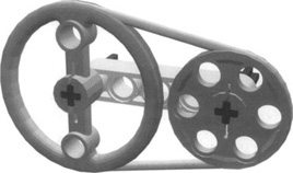
Let’s examine a system made of a pair of pulleys connected through a belt (Figure 2.20). The belt transfers motion from one pulley to the other, making them similar to a pair of gears. How do you compute the ratio of the system? You don’t have any teeth to count... The rule with pulleys is that the reduction ratio is determined by finding the ratio between their diameters (this rules applies to gears too, but the fact that their circumference is covered with evenly spaced teeth provides a convenient way to avoid measurement). You actually should consider the diameter of the pulley inside its race, because the sides of the race are designed specifically to prevent the belt from slipping from the pulley and don’t count as part of the diameter over which the belt acts.
You must also consider that pulleys are not very suitable to transmitting high torque, because the belts tend to slip. The amount of slippage is not easy to estimate, as it depends on many factors, including the torque and speed, the tension of the belt, the friction between the belt and the pulley, and the elasticity of the belt.
For those reasons, we preferred an experimental approach and measured some actual ratios among the different combinations of pulleys under controlled conditions. You can find our results in Table 2.1.
These values may change significantly in a real-world application, when the system is under load. Because of this, it’s best to think of the figures as simply an indication of a possible ratio for systems where very low torque is applied. Generally speaking, you should use pulleys in your first stages of a reduction system, where the velocity is high and the torque is still low. You could even view the slippage problem as a positive feature in many cases, acting as a torque-limiting mechanism such as the one we discussed in the clutch gear, with the same benefits and applications. However, be careful when using belts and pulleys to allow slip in a system. Belts turning around pulleys that are not turning will cause friction and heat to build up. In time, the belt will break. Also, the belts have a tendency to jump off the pulley, causing your entire system to fail.
Another advantage of pulleys over gear wheels is that their distance is not as critical. Indeed, they help a great deal when you need to transfer motion to a distant axle (Figure 2.21). And at high speeds, they are much less noisy than gears—a facet that occasionally comes in handy.
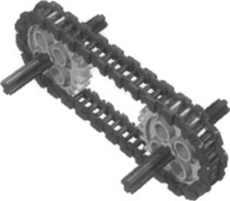
LEGO chains come in two flavors: chain links and tread links. LEGO produces two different types of tread links. The first shares the same hooking system with the chain links. They are freely mixable to create a chain of the required length. The second tread link is a newer introduction and uses a different hooking system, so it can be connected only with other copies of itself (see Figure 2.22).
Chains are used to connect gear wheels in the same way belts connect with pulleys (see Figure 2.23). They share similar properties as well: Both systems couple parallel axles without reversing the rotation direction and both give you the chance to connect distant axles. The big difference between the two is that chain links don’t allow any slippage, so they transfer all the torque (actually, the maximum torque a chain can transfer depends on the resistance of its individual links, which in the case of LEGO chains is not very high). On the other hand, they introduce further friction into the system, and for this reason are much less efficient than direct gear matches. You will find chains useful when you have to transfer motion to a distant axle in low-velocity situations. The ratio of two gears connected by a chain is the same as their corresponding direct connection. For example, a 16t connected to a 40t results in a 2:5 ratio.
TECHNIC tread links can be used to make tracked robots (see Figure 2.24). However, like most LEGO parts, they are plastic. They provide very little grip when on slippery surfaces such as wood, tile, or plastic. They work better on other surfaces such as carpet.
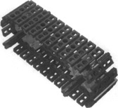
The gears used to drive chains or treads are commonly referred to as sprockets. LEGO chains and the older tread links use straight gears for their drive sprockets. The new-style tread link uses a new LEGO drive sprocket design that meshes only with the new tread link. It will not mesh with any other gear types.
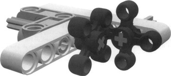
We want to introduce you to a very special device now: the differential gear.. You probably know that there’s at least one differential gear in every car. What you might not know is why the differential gear is so important.
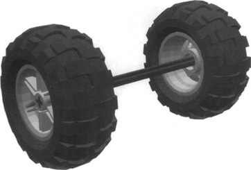
Let’s do an experiment together. Take two wheels from your NXT kit and connect their hubs with the longest axle (Figure 2.25). Now put the wheels on your table and push them gently: They run smoothly and advance some feet, going straight. Very straight. Keep the axle in the middle with your fingers and try to make the wheels change direction while pushing them. It’s not so easy, is it?
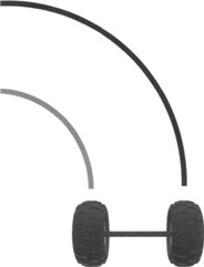
The reason is that when two parallel wheels turn, their paths must have different lengths, the outer one having a longer distance to cover (Figure 2.26). In our example, in which the wheels are rigidly connected, at any turn they cover the same distance, so there’s no way to make them turn unless you let one slip a bit.
The next phase of our experiment requires that you now build the assembly shown in Figure 2.27. You see a differential gear with its three 12t bevel gears, two 6-length axles, and four beams connected together to provide you with a way to handle this small system. Placing the wheels again on your table, you will notice that while pushing them, you can now easily turn smoothly in any direction. Please observe carefully the body of the differential gear and the central bevel gear: When the wheels go straight, the body itself rotates while the bevel gear is stationary. On the other hand, if you turn your system in place, the body stays put and the bevel gear rotates. In any other intermediate case, both of them rotate at some speed, adapting the system to the situation. Differentials offer a way to put power to the wheels without the restriction of a single fixed drive axle.
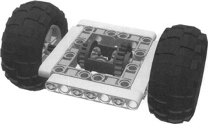
To use this configuration in a vehicle, you simply have to apply power to the body of the differential gear, which incorporates a 24t on one side and a 16t on the other.
The differential gear has many other important applications. You can think of it as a mechanical adding/subtracting device. Again place the assembly from Figure 2.27 on your table. Rotate one wheel while keeping the other from turning; the body of the differential gear rotates half the angular velocity of the rotating wheel. You already discovered that when turning our system in place, the differential does not rotate at all, and then when both wheels rotate together, the differential rotates at the same speed as well. From this behavior, we can infer a simple formula:
(Iav1 + Iav2) / 2 = Oav
where Oav is the output angular velocity (the body of the differential gear), and Iavl and lav2 are the input angular velocities (the two wheels). When applying this equation, you must remember to use signed numbers for the input, meaning that if one of the input axles rotates in the opposite direction of the other, you must input its velocity as a negative number. For example, if the right axle rotates at 100 revolutions per minute (rpm) and the left one at 50 rpm, the angular velocity of the body of the differential results in this:
(100 rpm + 50 rpm ) / 2 = 75 rpm
There are situations when you deliberately reverse the direction of one input, using idler gears, to make the differential sensitive to a difference in the speed of the wheels, rather than to their sum. Reversing the input means that you must make one of the inputs negative. See what happens to the differential when both wheels run at the same speed—let’s say, 100 rpm:
(100 rpm - 100 rpm ) / 2 = 0 rpm
It doesn’t move! As soon as a difference in speed appears, the differential starts rotating with an angular velocity equal to half this difference:
(100 rpm - 98 rpm ) / 2 = 1 rpm
This is a useful trick when you want to be sure your wheels run at the same speed and cover the same distance: Monitor the body of the differential and slow the left or right wheel appropriately to keep it stationary. See Chapter 8 for a practical application of this trick.
Few pieces of machinery can exist without gears, including robots, and you ought to know how to get the most benefit from them. In this chapter, you were introduced to some very important concepts: gear ratios, angular velocity, force, torque, and friction. Torque is what makes your robot able to perform tasks involving force or weight, such as lifting weights, grabbing objects, or climbing slopes. You discovered that you can trade off some velocity for some torque, and that this happens along rules similar to those that apply to levers: The larger the distance from the fulcrum, the greater the resulting force.
The output torque of a system, when not properly directed to the exertion of work, or when something goes wrong in the mechanism itself, can cause damage to your LEGO parts. You learned that the clutch gear and belts and pulleys are precious tools to limit and control the maximum torque so as to prevent any possible harm.
In addition to straight gears, you were also introduced to bevel and double bevel gears. Bevel gears are useful to transfer motion between perpendicular axles. Double bevel gears can transfer motion between both perpendicular and parallel axles, as can the knob wheel.
Gears are not the only way to transfer power; we showed that pulley-belt systems, as well as chains, may serve the same purpose and help you in connecting distant systems. Belts provide an intrinsic torque-limiting function and do well in high-speed, low-torque situations. Chains, on the other hand, don’t limit torque but do increase friction, so they are more suitable for transferring power at slow speeds.
Last but not least, you explored the surprising properties of the differential gear, an amazing device that can connect two wheels so that they rotate when its body rotates, still allowing them to turn independently. The differential gear has some other applications too, because it works like an adder-subtracter that can return the algebraic sum of its inputs.
If these topics were new to you, we strongly suggest you experiment with them before designing your first robot from scratch. Take a bunch of gears and axles and play with them until you feel at ease with the main connection schemes and their properties. This will offer you the opportunity to apply some of the concepts you learned from Chapter 1 about bracing layers with vertical beams to make them more solid (when you increase torque, many designs fall apart unless properly reinforced). You won’t regret the time spent learning and building on this knowledge. It will pay off, with interest, when you later face more complex projects.