
Solutions in this chapter:
It’s always great fun and very satisfying to see your robot pick things up from the ground, or take an object when you offer it. In this chapter, we’ll illustrate some ways to build arms, hands, clamps, pliers, and other tools to grab and handle objects. One of the basic measurements of movement we’ll explore is the degree of freedom (DOF), or the number of directions in which an object (such as a robotic arm) has a range of motion. In the last part of the chapter, we’ll show you methods by which your robot can find the objects, the most challenging part of the job, and distinguish among target objects (those you wish to pick) and walls or other obstacles.
We divide the process of grabbing an object into four steps:
Find an object.
Distinguish target objects from walls, other obstacles, or “dummy” objects.
Position the grabber and/or object in correct orientation.
Operate the grabber to catch the object.
The order of these steps may vary, as sometimes your robot must capture the object before it can distinguish between a “target” object and “dummy” objects (for example, by a color sensor mounted on top of the grabber). We’ll start from the last step which is more technical, and then discuss the other steps which rely mainly on programming.
In Chapter 10, we illustrated that pneumatic cylinders are generally the ideal choice for making grabbing devices, or grabbers. We will explain the advantage of pneumatic grabbers in more detail in the next section. Unfortunately, pneumatics is not always a possible option. You might not have LEGO pneumatic parts or you don’t have room on your robot to fit a pneumatic compressor (a pressure switch and some motor-driven valve switches). We’ve seen that NXT-to-pneumatics interfaces are rather cumbersome. We will defer the discussion of pneumatic grabbers until after we explain how to use the NXT servo motors to drive your grabber.
The problem with using motors is not in opening or closing the hand; it’s in getting the hand to apply continuous pressure on the object to prevent it from falling. This means you cannot just position the fingers around it. You must also exert a force that tightens around the object even though you are not moving the fingers anymore. If you are familiar with (or still use with your NXT) the old electric motors of the RCX, you probably know that stalling them (having them powered but their movements blocked) could cause their internal gears to wear and the motor to overheat. We have explained in Chapters 2 and 3 that the new NXT servo motors are more robust and can withstand short-term stalling. They are, however, extremely power-hungry and would waste a lot of your batteries’ power doing so. Long-term stall may still heat up the servo motors, and although they have a protection mechanism which will shut them down before they are damaged (dropping your object...), overheating is still undesirable. When you know you’re going to handle a soft object that has some intrinsic elasticity, you can sometimes simply brake the motor, which can, combined with friction among gears, keep the fingers against the object. Try this with TriBot and a sponge ball! If you have heavier objects, however, you will need to find ways to reduce the power forcing the fingers to open. Again, using the TriBot example, try catching the NXT plastic ball. You will not be able to do this without constantly powering the motor, forcing it to close the claws on the ball. A simple way to overcome this problem is to use a worm gear. The simple grabber in Figure 11.1 uses a worm gear that drives the fingers. The worm gear prevents them from releasing the ball when the motor is not powered (either in “brake” or in “coast” mode). Recall from Chapter 2 that the worm gear is a one-way gear: It can turn a meshing gear but cannot be turned by it.
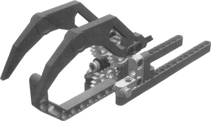
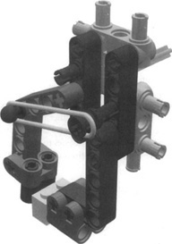
Figure 11.2 shows a different design, where the rotary motion from the motor gets converted into linear motion through a worm gear and two translating axles. It’s this motion that operates the movable fingers of the grabber. The translation of rotary motion to linear motion is performed by the two half-bushings with mesh the teeth of the worm gear; when the worm gear rotates, the bushings get pushed or pulled, and the axles where they are mounted move accordingly.
The same principle is used also in the grabber shown in Figure 11.3. Here only the two cone-toed fingers move, with a very compact worm gear pushing them to close on the third finger.
We’ve repeatedly said that pneumatic cylinders are your best choice in this field, but let’s analyze what makes them so good to see whether we can learn something and replicate the same behavior. A pneumatic cylinder can be considered a two-state system: The cylinder is either extended or retracted (we are deliberately ignoring that you can somehow manually stop the cylinder in an intermediate position, centering the switch, and assuming that the switch is in one of its extreme positions). If something prevents the cylinder from actually reaching one of these states, it can, however, continue to push in that direction. Its natural behavior is to move until it finds resistance that balances its inner pressure. This pressure is what keeps the fingers applying a force to the object, thus making your robotic hand hold it firmly.
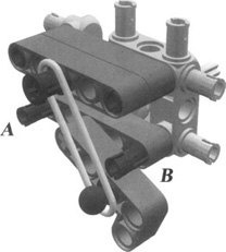
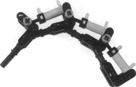
The point now is to replicate this behavior in a nonpneumatic device. Is it possible? Yes. Figure 11.4 shows an example of a simple bistable system, so-called because it has two default states, or two possible rest positions to which it tends to go. A rubber band forces the liftarm to stay against one of the two black pegs, either in A or in B. If you move the liftarm slightly from the peg and then release it, it goes back against the peg. If you move it a bit more and pass the midpoint between A and B, it goes to the other peg. You need to provide only enough force to make the system switch from one to the other; the rubber band will do the rest.
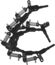
Applying this principle, you can design the pliers shown in Figure 11.5, which are suitable for grabbing very small objects such as a 1 × 2 brick (seen at the bottom of the figure). To actually use them in a robot you must add a motor that, through brief impulses, rotates the axle connected to the liftarm, shifting the pliers into their open or closed state.
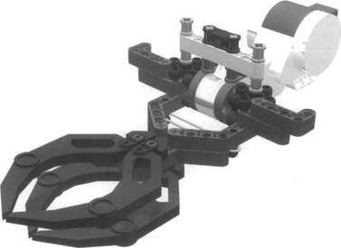
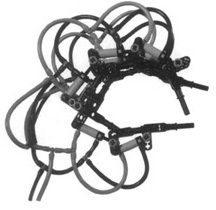
The same approach can be used for larger hands. In Figure 11.6, we demonstrate how one can make a TriBot-like grabber which uses a bi-stable mechanism. Here the rubber band between the two hands keeps them forcing on the object in the closed state, while you can still open the hand with the motor (low power with speed regulation works best for this design), and the rubber band keeps it open afterward.
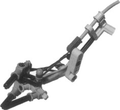
What if you need a compact, lightweight grabber? The flex system we briefly described in Chapter 9 allows you to transfer motion to distant parts, away from the motors and gears. Figure 11.7 shows a small operating hand based on this technique. A pair of opposing rubber bands introduces a degree of elasticity into the system, and helps the fingers return to their default setting once the hand comes to rest in its open position.
Tip
Try to use short fingers whenever possible. An object held by long fingers exerts more torque on the gears, just as a long lever makes lifting a heavy weight easier.
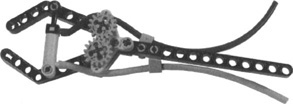
In discussing the advantages of pneumatics when grabbing objects, we must also mention that tubing provides a simple way to keep bulky things far from the movable parts. Compare the simplicity of the pliers in Figure 11.8 with the complex gearings of the previous examples. The difference is dramatic.
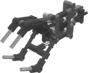
Pneumatics makes it possible to build more versatile hands than gear-driven grabbers. Figure 11.9 shows a three-joint pneumatic finger. This is a nice design, but it’s a pity that it requires all three ports of your NXT to be fully controlled. How could you control more than a finger if you are already out of ports? To make the system simpler, though still useful, you can connect all the cylinders together (you won’t be able to move a single segment of the finger by itself, but the finger can still adapt well to the shape of many different objects). This is the technique we used in the three-finger pneumatic hand shown in Figures 11.10 and 11.11, which is controlled by a single valve switch.
Bricks & Chips...
Understanding Degrees of Freedom
If you look carefully at your hands, you’ll discover that they are an incredible piece of machinery, capable of handling a wide array of objects of every size and shape. Just think about the long list of verbs describing all the things hands can do: grab, handle, hold, take, squeeze, grip, point, pinch, shake, roll, press, grasp, push, pull ... and those are only a few of the terms. Where does all this versatility come from?
Observe your finger while you move it. You’ll notice four individual movements: three for the joints—from the fingertip to the hand—that let you bend the finger, and a fourth that allows for slight left-right motion where the finger joins the hand. Although you usually operate more than one muscle at the same time, you can also move them individually (say, with your other hand). Multiply these four movements by five (for a hand’s five fingers) and add the mobility given by the wrist, and 25 movements or so come to mind, which, in turn, lead to a huge number of combinations and configurations. This is what makes your hand able to conform to the shape of the object you want to handle. To complete the picture, consider that you can control the strength of each muscle so finely that you can pick up a delicate wine glass without damaging it, yet so firmly grip a baseball bat that you can send a ball over the right-field wall.
Every independent movement represents a degree of freedom (DOF), something that can happen without affecting and being affected by other movements in the same device. Most of the previous examples were very simple mechanisms with just one degree of freedom, being that all the possible positions of the “fingers” were determined by a single motor or pneumatic cylinder. The DOF concept helps you understand in terms of numbers why those simple hands diverged so widely from the flexibility a human hand has.
The DOF concept will help us understand the advantage of the pneumatic hand we showed in Figure 11.11. When we couple the movement of several “fingers” by a geartrain {such as the simple hand in Figure 11.1), all fingers move by a fixed amount (linear or angular) for each revolution of the motor, as determined by the gear ratios. If one of the fingers gets stuck, all other fingers get stuck too. On the other hand, when we increase the internal pressure in the cylinders of Figure 11.11, the individual cylinders extend and close the fingers. Here, if one finger gets stuck, the others will still extend until they balance the internal pressure. Thus, even though it seems that all cylinders move concurrently in the absence of a load, they are in fact mutually independent and the number of DOFs equals the number of cylinders.
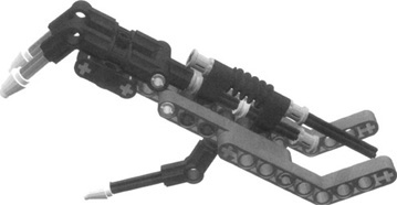
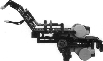
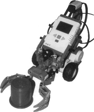
The DOF concept applies not only to hands, but also to any mechanical device. The RoboArm T-56 in the Robo Center has three DOFs—one motor rotates the turntable, another motor extends the arm, and a third motor opens and closes the grabber. Figure 11.12 shows another type of robotic arm. Here one motor moves the grabber forward and backward using a long worm gear, and the other motor opens and closes the grabber (the same grabber as in Figure 11.3). This arm has two degrees of freedom.
Obviously, you cannot aim to make a robotic hand with 25 degrees of freedom using your MINDSTORMS NXT kit. Each degree of freedom will typically require a dedicated motor or pneumatic cylinder, and this puts the task out of reach. You should stay with something much simpler and consequently reduce the range of objects your mechanical hand will be able to grab. This is sometimes limiting, but in many situations you will know in advance the types and shapes of objects your robot will be expected to handle, making your task less demanding. In contests that involve collecting things, for example, your robot usually will deal with very specific objects, such as soda cans, small LEGO cubes, or marbles, and because of this you can design it to target those types of objects.
Generally speaking, locating a point in a plane requires two DOFs, whereas locating a point in space requires three. There are many examples of two-DOF and three-DOF mechanisms in everyday objects: An ink-jet printer has two DOFs, one corresponding to the head movement and the other to the paper feeding. A construction crane is an example of a machine with three DOFs: The hook can go up and down, it’s attached to a carriage that moves back and forth along the boom, and finally, the boom can rotate. With the three output ports of your NXT, you can drive a robotic arm that addresses any point inside a delimited space, called the operating envelope, exactly like the crane of the preceding example. If you also want to pick up and drop objects, you would need another port.
Building robotic arms and hands is the easy part of the job. The hardest part is finding the objects to grab. We will skip the case where your robot knows the position of the objects, because this brings into play a general navigation problem we’ll discuss in Chapter 13. So, for the time being, we’ll stick with the fact that the robot knows nothing about the location of the objects.
As we explained when talking about bumpers in Chapter 4, navigation in real environments is quite a tough task, and distinguishing a specific object from others makes things much harder. So the second assumption we make here is that you know what kind of object you’re expected to handle, as well as all the details of the environment where your robot moves (typically an artificial one prepared for the task). You might think that we are introducing too many simplifications here, but even in these conditions, the task remains quite hard. It’s very important that you progress in short steps. The most common mistake of beginning builders is to start out with goals too difficult for their robots, where mechanical and programming difficulties add to navigation problems. As a general approach, we suggest you apply the “divide and conquer” strategy and solve the problems one by one.
Let’s make an example: a simple variation on line following that might involve removing objects placed along the path. A very simple bumper is probably enough to detect objects. The arm will be more or less sophisticated depending on whether you have to collect them or just move them out of the way.
In wider environments, things become trickier. Imagine you have to find things in a delimited space with no walls (how could a space be delimited without having walls? By using different colors on the floor and reading them with a light sensor facing down!). You can still use a bumper, and make your robot move around at random or follow some kind of scheme. Depending on whether you are participating in a contest with specific rules, you could make this approach more efficient using a sort of funnel to convey the objects against the bumper, or some long antennas (connected to a touch sensor) to help you detect objects in a wider area.
If the objects in your environment are large enough, you can use the ultrasonic (US) sensor to find them. Figure 11.13 shows a modified TriBot that uses ultrasound to find soda cans and plastic cups. There are several important issues to remember when using ultrasound:
It works well for relatively large, solid objects with more or less flat surfaces. This is due to the nature of ultrasonic sound waves—they do not reflect back (or are attenuated drastically) from round or spongy surfaces. An alternative can be the Mindsensors IR distance sensor, which is relatively unaffected by the object’s composition and shape.
Putting the US sensor too high can cause your robot to lose track of the object when it gets closer. Putting it too low can lead the sensor to receive echoes from ground reflections, thereby confusing the measurement.
The ultrasound beam is about 30 degrees wide. This means that even a “point” object such as a standing marker would seems to occupy 30 degrees around your NXT. This also means that your robot may be facing an object farther away, but because there is a closer object a little to its left (or right), it will see this one instead.
Approaching a flat surface in an oblique angle may result in a weird US readout, basically due to weak reflection back toward the sensor (most of the sound is reflected away from the sensor, just like the reflection of a flashlight from a mirror).
Using more than one US sensor in a room (say, in a competition) may be problematic, as the sensor cannot distinguish between its own generated waves and other sensors’ ultrasound waves. It is possible to synchronize US sensors (as we discuss later on), but this requires cooperation with your opponents...
How can you cover the whole space while searching with a US sensor? One way is to perform a 360-degree scan (typically by rotating the whole robot), looking for anything within, say, 30 inches. If you find something, go toward it one-half its distance; if not, pick a random direction and move 15 inches (half the target threshold distance). Repeating this basic step will give you good coverage of the area around you. Of course, you can improve on this simple scheme by remembering your previous “step,” and so on.
You can use other sensors to help you find your target. For example, if your target emits light (which is strong enough to be detected from a distance, or alternatively you dim the lights in the room) or makes a sound, you can use the light or sound sensor to locate the target. A good practice in such cases is to have your robot move some distance, stop, rotate 360 degrees while measuring the light/sound level and keeping a record of the motor encoder value of the largest level, and then rotate to the orientation of maximal intensity and move some fixed distance again. Repeating this procedure again and again will finally lead you close to your target. If the target blinks or makes a nonconstant sound (like another NXT playing music), you can use two identical sensors separated a few inches apart and use the difference between them to decide whether the target is to the left or to the right, similar to how your own ears identify the direction of noises. Another, more specific, example is the IRSeeker sensor from HiTechnic, aimed at locating the IR-emitting Junior Cup ball. This sensor gives a 1-9 value telling the NXT in which sector (out of 240 degrees) the ball is, and another 1-9 value giving the signal strength (corresponding to the distance to the ball).
If you did the NXT-G Robo Center TriBot missions, you might have noticed that placing the ball not directly in front of the TriBot will sometimes cause the grabber to fail to catch it. This demonstrates another important issue in grabbing objects: aligning the grabber and the object so that the object can be caught by it (i.e., the object must be within the operating envelope of the grabber, as we discussed earlier).
The easiest way, of course, is to force the object to reach the grabber. You can do this, for instance, by having a “funnel”-like construction in front of your robot so that the object is pushed to a defined position where the grabber catches it. However, you can do this only for relatively small objects. Another approach is to adjust your robot orientation and position to have the grabber in the right place relative to the object.
Consider the example we gave earlier of an NXT using US to find its target. Once the robot is relatively close to the target, we can use a more accurate distance measurement during the US scan to pinpoint the object’s direction. The CanFinder shown in Figure 11.13, for example, used a sophisticated procedure of this sort. It scanned clockwise over the object, and whenever the distance was smaller than the previous minimal distance found, it reset a motor encoder. If the distance was the same as the previous distance, it stored in memory the current encoder value (let’s call this variable A). After the scan was complete, it rotated counterclockwise the final encoder value minus A, and then rotated counterclockwise A / 2 degrees. This placed the robot pointing directly toward the can.
Another alternative is to use a short-range sensor to check whether the object is positioned correctly. For example, you can put a light sensor near your robot’s hands in such a way that you’ll get a signal only when an object is at the right position.
Another important problem is distinguishing between “target” objects and “dummy” objects, and between objects and other obstacles such as chairs, walls, and so forth. The former is typically performed by some sort of sensor—a light sensor or HiTechnic color sensor, for example. The latter, however, is more difficult. As we already discussed, you typically wish to test your robots in a well-defined environment (divide and conquer, remember?). However, walls are hard to avoid, even in the most controlled conditions. How can you tell whether you found an object or hit the wall? Well, here are a few possible tricks:
Try moving it. If it’s a wall, it won’t move. You can check whether you’ve moved it by monitoring the motor encoders.
If you are using a US sensor, scan clockwise over the “object.” Reset the encoder once you “see” the object, and keep track of the encoder value once you pass it to the other side. The difference between these two values (or better yet, the difference divided by the minimal distance to the object) can be compared to a threshold you find to distinguish your object and other (typically larger) obstacles.
Usually the walls are taller than the soda cans or marbles you have to find, so you can prepare two bumpers at different heights and see which one closes to decide what your robot ran into.
You can add a second US sensor above the object’s expected height, or pointing upward at an angle (just remember that oblique angles are troublesome). Using two US sensors on a single NXT requires a little custom programming to ensure that they do not send sound waves together. Fortunately, the LEGO US sensors have two modes: a continuous mode (the default used by NXT-G and RobotC) and a single-shot mode in which it sends a “ping” of sound only by command. Using the single-shot mode you can alternate between two US sensors, pinging each one in turn. The following RobotC code displays two US readouts on the NXT LCD:
void InitializeSonar(tSensors nPort) {
  static const byte kSonarInitialize[] = {3, 0x02, 0x41, 0x0l};

  SensorType [nPort] = sensorI2CCustomStd9V;
  sendI2CMsg(nPort, kSonarInitialize [0], 0) ;
  waitl0Msec(5);
}

void PingSonar(tSensors nPort) {
  static const byte kSonarPing[] = {3, 0x02, 0x41, 0x01};
  static const byte kSonarRead[] = {2, 0x02, 0x42};
  const int nSonarReplySize = 1;

  byte replyMsg[1];

  sendI2CMsg(nPort, kSonarPing [0], 0);

  waitlMsec(10); // wait 10ms, enough for echoes to return to sensor.

  nI2CBytesReady[nPort] =0; // Clear any pending bytes
  sendI2CMsg(nPort, kSonarRead[0], nSonarReplySize);
  while (nI2CStatus[nPort]==STAT_COMM_PENDING)
    waitlMsec(2); // Wait till I2C communication ends

  readI2CReply(nPort, replyMsg[0], nSonarReplySize);
  SensorValue[nPort] = replyMsg[0];
}

const tSensors kUSl = S4;
const tSensors kUS2 = S3;

task main() {
 InitializeSonar(kUSl);
 InitializeSonar(kUS2);

 while (true) {
    PingSonar(kUSl);
   PingSonar(kUS2);
    nxtDisplayTextLine(2, "US1: %d", SensorValue[kUSl]);
   nxtDisplayTextLine(7, "US2: %d", SensorValue[kUS2]);
   waitlMsec(50);
 }
 return;
}
A different case is when you want to manually trigger your robot to grab or release objects. This is very easy to implement with a touch sensor, a push button that you press when you want your robot to open or close its hand. US detection makes your robot even more impressive to see in action: You can, for instance, build a robot that navigates the room, and that, when you offer it an object, stops to grab it. This technique is a bit tricky to use if your robot is expected to navigate a room with walls and other obstacles, because it won’t be able to tell what triggered its distance detection. One way to overcome this is to continuously monitor the distance and interpret a sudden radical change in its movement as a request to grab or release objects.
Designing a good robotic hand or arm is more of an art than a technique. There are indeed technical issues when it comes to gearing and pneumatics that you must know and consider to successfully position the grabbers or hands, apply the right amount of pressure, troubleshoot the elasticity of the object to be grabbed, and not allow your robot to drop the ball (or object, rather). Even then, there’s still a lot of space for good intuitions and heavy prototyping. You can choose pneumatic or nonpneumatic approaches, design for different degrees of freedom in your gripping arm, use a flex system with tubing for lightweight designs, and create solutions that reserve ports for additional functions.
To make an easy start, target your first projects toward a specific type of object, and then progress to more versatile grabbers only when you feel experienced and confident enough to meet the challenge.
We also explained that finding the object is the hardest part of the job, but there are cases where you can use a random search pattern, or where the object sits on the robot’s path, as in the line-following example. We discussed the pros and cons of using the ultrasonic sensor for finding objects, as well as other techniques such as sound and light. Finally, we discussed how to distinguish real objects and other obstacles your robot may encounter.