In this section, we want to select the components we will use throughout our architecture. The main point is that we have a network design diagram, so now all we have to do is populate it. The first and one of the most important machines we want to place in the architecture is the machine we will use to carry out the attacks.
There are a number of choices when it comes to the machine we select as our attacker. This is usually based on what experience the tester has with different tools, and more importantly, operating systems. It is common to build multiple attacker machines and customize them to work in different environments. You can always create and build your own machine, but in this book, we will use one of the most popular distributions, and that is Kali Linux. Another thing that you may want to do is build a Backtrack 5R3 distribution machine. It is true that Kali Linux is the continuation of the Backtrack distribution, but there are tools in Backtrack 5R3 that are no longer in Kali, such as Gerix Wi-Fi Cracker and Nessus. Again, this is largely a matter of personal preference. For the purpose of this book, we are going to focus on the Kali distribution as our choice of platform.
In Chapter 3, Planning a Range, we built a virtual machine using the Kali ISO image, and this can be used, but we prefer to actually use a virtual machine and not a live boot image for our main attacker machine. You can still keep the ISO image one we created in Chapter 3, Planning a Range, but we want to get the actual distribution that is already in the VMware VMDK format. An advantage of this is that the VMware tools are already installed and this provides us with a better integration with the OS while it is in a virtual environment. To begin with, we need to download the virtual machine from the Kali site; you can download it from http://www.kali.org/downloads/#.
For those of you who want to build your own machine, there is a reference document located at http://docs.kali.org/downloading/live-build-a-custom-kali-iso that can assist you with this task.
Once you have downloaded the virtual machine, extract it to a location of your choice and then open it using VMware Workstation. Once you have opened it, the first thing we want to do is to add another network adapter because the virtual machine has one adapter that is connected to the NAT VMnet8 interface, and this provides us with connectivity to the external points. However, we also want our machine to be connected to the VMnet1 switch so that we can directly test things before we add filters and layers of protections.
An example of our Kali configuration is shown in the following screenshot:
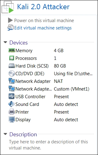
As the preceding screenshot shows, we now have two network cards in our Kali Linux machine: one connected to the VMnet8 NAT switch and the other connected to the VMnet1 Host-only switch. This provides us with direct access to these two networks without having to configure any additional settings. As we have mentioned, we will use the VMnet1 switch for testing, and once the testing is complete, we will place the target in the location required in the architecture and then carry out the test on this.
We have mentioned it before, but it is worth repeating; you have to attack the target on a flat network and verify whether it works. Otherwise, putting a filter in place will just be a waste of time.
We will now look at a simple example. In your Kali virtual machine in VMware Workstation, click on Power on this virtual machine to start the virtual machine. Once the machine is loaded, you will log in by clicking on Other. This will bring up the login page for the machine. Enter root as the username and toor as the password. Once the desktop comes up, navigate to Applications | Accessories | Terminal to open a terminal window. In the window, enter ifconfig eth1 to view the IP address information for the interface that is connected to the switch.
Before we do anything else, we will update the Kali distribution. A note of caution here: sometimes, the update will get errors, so before we perform the update, it is highly recommended that we take a snapshot of the machine. In VMware Workstation, navigate to VM | Take snapshot. In the window that opens, enter a name for your snapshot and click on Take snapshot.
As we have discussed, in VMware, the host will be the first IP address of the subnet, so the host for us is 192.168.10.1. Now, we will conduct a small experiment. We are going to use the popular tool, Nmap, and scan our host. We want to ensure that our firewall is disabled on the host. In the terminal window, enter nmap -sS 192.168.10.1 and scan the host machine. When the scan is complete, you should see results similar to the ones shown in the following screenshot:
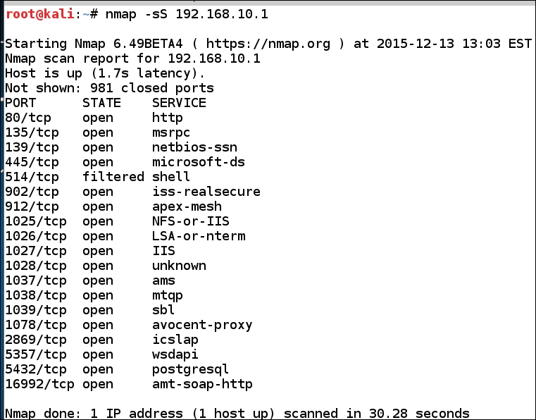
As we can see, the host has a number of ports that are open on it, but now we want to turn the firewall on. Once you have turned the firewall on, conduct the same scan again. You will now see that as the firewall is on, the results are different. This is the thing that many who do testing do not understand; this is the Windows firewall and we used to consider it easy to penetrate, but as our little experiment has just shown that is no longer the case. If you search around the Internet and look for guidance on how to penetrate a firewall, you will read about fragmentation scans and a number of other methods. You are encouraged to try all of these different techniques on your own, rather than cover each one of them here; we will go to the creator of Nmap, Fyodor. He has some advanced scanning references, and one of those is actually a book. So, as we look around, we find that to penetrate a firewall it is recommended to use a custom scan. As with anything you read about, the process is to create a lab environment and then test and verify for yourself. In your terminal window on Kali, enter nmap -sS -PE -PP -PS80,443 -PA3389 -PU40125 -A -T4 10.1.0.1.
This will conduct a scan using a number of additional parameters that are reported to get through a firewall. We will not cover each one of these options here, but encourage you to read the man page and explore what each one of these options do. Additionally, you might want to run Wireshark and see what the scan is doing at the packet level. Once you have run the scan, was it successful? An example output of the scan is shown in the following screenshot:
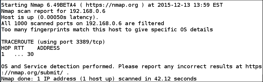
As the previous screenshot shows, there really is not much information gathered from the scan. So, the claim that this can penetrate the firewall does not work, at least, not against the Windows firewall. This is something that we, as testers, have to understand. If the environment is well configured and the firewall has strong rules for both ingress (inbound) and egress (outbound) traffic, it can present a formidable target. This is not a bad thing; in the end, we all want to improve the security posture for our clients. Unfortunately, from a security standpoint, there are always weaknesses in the majority of the architectures that we come up against. While this is bad for security, it is great for our testing!
An example of an architecture with a router as the perimeter device is shown in the following diagram:
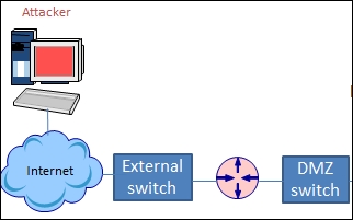
As the previous diagram shows, in our architecture, the first level of defense that we encounter is the router. There are a number of different devices we can encounter, and if we have the luxury of a lab environment that is not mobile, we can use actual physical devices. A source that I am sure many of you know about is auction sites such as eBay that help to pick up used equipment at a reasonable rate. Another site that I have personally used many times to get used Cisco devices is http://www.routermall.com. What I like about the site is that you will get cables and also the IOS software when you purchase equipment from them. As we have said before, we are more concerned with building a pen testing lab that we can carry on our laptop, so a physical router will not provide us with that capability. Therefore, we have to look at solutions that we can place into a machine and either emulate or perform the functions of a router for our architecture.
While it is true that we can make any machine into a routing device using the packet forwarding capability of the device, this is not the only thing we want to accomplish with our routing device. When you encounter a perimeter device in your testing, that device will more than likely have some form of filtering on it. Therefore, we want our chosen router component to have the capability to perform some form of filtering.
The one solution we want to share with you is the Cisco router emulation software, Dynamips, originally written by Christophe Follet in 2005 and maintained until 2008. The original Dynamips software is no longer maintained, but for our purpose, the last release will provide all of the functionalities that we will require. There is one requirement to use any of the Cisco emulators, and that is that you have to have a version of the Cisco IOS to access and boot. We will offer an alternative solution in the next section to those who do not have the capability to obtain a Cisco IOS image.
From this point forward, we will work with the Dynamips software and then the text-based frontend that is Dynagen. For those of you who want a GUI-based interface and also the latest version of Dynamips, you can go to https://www.gns3.com/ and get the required software there. Additionally, you can get numerous resources and documentation on the software, and not only does it provide for Cisco devices, but also for Juniper devices. It is an excellent reference to proceed with your development of labs to emulate a variety of devices. The software also has a Windows installer package and you can run the emulator within a Windows environment.
Enough discussion on this; let's build a router! We want to use Ubuntu as our router emulation software platform. You can go to the Ubuntu website and download the software from http://www.ubuntu.com/download/desktop. The latest stable version at the time of writing is 16.04, and this is what we will be using for our router platform. There can be some challenges with the 64-bit version; for our purpose, both the 32 or 64 bit version will work.
Once you have downloaded the ISO image, you will create a new machine in VMware Workstation and mount the ISO image. We covered the steps in Chapter 3, Planning a Range, so you should be familiar with them. If not, you can refer to the chapter for the exact sequence of steps. VMware Workstation will more than likely recognize the ISO image and offer to perform the easy installation. This is something that you can accept, or not, depending on personal preference.
After you have created the machine and booted from the ISO image, you will work through the installation prompts and install the software into the hard drive of the virtual machine. For the most part, you can accept the defaults for the installation, but feel free to make changes as needed. Remember, this is one of the advantages of virtual environments. If we blow something up, we can create another one, or as we discussed, if we have taken a snapshot, we can restore to that. A great thing about Ubuntu is the ability to add packages once the installation has been completed.
When the installation completes, the virtual machine, by default, will have one network adapter connected to the NAT switch, but as we have architected our design, we know that we need two interfaces on our router. This is to provide the connectivity, as shown in the following diagram:
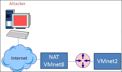
To create our architecture with the Ubuntu machine, we have to add a network adapter and connect it to the VMnet2 switch. With VMware Workstation, you do not have to shut the virtual machine down to add a new adapter. In the software, navigate to View | Console View to bring up the configuration view for the virtual machine. Click on Edit virtual machine settings and add a network adapter and connect it to Vmnet2.
Now that we have the configuration set for our router machine, we need to get an IOS image and copy it into the machine. As we have mentioned, if you do not have access to an IOS image, you will not be able to use the Dynamips tool. In the next section, we will provide a solution that does not require access to an IOS image and provides the same functionality of filtering that we require.
The Dynamips software is available from the software repository for Ubuntu; in your Ubuntu machine, open a terminal window by clicking on the terminal icon on the menu bar on the left-hand side of the screen. If you do not see the terminal icon, you can click on Ubuntu Software Center and search for it.
In the terminal window, enter sudo apt-get install dynamips. This will fetch the Dynamips software and install it. Once we have installed it, we will then install the frontend application for the tool. Enter sudo apt-get install dynagen in the terminal window.
To stop having to type sudo for each command, enter sudo -i. The configuration files that we use to configure our router are copied to a rather long path, and we will fix this now. We will use the example configuration file, simple1.net. Enter cp /usr/share/doc/dynagen/examples/sample_labs/simple1/simple1.net /opt/config.net.
Now that we have the configuration file copied, let's take a look at it. Enter more /opt/config.net. An example of the default configuration file is shown in the next screenshot:
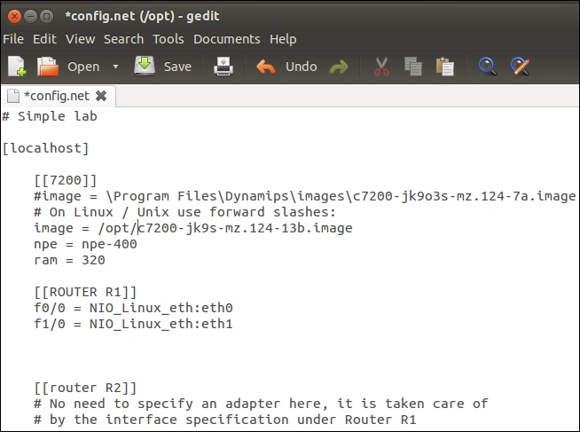
There are two areas we will concentrate on for our configuration. In the section for the router image, we have to specify the path to the IOS image on the system. The second area is the router section. In the example, we are going to use the name R1 for the router, and as you can see, the router R1 has one serial interface that is connected to the serial interface of R2. This is a two-router sample configuration, and for our purpose, we do not need so many routers. You are welcome to explore different configurations, but in this book, we will concentrate on just having one router, as this is our perimeter device we have identified in our design.
We want our R1 router configuration to have two network interfaces; one will connect to the VMnet8 NAT switch and the other will connect to the VMnet2 switch. Consequently, we have two network cards on the Ubuntu machine that are configured in this manner, so it is just a matter of entering the configuration for the interfaces into the config.net file. We have to enter the configuration that will recognize the interfaces; this is what is known as a tap interface, and this is beyond the scope for us to discuss here. However, if you would like to find out more, refer to http://www.innervoice.in/blogs/2013/12/08/tap-interfaces-linux-bridge. Open your config.net file by entering gedit /opt/config.net. Change the path to the path of your IOS image file as required, and then in the R1 router section, enter the following in the place of the current serial interface:
f0/0 = NIO_linux_eth:eth0
f1/0 = NIO_linux_eth:eth1
This will connect the fast Ethernet interfaces to the interfaces of the Ubuntu machine. One other setting you may want to change is the RAM allocation. The default is at 160 MB, and this is a little low, so I recommend that you increase it to 320 MB.
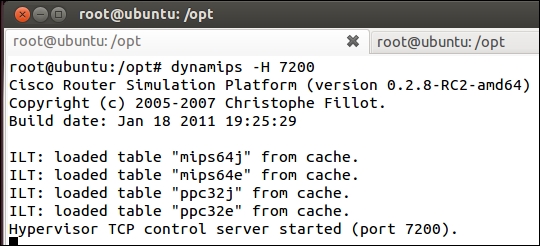
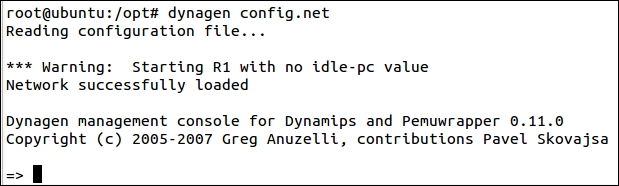
It is also a good idea to comment out the R2router as we are not using it. We are now ready to test our configuration. In a terminal window, enter dynamips -H 7200. This will start the Dynamips server on port 7200. If all goes well, you should see an output similar to that shown in the following screenshot:
The next step is to start our configuration file, and that will interact with the Cisco IOS that we have loaded on the machine. The example IOS image we are using in the book is for a 7200 series router, so we can configure a number of interfaces on it. However, for our purpose, we need just the two fast Ethernet interfaces to perform our routing, and more importantly, as we progress the filtering of traffic between the segments of our architecture.
In another terminal window, enter dynagen /opt/config.net. This will read the configuration file we have created and load the IOS image for access. Hopefully, you will not encounter any errors here, but if you do, then it is time to troubleshoot. The most common error is a typo in the path. If it is a path error, you will see a message that says the image could not be found. An example of what you should see is shown in the next screenshot:
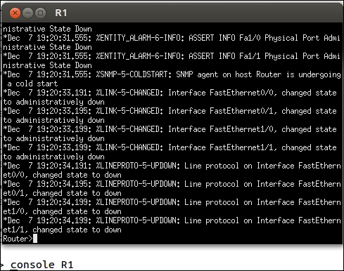
At this point, we are ready to connect to the router R1; you accomplish this by entering the console R1 command in the Dynagen prompt. This will log you in to the router as if you were connecting via a console cable. You should see another window open. This is the access to the router. Pressing the Enter key should bring you to a login prompt, as shown in the next screenshot:
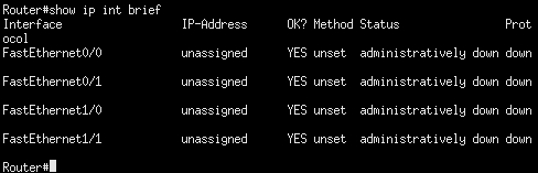
From here, it is a matter of using router commands to configure the two interfaces for our router; enter en at the router prompt to enter privileged mode on the router. Once you are in privileged mode, enter show ip int brief to bring up the interface configuration of the router. You will see that there is no interface configuration yet, so we have to configure it. An example of the output of the command is shown in the next screenshot:
We now want to configure these interfaces (f0/0 and f1/0), as they are currently not set. We do this with the global configuration from the terminal option. To access this, enter conf t at the router command prompt. This will place you in the configuration mode. Enter int f0/0 to access the interface configuration menu and enter the IP address 192.168.80.10 255.255.255.0. This will create a configuration for the f0/0 interface that will connect to our VMnet8 NAT switch. To bring up the interface, enter the no shut command. Once we have done this, we will do the same thing for the next interface. In the prompt window, enter int f1/0 to access the configuration menu for the f1/0 interface. Next, we have to configure the IP address that is connected to our VMnet2 switch, so enter the IP address 192.168.20.10 255.255.255.0. In the interface configuration window, bring up the interface by entering no shut. We should now have the interfaces all configured. To return to the main router prompt, press Ctrl + Z. Verify your configuration by entering show ip int brief. Next, we will verify whether we have connectivity on the VMnet8 switch by entering ping 192.168.20.1.
The next thing we will do is save our configuration; this is also one of the most important things. To do this, enter write mem. You might know of an alternative method, and that is the copy run start command.
We now have a complete Cisco 7200 router on an Ubuntu machine, and we can configure anything within the IOS that we want, such as IPsec and other things. For now, we will stop with the Dynamips tool and move on, for those of you who want a solution without having to get a Cisco IOS image. In your Dynagen prompt, enter stop R1 to bring the router down.
For those of you who do not have access to a Cisco IOS image, we can accomplish what we need to for our architecture with pretty much any Linux or Unix machine that you want to use. As we have used the Ubuntu platform for the first example, we will use another one here. The intent is to have filtering capability, and we can achieve this by using an OS that has the iptables software installed. We will use a Debian distribution to accomplish this task. You can download Debian from the official Debian site at www.debian.org. Once you have downloaded the image, you will need to create a virtual machine and run the installation process. After you have installed the OS, you will need to configure the network. One installed network adapter will be on the VMnet8 NAT switch and the second one will need to be connected to the VMnet2 switch.
Our configuration for the two virtual switches we have created provides us with a DHCP server to assign IP addresses, but as this is going to function as a router. It is better to set a static address for the interfaces as this will allow us to have more granular filtering rules when we create them. Moreover, we don't have to change settings each time we boot the machine as the addressing will not change like it does with DHCP.
The Debian distribution uses a configuration file to set the parameters that you want the network card to have once you boot it. Using an editor of your choice, open etc/network/interfaces; we want to configure our two network interfaces, eth0 and eth1:
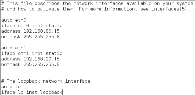
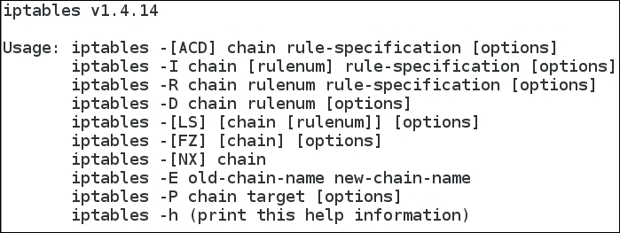
We could have configured the same addresses that we used in Dynamips, but then if sometime in the future we want to run the Debian and Ubuntu machines at the same time, we would have an IP address conflict. Therefore, it is always a good design decision to plan for this possibility and configure unique addresses. We want to use the IP tables' tools to execute our filtering, boot the Debian machine, and log in. To verify whether iptables is installed, in a terminal window, enter iptables -h to show the usage of the tool. An example of the output from this command is shown in the next screenshot:
We now have successfully set up the Debian machine, and the next step is to configure the IP tables to support the filtering that we need. This is something we will do when we start testing the devices.
Now that we have configured and set a router, the next component in our architecture is a firewall. As with the router options, there are many options that we can choose. First, let's take a look at our network architecture with respect to the firewall. This is shown in the next diagram:
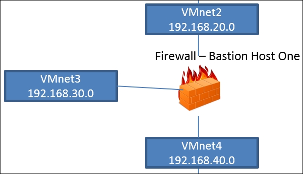
In our initial architecture we have two firewalls, and again it is a matter of choice what you use for these Bastion Hosts. A recommendation is to use different software and/or products since we want to be able to practice against a variety of targets; furthermore, if you are building a home lab then you can use actual devices. In my lab, I have a Cisco ASA, Juniper, and a Fortinet, because I have encountered each of these in my testing. For now, we will configure the first firewall Bastion Host One.
As shown in the previous diagram, we have three interfaces on our Bastion Host that serves as our firewall; this will require us to connect to three switches. The firewall we are going to use is the free version of the Smoothwall firewall.
Again, an important point here is that the firewall you put into your architecture is sometimes determined by the contract you are planning for. Therefore, our intent here is to provide a firewall so that we can test a number of different configurations when we are practicing against different vulnerabilities that we have found during our research. You can download the ISO image for the Smoothwall firewall from http://www.smoothwall.org/download/.
Once you have downloaded the ISO image, create a virtual machine. We want this machine to have three interfaces to provide us with the connectivity that we require to meet our network design. An example of this configuration is shown in the next screenshot:
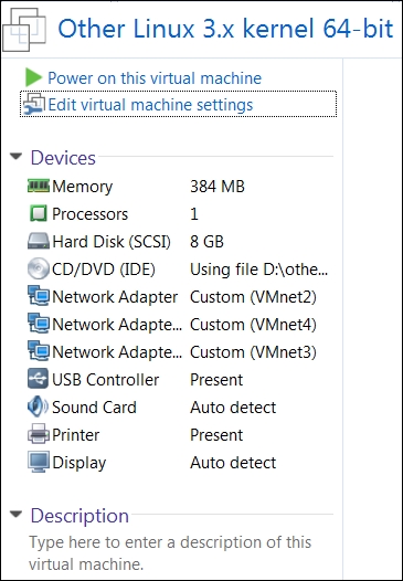
This machine requires three network cards, and each of these cards will be connected to the Bastion Host One interfaces, which are as follows:
- VMnet2-eth0-Red
- VMnet4-eth1-Green
- VMnet3-eth2-Orange
When you boot the machine, the installation package will start. Read the explanation of the different steps and accept the defaults for the installation process. Accept the default configuration of half-open. This setting will install the prudent approach to security, that is, nothing is allowed without explicitly defining it in most cases.
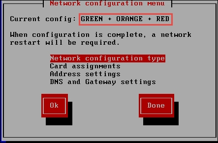
In the Network Configuration type, we want to change the configuration to match the required switch design, that is, green, orange, and red. In the network configuration window, select GREEN + ORANGE + RED and then press Enter. Verify your connection settings, as shown in the next screenshot:
The next thing we need to set is the card assignments; when you select this, the network configuration we have created will be probed. So, each time a network card is detected, it will assign it to an interface. The order of the interfaces will be Red, Green, and then Orange. So we need to assign them in this order as it will match eth0, eth1, and eth2, respectively.
Once all the cards have been assigned, the next thing to do is set the IP addresses. The IP addresses will be configured as follows:
- Red: DHCP
- Green:
192.168.40.20 - Orange:
192.168.30.20
Once the network cards have been assigned, you will then be prompted to set two passwords: one for the remote access and the other for the root user. I recommend that you make them easy to remember as this is only for a testing environment. I usually use the name of the user followed by pw. So, for the root user, the password would be rootpw. You are free to set any password you like. After you have set the passwords, the system will reboot. Once it reboots, you will have to log in and verify that the three interfaces are set as we intended. Once you have logged in, verify that the interfaces are configured as shown in the next screenshot:
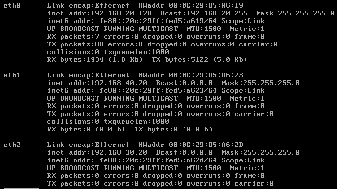
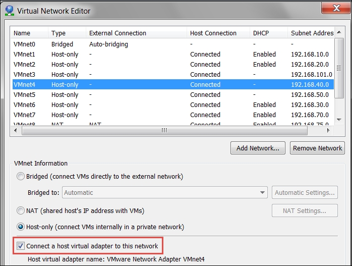
The preferred method is to access the configuration from the green interface via a web browser. We can set up another machine on the VMnet4 switch, or another method is to use the host for our configuration. To have this capability, we have to connect the switch to the host. In VMware Workstation, navigate to Edit | Virtual Network Editor | VMnet4 and select the Connect a host virtual adapter to this network. An example of the completed configuration is shown in the next screenshot:
The next step is to open a browser of your choice and enter https://192.168.40.20:441; this will open the web login interface. Enter the username of the admin with a password that you configured during the installation. Once you have logged in, you will be in the main menu of the firewall. Navigate to Networking | Incoming, and this will show the rules that are configured for inbound traffic. An example is shown in the next screenshot:
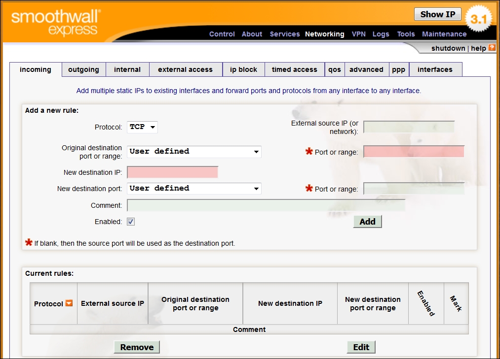
The previous screenshot shows that, by default, Smoothwall does not allow any initiated traffic to come inbound; this is the way an architecture should start. Then, the process is to add the protocols that an organization wants to allow by policy. For our purpose, when we want to test something and place it in the orange interface, we will have to place a rule for that here. If we want to go to the internal network or the green interface, then it will not let you configure that unless you force it. This is because from the outside, no connections should be allowed to the inside. By using this platform, we now have a well-configured Bastion Host that is closed by default. The next thing we want to look at is the outgoing, or egress, traffic. Click on outgoing to bring up the configuration.
An example of this default configuration is shown in the next screenshot:
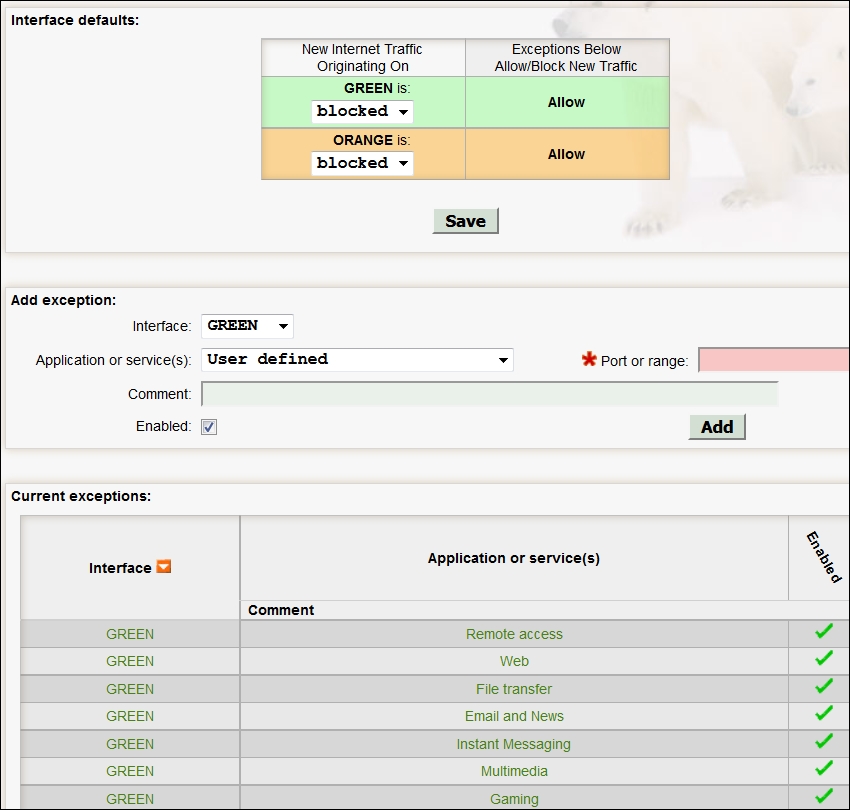
The default configuration allows any machines on the green interface to access any of the services that most network users would need. This is the power of a half-open installation; it allows us to bind all of the ports we need on the inside interface of the firewall and then have no ports open on the outside interface, with the exception of the ones we require to meet the needs of our security policy.
For now, we will stop here, as we have covered the main configuration of the firewall as a Bastion Host One, and it is time to move on to another topic. You are encouraged to experiment with the firewall and test it as you feel necessary. One good way to test it is to bring up the hacking tool of your choice and set the target as the interface on the Bastion Host's red interface.
We now have our architecture built, so it is time to add components to it for our testing. This again is something that will largely be dependent on the results from the testing methodology that we follow. That being said, we want to have a number of different web servers to test and practice against. In Chapter 3, Planning a Range, we downloaded and used the broken web application virtual machine from the OWASP group. So, we have an excellent web server there. Next, we will download another vulnerable web server to practice with. We want to download and use the virtual machine metasploitable that is provided for us from Rapid7. You can download the virtual machine from the following link:
https://information.rapid7.com/metasploitable-download.html?LS=1631875&CS=w
You will have to register to download the application. Once you have downloaded it, open the virtual machine and add a network adapter that is connected to the VMnet1 interface. As with most virtual machines, the network adapter is set at the VMnet8 interface by default, and we can use this for the direct testing. Any time we want to move the web server to another location of our architecture, we just change the switch to which the adapter is connected. Additionally, we could take a snapshot and have one for each location we want to test with the machine; furthermore, we could clone the machine and have clones around our architecture. It really does not matter how we do it. The intent is to have machines to test our skills and then place obstacles around or between us and the target and learn methods to get past them.
Once you have the machine running, log in to the machine with a username of msfadmin and a password of msfadmin. Once you are logged in, note the IP address and open a browser and connect to the web server on the machine. An example of the home page of the machine is shown in the next screenshot:
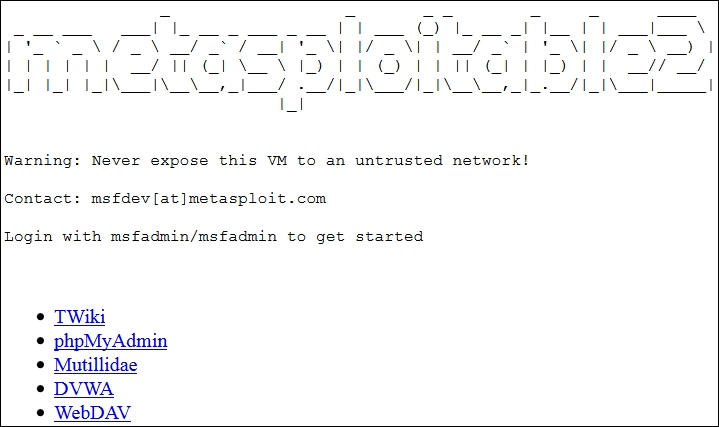
As shown in the previous screenshot, the metasploitable virtual machine provides us with multiple testing sites; we have Mutillidae, Damn Vulnerable Web App, and many others. This will provide us with a multitude of techniques to test on the network.
For now, the metasploitable machine in combination with the virtual machine we downloaded will suffice for now. There are a number of components we still need to build into our network architecture, and we will address them in later chapters throughout the book.