
The alarm system, in this case the BeagleBone, must be able to monitor the world around it. It does this by using ICs called comparators. You can think of a comparator as an op-amp with extremely high gain. Like an op-amp, when the voltage on the positive (+) input is higher than the voltage on the negative (-) input, the output goes high. When the opposite is true, the output goes low.
We will be using an LM339 comparator. I chose the LM339 comparator because it has been around forever, and still comes in through-hole DIP packages. It is cheap and easy to source. Best of all, it is hard to blow up! The device has an open collector output. What this means is, a resistor is required to pull the output high. By connecting the output pull-up resistor to 3.3V, we now have a level converter that can be safely connected to the BeagleBone.
In the following diagram of the single zone comparator circuit, a 4.7K ohm resistor—R5 is used as a pull-up. The LM339 comparator can sink plenty of current; so for debugging purposes, we will also connect D1 and R6 to the output. That way when the comparator is triggered, D1 will turn on. The other handy feature of the open collector output is that you can connect them together without damaging the output. This is often called a logical OR.
The following circuit diagram actually monitors for two different conditions. If condition 1 is true, then pin 2 goes low or if condition 2 is true, then pin 2 goes low.
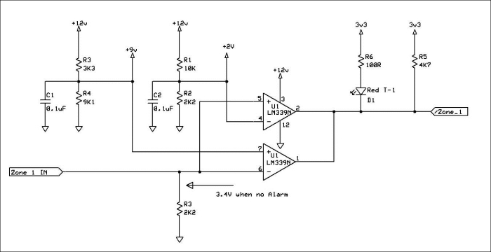
Single zone comparator circuit
The previous diagram is for one zone. In this project book, it is replicated four times for four zones. However, readers are free to replicate this circuit for as many zones as they have inputs on their BeagleBone.
An end of line resistor is a resistor that is installed in the last device (sensor) of a chain of devices; hence the term end of line resistor.
Resistors R4, R3, and the end of line resistor (marker EOL on the schematic) form a voltage divider. Basically, you have 5.6K and 2.2K in series and they are connected to 12V. Therefore, Ohm's law tells us that there will be about 3.4V at the plus input of the comparator when the alarm contacts are closed.
Resistors R1 and R2 form a voltage divider that provides a 2V reference for the negative input. As we learned before, if the plus input (3.4V) is higher than the minus input (2.0V), then the output will be high.
If the alarm condition occurs and the switch opens, then the 2.2K resistor, R3, will pull the input to 0V and the output will be low because the input is now less than 2.0V.
This also happens if the wire is cut by a burglar.
The following diagram shows what happens when the circuit is opened, either by an alarm contact or by a cut wire.
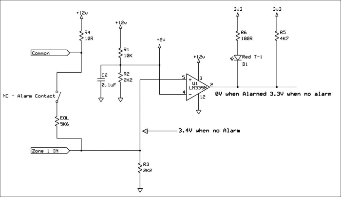
Open circuit condition
The following diagram shows what happens when someone or something shorts out the alarm contacts.
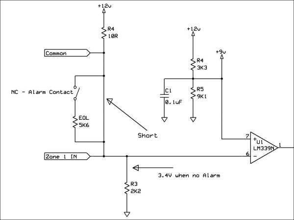
Contacts shorted
What if the burglar tries to jumper the alarm contacts and shorts out the EOL resistor?
In this case, the minus input of the LM339 comparator goes higher than the positive input, and once again the output is pulled low. Then, the reference voltage (9.0V) is applied to the positive input, and the sense voltage is applied to the minus input. If the EOL resistor is shorted, then 12V is applied to the minus input of the comparator, and the output is pulled low, once again. As we have learned before, the outputs of the two circuits are logically ORd together, so that if either an open circuit or a short circuit occurs, the alarm will be triggered.
I could have split the circuit into two different signals for each zone. One to indicate a short circuit, and one to indicate an open circuit. But, in order to reduce the number of inputs to the BeagleBone, I have connected the two outputs together. It also makes the software less complex. If you are a good programmer, you could use two inputs for each zone, but you would also have to change the PCB.
You may have also noticed that there is a considerable difference between the sense voltage and the reference voltage. This is to allow for long runs of wire, and for those of you who like to use Google. It is called hysteresis.
Tip
If you have a professionally installed alarm panel or know someone who does, open the panel and look at the terminal blocks where the wires are attached to the panel. If you see the resistors connected across the screw terminals with wires connected to them, the alarm system was NOT installed properly! What you do about this is up to you. The end of line resistors are called that for a reason! They belong at the END of the string of contacts. Installing them in the panel is a lazy way of doing things, and does nothing to protect the contacts from being bypassed.