
In the previous chapter we built a simulated one zone alarm. Now we will learn how to install and wire basic sensors. Things such as window contacts, passive infrared sensors (PIRs), and glass break detectors. We will also learn about the most important part of any alarm system installation.
This is by far the most important part of the installation. Poor planning has caused more headaches than any other part of an alarm system installation project.
As the name suggests, take a walk around the property you will be protecting, both inside and outside. Try to think like a bad guy.
Ask yourself, "If I wanted to break into this house/office/warehouse, how would I do it?"
Take pictures if you think it will help. Make sketches of the inside and outside of the building, so that you can plan where you are going to put your sensors. There are a number of free landscaping CAD programs that will help you with this.
Here is a simple checklist for you:
- How many doors are there?
- What type of doors are they? Garage doors? Human entry doors? Pet doors? (Seriously, burglars have used children.)
- How many windows are there? How many open?
- How many windows are there on the ground floor and how many on the second floor? (Burglars use portable ladders.)
- Is there a hedge or a privacy fence? (Burglars love cedar hedges and privacy fences.)
- Once the burglar is inside, where can they go from there? (Main hallway, kitchen door, or patio door.)
- How many rooms are there that you will have to protect?
- Is everything on the same floor or is there more than one floor?
- What about special alarms? Panic alarm in the bedroom? Smoke alarm in the kitchen? Flood alarm in the basement?
- Hopefully, I have given you plenty to think about and we can now move on to step 2.
For the sake of this book we are going to protect your dream home. You just inherited a fortune from your long lost auntie, and you don't want the bad guys making off with your new found wealth.
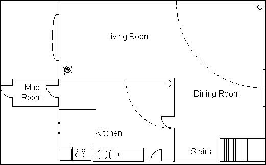
The following diagram depicts the first floor of your dream home:
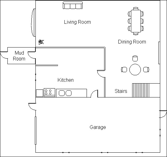
First floor
From your walkabout you noted that:
- There are two entrance doors with a mud room in between.
- There is a patio door off the dining room.
- The garage has two entry doors plus a large garage door.
- There is an entry door from the garage into the kitchen.
- The garage also has four windows, three on the side and one at the back.
- There is a kitchen window and a large bay window in the living room.
- Stairs lead up to the second floor, which has a landing at the top.
The following diagram depicts the second floor of your dream home:
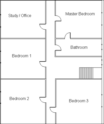
Second floor
From your walkabout you noted that:
- There is the main hallway off the second floor landing.
- All of the bedrooms and the study are accessed from this main hallway.
- Each of the bedrooms and the study has a window.
- There is also a window beside the second floor landing and in the bathroom.
- The bathroom is accessible from either the hallway or the master bedroom.
- Now that we have all this information carefully gathered, it is time to start planning our defenses in earnest.
We are going to employ what the military calls a layered-defense technique. It is exactly what it sounds like.
So here is what we are going to do:
- We are going to plan a layered defense that uses different kinds of sensors.
- For this chapter we will only concern ourselves with the inside of the house.
- The exterior will be covered in the future chapters.
- Let's start with the garage.
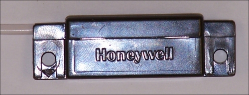
Our first layer will be the doors and windows. There are three personal doors on which we can use simple magnetic switches. The garage door requires a special type of magnetic switch because garage doors tend to move too much and would cause false alarms if we used a small magnetic sensor.
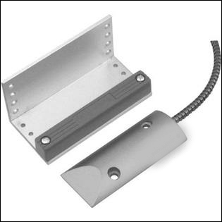
Magnetic garage door sensor
The next layer will be the motion sensors. In this case I would install a PIR sensor in the lower right-hand side of the garage. This way it can monitor all three doors plus the windows.
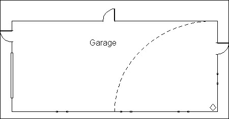
Garage PIR protection
Now that we have the garage protected, it is time to look at the rest of the bottom floor. Once again we will use a layered approach, by first protecting the door and windows. You will notice that the house has a vestibule or mud room as they are sometimes called. This is a good place to put a key switch that turns off the alarm. There is also hardware support for a second key switch, so you might want to install one by the kitchen door to the garage.
The outside door and inside door can be protected with standard magnetic door switches. As part of our layered-defense strategy, I would also put a door sensor on the door leading from the kitchen to the dining and living room area. This increases the chance of catching a burglar who has defeated the window or door sensors. To be clever, I would put it in the same zone as the PIR sensor. That way, if the perimeter is bypassed, the door will still be alarmed.
You will notice that off the dining room is a patio door. You can probably protect this with a standard door sensor. Depending on how large the door is, you may have to use a sensor like the one for the garage door.
Our final challenge is the bay window in the living room. Some of these windows have small side windows that open. These should be protected with door/window sensors. If you have the funds, you might also want to install a glass break detector in case someone puts a brick through your front window. You can put the glass break sensor on either the window switch zone or PIR zone. It will probably come down to whatever is easiest from an installation perspective.
The second layer of protection is once again the passive infrared motion sensor.
What I would suggest is a PIR sensor in one corner of the living room and another in the kitchen. The kitchen one will guard the entrance from the mud room as well at the one from the garage and from the patio doors.
Living area PIRs
Now that we have finished protecting the ground floor, it is time to move upstairs. At this point you have a decision to make. You can continue with the layered-defense approach on the second floor and install alarm contacts on the windows, or not. I'll leave that decision up to the reader, because it may be a monetary one.
At the very least you should have PIR at the top of the stairs and one covering the main hallway. Depending on what you use your study for, you may want an alarm contact on the hallway door and a PIR sensor inside the study.
Anyone trying to break in through bedrooms 2 or 3 should be caught by either the PIR sensor at the top of the stairs or the one covering the main hall. The main hall PIR should be installed outside the master bedroom so that it looks down the hallway.
Before we move on to the installation step, I have a really simple alarm sensor you can make yourself that is just as good as the expensive ones you see in the department stores.
You have probably seen large items like BBQs, patio furniture, lawn mowers, and the like with a cable running through their handles so that they are all strung together. Here is how to make one of your very own for the price of some speaker wire and a resistor!
Simply solder a 5.6K ohm resistor across the two ends of the speaker wire. Now you have a loop with an end of line resistor that you can hook to your alarm system. (Or just twist the wires together if it isn't the end of line.)
Simply thread the speaker wire through whatever you want to protect. For example, the rear wheels of your bicycles or the handle of your BBQ. Put the resistor end in a tamper proof box of some sort and fasten it to something solid. Connect the other end of the wire to your zone. If you will be using the loop outdoors, I would suggest potting the resistor in epoxy or silicone rubber.
You now have the same system as a big box store, at a fraction of the price!
Wire loop sensor
In this step we will be doing the actual installation and wiring of the sensors. It is in this step that your carpentry skills will be put to test.
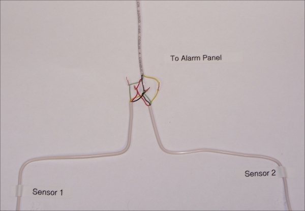
This wiring method is for any non-powered switch, for example, door and window contacts, the garage door contacts, or the loop sensor. The sensor itself is not powered, so connecting them in series is simple.
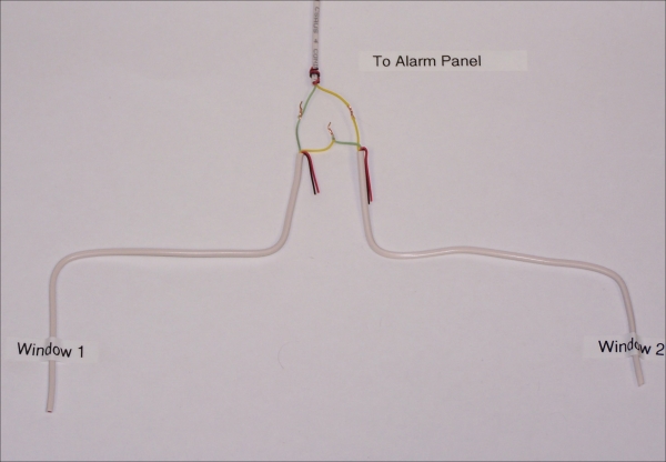
Switch wiring
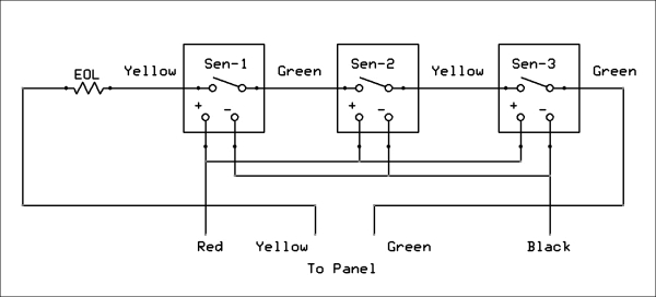
The previous photograph and the following diagram show how this is done:
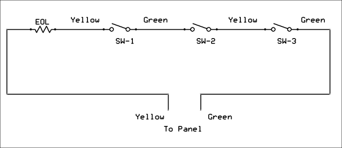
Switch wiring (schematic)
As you can see, you simply keep connecting the yellow wire of one set of contacts to the green of the next, until you have all of the contacts wired in series.
Sensors such as PIRs, glass break detectors, and smoke detectors require power. This makes them a bit more complex to install. If you are following my layered-defense technique, then there will never be a need to have active sensors (PIRs) and passive sensors (window contacts) in the same zone.
Active sensor wiring
The only difference between the two wiring examples is that the power is connected in parallel and the contacts are connected in series.
Sensor wiring (schematic)
These two examples use the least amount of wire. If you have plenty of wire, then pull all of the sensor and contact wiring back to your panel and make the connections there.
This is a more professional way of doing it, but it requires more wire and more wire fishing.
If I was wiring a new home with only bare studs visible, this is the way I would do it.
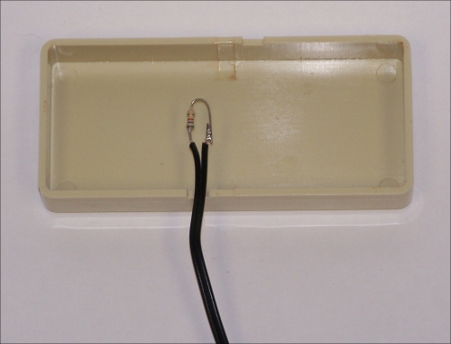
The following photographs show how to install the end of line (EOL) resistor in the window contact assembly.
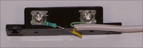
EOL resistor outside a door contact
Wrap one of the resistor leads around one of the screw terminals and solder it to the yellow conductor of the wire leading to the contacts. Wrap the green wire around the other terminal. Keep the wires as short as possible so that they can be tucked neatly into the case of the contacts.
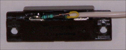
EOL resistor inside a door contact (bottom view)
Here, we see the end of line resistor neatly stowed into the case of the window contact.
Assembled window contact (top view)
The idea is that once the contacts are mounted onto the door or window frame, the contacts with the EOL resistor will look exactly like all of the other contacts and the burglar will have no idea which set of contacts contains the end of line resistor.
The only difference between wiring a door or window contact sensor and an active sensor is that you must also connect power to it. You may have noticed that I have been using yellow and green for the contact wires. That is because we are now going to use red and black for power wiring.
The red wire is connected to the +12 volts at the panel and the black is the negative.
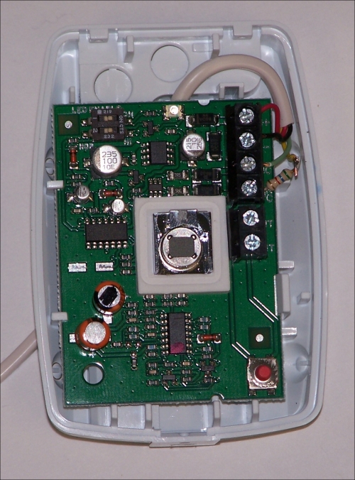
PIR with EOL installed inside
The preceding photograph shows the inside of a PIR sensor with an end of line resistor installed. Many sensors come with an anti-tamper switch built in. This is the small red button you see in the lower-right corner of the PCB. The contacts marked TAMP are connected in series with the alarm contacts. That way if anyone opens the case, the alarm will sound. So there is no need to hide the end of line resistor.
Any of the other types of sensors you are likely to install will be the same as the PIR sensor. The only difference is that CO and smoke detectors may not have anti-tamper switches.
The software consists of two modules, which you will find in the Cloud9 directory. For those of you who don't know, you access the Cloud9 IDE by entering <bone I/P address>:3000 in your web browser.
In my case it looks like, 192.168.10.105:3000.
The two modules are called Alarmpnl.js and Alarmpnl.html. In order to run the software, simply select Alarmpnl.js from the menu and click on Run.
In the console at the bottom of the screen you will eventually see a message telling you the IP address of the web page that it loaded. Again in my case it is 192.168.10.105:8000. This is because the software is using port 8000.
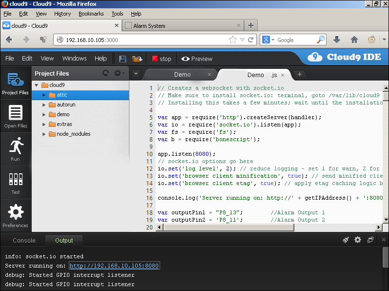
Software running in Cloud9 IDE
In the following screenshot, we see the result of copying the IP address from the Cloud9 console into the tab of a web browser. You can do this by simply double-clicking on the blue text. This will open the page in a new tab of your current window.
Note the address in the browser bar.
The software uses port 8080 of the BeagleBone IP address, which in my case is 192.168.10.105.
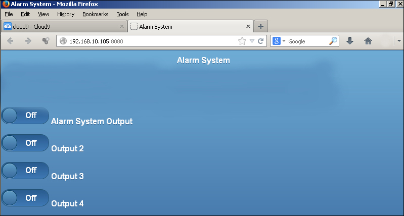
Software running in Cloud9
What the JavaScript software does is wait for an input pin on the bone to go low and then turns on the output one, which in this case is labeled Alarm System Output.
You can do a couple of things with this output from the web page. Clicking on the button twice (not double-click) will turn off the siren if an alarm has been detected and you want to cancel it remotely.
On the other hand, you can generate a Panic Alarm condition by remotely turning on the siren. To do this, simply click on the button marked Alarm System Output.
The other buttons control the other three outputs, and as I described in the previous chapter, they can be used to turn on and off various devices in your home or office.
I would suggest that you change the label for the button to reflect what it is actually connected to; for example Front Gate or Emergency Pump.
In order to add more outputs to our system, we must make some modifications to the two pieces of code provided with the book.
First we must modify the JavaScript as follows:
socket.on('Output4', function (data) {
    if (data == 'on') {
       //Turn the LED ON
       b.digitalWrite(outputPin4,1);
       console.log ("LED 4 On");
    } else if (data == 'off') {
       //Turn the LED OFF
       b.digitalWrite(outputPin4,0);
       console.log ("LED 4 Off");
    }
  });
In the code snippet above, outputPin4 is a variable corresponding to an actual pin on the BeagleBone.
These variables were assigned earlier in the code:
var outputPin1 = "P8_13";        //Alarm Output 1
var outputPin2 = 'P8_11';        //Alarm Output 2
var outputPin3 = 'P8_12';        //Alarm Output 3
var outputPin4 = 'P8_14';         //Alarm Output 4
In order to add another output, you would replicate this code and change the highlighted code from output4 to output5 for example, change outputPin4 to outputPin5.
You would then have to add a variable called outputPin5 and assign it to an actual I/O pin on the BeagleBone.
You must also modify the HTML page to add another switch icon to the page.
In this case you must change all references to switch4, output4, and toggleswitch4 to switch5, output5, and toggleswitch5 respectively.
<div data-role="fieldcontain">
<select name="toggleswitch4" id="Output4" data-theme="b" data-role="slider" onchange="Switch4(this);">
  <option value="off">
  Off
  </option>
  <option value="on">
    On
  </option>
</select>
<label for="toggleswitch4">
  Output 4
</label>
</div>
If you want to change the name of the switch as it appears on the web page, simply change the switch <label>. In this case Output 4 could be changed to Pump.
</select>
<label for="toggleswitch4">
  Output 4
</label>
</div>
The code is well documented and you can preview the page before actually running the software. In order to preview however, you have to save the file. So I would suggest giving it a different file name until you are sure it is the way you like it.
Adding inputs is much the same as adding outputs. We must modify the JavaScript file.
First we add a new input pin:
var inputPin1 = 'P8_19';     //Zone 1
var inputPin2 = 'P8_15';     //Zone 2
var inputPin3 = 'P8_9';      //Zone 3
var inputPin4 = 'P8_7';      //Zone 4
var inputPin5 = 'p8_ ?';	    //Zone 5

//Setup pin directions
b.pinMode(inputPin1, b.INPUT);
b.pinMode(inputPin2, b.INPUT);
b.pinMode(inputPin3, b.INPUT);
b.pinMode(inputPin4, b.INPUT);
b.pinMode(inputPin5, b.INPUT);
The next thing we do is add another interrupt handler:
// Setup interupts
b.attachInterrupt(inputPin1, true, b.FALLING, Zone1Callback);
b.attachInterrupt(inputPin2, true, b.FALLING, Zone2Callback);
b.attachInterrupt(inputPin3, true, b.FALLING, Zone3Callback);
b.attachInterrupt(inputPin4, true, b.FALLING, Zone4Callback);
b.attachInterrupt(inputPin5, true, b.FALLING, Zone5Callback);
Now, all we have to do is tell BeagleBone to turn on the alarm siren when the interrupt occurs:
//Alarm Detected in Zone 5
function Zone5Callback() {
  flag4 ++;
  if (flag4 > 1){   //For false alarms on script startup
    console.log ("Alarm Detected in Zone 5");
    Alarm();
    state = 1;
    b.digitalWrite(outputPin1, state);//Turn ON the Alarm LED
  }
}
The software uses a JavaScript package called jQuery and another called jQuery mobile, these two packages allow us to use the web page with mobile devices. An approximation of the software running on a mobile device is shown in the following screenshot:
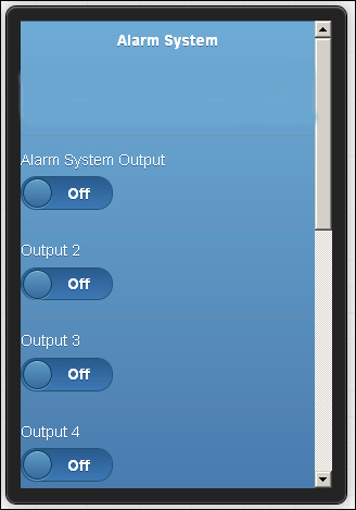
Web page on a mobile device
The following screenshot shows the web page as it might be displayed on a tablet or a laptop:
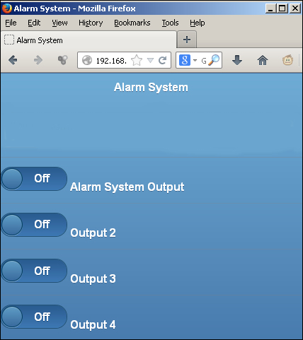
Tablet or laptop display
The table below shows the common I/O pins to both the boards
|
P9 |
P8 | ||||
|---|---|---|---|---|---|
|
GPIO |
Pin # |
Signal |
GPIO |
Pin # |
Signal |
|
30 |
11 |
Not Used |
66 |
7 * |
Zone 4 Input |
|
60 |
12 |
Not Used |
67 |
8 |
Not Used |
|
31 |
13 |
Not Used |
69 |
9 * |
Zone 3 Input |
|
40 |
14 |
Not Used |
68 |
10 |
Not Used |
|
48 |
15 |
Not Used |
45 |
11 * |
Alarm Output 2 |
|
44 |
12 |
Not Used | |||
|
4 |
17 * |
Alarm Output 3 |
23 |
13 * |
Alarm Output 1 |
|
26 |
14 |
Not Used | |||
|
I2C2 |
19 |
Used by Beagle |
47 |
15 * |
Zone 2 Input |
|
46 |
16 |
Not Used | |||
|
3 |
21 * |
Alarm Output 4 |
27 |
17 * |
Key Switch Input |
|
65 |
18 |
Not Used | |||
|
49 |
23 |
Not Used |
22 |
19 * |
Zone 1 Input |