
In the previous chapters we built and tested hardware for our alarm system. If you recall, the basic system came with four optically isolated outputs. If we assume that one output will be used to activate the strobe light and/or a siren (you can hook the two in parallel so long as they are both the same voltage, using a relay as shown at the end of Chapter 4, Building the Hardware), we are then left with three unused outputs. The BeagleBone adapter board also gives us the hardware capability to drive even more outputs. So now I am going to give some ideas about things you can do with these leftover outputs.
The low-current solenoid driver circuit can be used to control things such as the small solenoids used by many lawn sprinkler systems.
The data sheet says that the IC is capable of providing 2A continuously, provided that it has a proper heat sink. Fortunately, we will only be pulsing the solenoid on for about a second, so this should not be a problem.
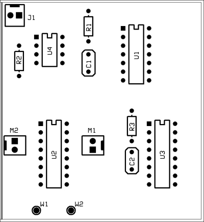
A dual low-current solenoid driver
Our circuit will drive two solenoids at the same time; for example, two sprinklers. We cannot control solenoids separately because we need to keep the design simple and maintain the number of inputs required. Therefore, you will have to turn on both sprinklers at once.
The following circuit is used to drive a single-coil solenoid. This type of solenoid requires a dual polarity pulse to activate it. A positive-going pulse opens the solenoid and a negative-going pulse closes it. In order to do this, we will use what is called a half-bridge circuit. The SN754410 IC is designed to control a full-bridge circuit, so we get two solenoid controllers for the price of one!
The LM555 timer (U4) generates a one-second pulse when it receives a trigger pulse from the alarm board. I used the LM555 timer to save us the trouble of having to generate the trigger pulse in software.
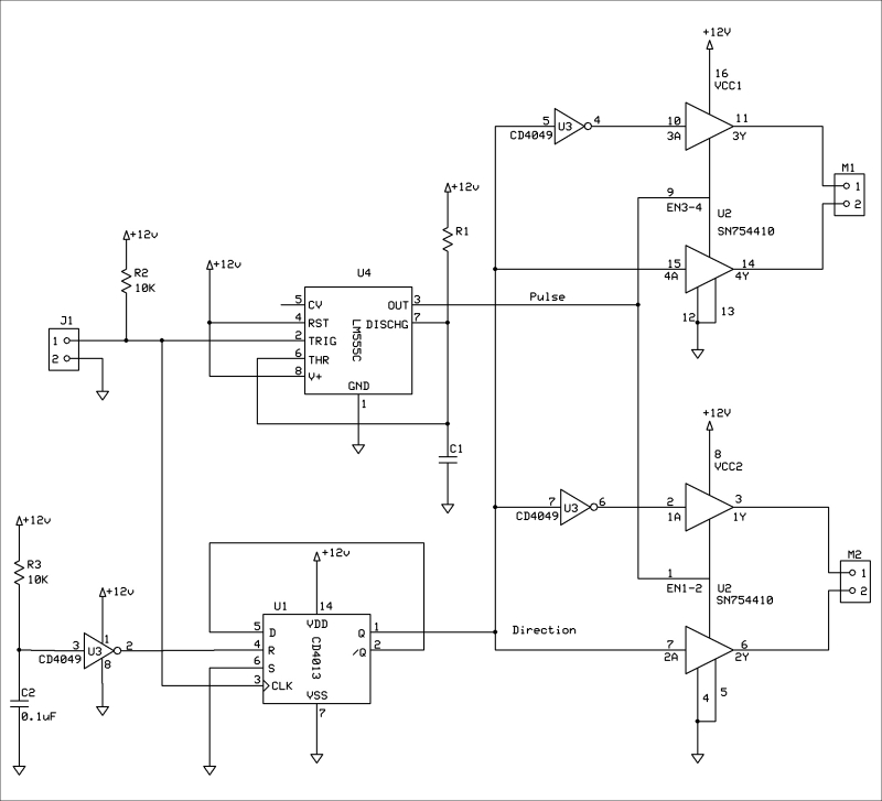
Solenoid driver schematic
As I said before, you have to change the polarity of the pulse to open and close the valve and that is what the CD4013 flip-flop is for. The polarity of the pulse changes every time the circuit is triggered. To generate the pulse, we simply enable the SN754410 IC with a one-second pulse. The solenoids are connected to the M1 or M2 connector.