
The optically isolated output PCB is a very simple construction. There are two reasons why I made a separate board in this case.
This form factor allows for a more modular design. You can have as many outputs as you can find I/O pins on BeagleBone.
It is also cheaper to order small 3.8" x 2.5" mini boards from ExpressPCB than to order a larger custom-size board.
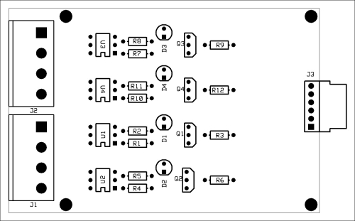
Isolated output PCB
Assembly of this board is very much the same as that of the first board.
- Install the resistors first.
- Install the LEDs, making sure that the polarity is correct.
- Install the transistors, again checking for correct installation.
- Install the ICs preferably on sockets to make repairs easier.
- Finally, install the connectors.
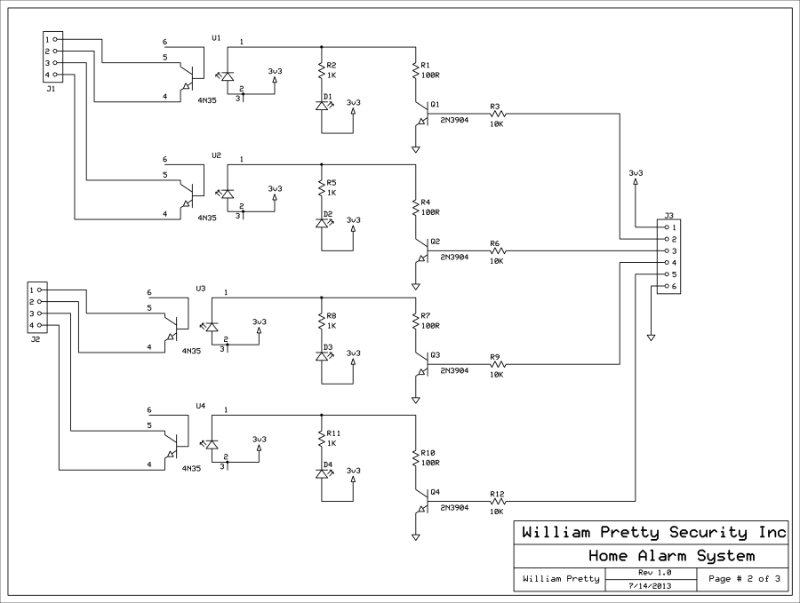
Opto-isolated output PCB schematic
All four circuits are identical. A logical 1 on the input applies 3.3V to the base of the NPN transistor. This turns on the transistor and pulls the collector of the transistor low. This turns on the status LED [D1 – D4] and the LED portion of the 4N35 opto-isolator. When the internal LED is turned on, it turns on the internal transistor. The status LED is provided for debugging purposes. The status LED turns on when the opto-isolator is activated.
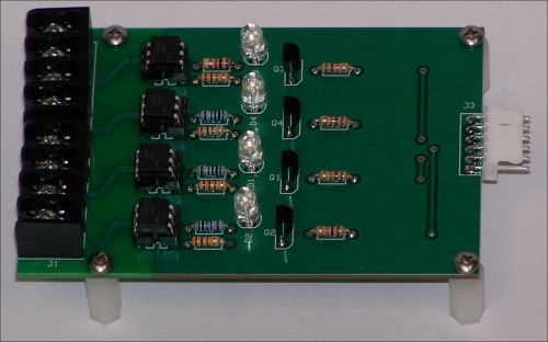
Assembled opto-isolator output PCB
The preceding photograph shows the assembled PCB. Observant readers may notice that the color code of the 1K resistor for the first output is different from the rest. This resistor is what you are probably used to and has the normal 5 percent color code.
Brown, black, red, and gold means (1 - 0) x 100 with a 5 percent tolerance, that is, 1000 ohms.
The other resistors are 1 percent tolerance resistors; so, three decimal places are required.
So, brown, black, black, and brown means, (1 - 0 - 0) x 10 with a 1 percent tolerance, that is, 1000 ohms.
There is no need to use 1 percent resistors in this design. I had them in my lab stock; so, I used them.
You will also note that the white connector hangs over the edge of the board. This is to make it easier to attach the connector when the boards are stacked during the final assembly.
Congratulations! You now have a finished PCB capable of turning 3.3V logic signals into a real world action. Not only can you turn on lights and sirens, you can also use this board to turn on your lawn sprinkler!
The following are two methods of doing just that.
The diagram below shows a small relay connected directly to the output transistor of the opto-isolator. If you want to maintain isolation between the alarm panel and the device you are controlling, the +12V that is powering the relay should have a separate ground return from the panel ground.
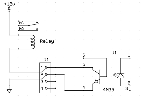
External relay
You can now hook your siren or flashing light to the contacts of the mechanical relay without any fear of blowing the output transistor of the onboard isolator. Accidents happen, and that is why I suggested putting the 4N35s on sockets. They aren't that expensive; so, I suggest you order spares.
In this case, we are using one opto-isolator to drive another opto-isolator. In schematic form, this probably looks a bit odd. However, in the real world, the second isolator can be a high-current device that is capable of switching high voltage and current. In addition to the transistor shown in the drawing, it is also possible to buy opto-isolators with triac outputs for switching AC loads.
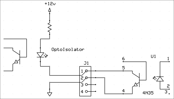
External opto-isolator
An example of one such AC load might be the motor that opens and closes your garage door or the gate at the end of your lane way.
Another application of this type of relay would be to turn on exterior lighting. This could be done either automatically using a zone input and a light sensor or remotely by connecting to the panel via the Internet.
More on remote control later.
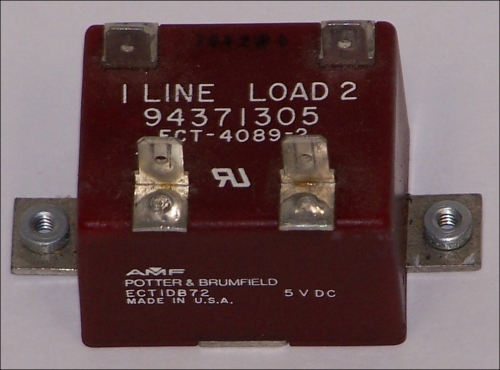
Typical Solid State Relay
The preceding figure shows a high current solid state relay capable of switching AC loads. Note the two mounting fins on either side so that the device can be mounted on a heat sink.
A couple of things that I should mention about SSRs or Solid State Relays is that in this project, the panel will be doubly isolated from the AC load. This is because you have one SSR driving another. Also, SSRs come in various sizes and output configurations, but they all have an LED as the input device. The SSR in the photograph has a TRIAC as an output. This allows you to control AC devices like motors. These relays also come with SCR and power transistor outputs.
Tip
Helpful links
TRIAC: http://en.wikipedia.org/wiki/TRIAC
SCR: http://en.wikipedia.org/wiki/Silicon-controlled_rectifier
You will remember that in Chapter 1, Alarm Systems 101, I said that all alarm systems monitor contacts and perform some actions based on the changes that they see.
One handy use of an AC relay might be to turn on a backup sump pump if the alarm system detects a flood and the primary pump has failed. This would be handy for those of us who live in low-lying areas.
This is where our project comes together and becomes an actual BeagleBone-controlled alarm system. What this board does is connect BeagleBone to the other boards. I have provided you with a third PCB that brings out the I/O pins that the software will use. If you wish, you can build your own using a ProtoBoard such as the one from Circuitco.
The table below shows some of the GPIO pins that are set by default to the GPIO mode without the use of overlays or mux tables.
The pins marked with an * are the ones currently used by the software in this book.
The pins marked with a ~ have been routed for future expansion.
|
P9 |
P8 | ||||||
|---|---|---|---|---|---|---|---|
|
GPIO |
Pin # |
GPIO |
Pin |
GPIO |
Pin # |
GPIO |
Pin |
|
30 |
11 |
60 |
12 ~ |
66 |
7 * |
67 |
8 |
|
31 |
13 |
40 |
14 ~ |
69 |
9 * |
68 |
10 |
|
48 |
15 |
51 |
16 ~ |
45 |
11 * |
44 |
12 |
|
4 |
17 * |
5 |
18 ~ |
23 |
13 * |
26 |
14 |
|
19 |
47 |
15 * |
46 |
16 | |||
|
3 |
21 * |
2 |
22 ~ |
27 |
17 * |
65 |
18 |
|
49 |
23 |
15 |
24 ~ |
22 |
19 * | ||
|
117 |
25 |
14 |
26 ~ | ||||
|
125 |
27 | ||||||
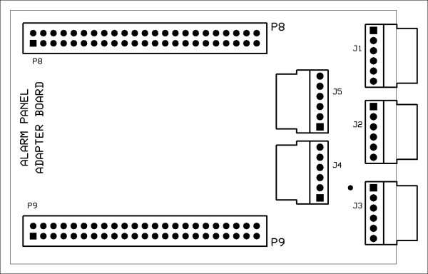
Adapter PCB
The connectors on the Adapter PCB have the following uses in the software that accompanies this book:
- Connector J2 is for "Zones 1 and 2" inputs, connector J3 is for "Zone 3 and 4" inputs, and connector J1 is for "Outputs 1 to 4".
- Pins 12, 14, and 16 have been routed to connector J5, which is labelled as "Zones 5 and 6" on the schematic.
- Pins 18, 22, 24, and 26 have been routed to connector J4, which is labelled as "Outputs 5 to 8" on the schematic.
- You should be aware that these pins can be programmed to be either inputs or outputs. What you use them for is up to you. The BeagleBone +3.3V supply and ground is also connected to these headers, should you require them.
There are two types of 5/8" long nylon spacers in the parts list. One type has a 4-40 screw attached to it. The other type does not.
- Starting with the PCB at the bottom, use the spacers with the 4-40 screw attached to them and fasten this PCB to the PC in the middle, using four more of the same type of spacer.
- You should now have two boards fastened together with the four exposed 4-40 nylon screws.
- Install the other type of 5/8" spacer (without the 4-40 screws attached) on these screws using the spacer as a nut to hold the boards together.
- You can now install the PCB at the top to theses spacers using any type of 4-40 screws that you have at hand, provided that they are no longer than 3/8".
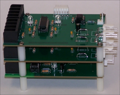
Assembled alarm system PCBs
If you have made it this far and your assembly looks like the preceding photograph, congratulations! You have just finished assembling the PCBs for your alarm system.
You can stack the PCBs in any order you like. I chose to put the zone boards on top and the output board at the bottom.
You will need three harnesses like the one shown in the following figure. I used a red wire to indicate pin 1. This is not strictly necessary because the connectors are keyed.
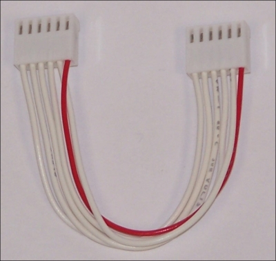
Zone board wiring harness
As far as the wire goes, any 24AWG wire will fit the connector pins. You can even use wires salvaged from an old PC power supply if you like.
The harness is basically a one-to-one connection between the two connectors. While Digikey and others probably sell a hand tool for crimping the connector pins, I found the price too high to justify for just one project. I just used a pair of needle nose pliers to hand crimp the pins. It takes longer and requires a bit of practice, but the price is right and there aren't that many pins to crimp.
The purpose of this harness is to connect the zone and output boards to BeagleBone without the use of the BeagleBone adapter board. What I did was crimp jumper wires into a connector so that I can easily and safely connect the board that I am testing to BeagleBone or the outside world in general.
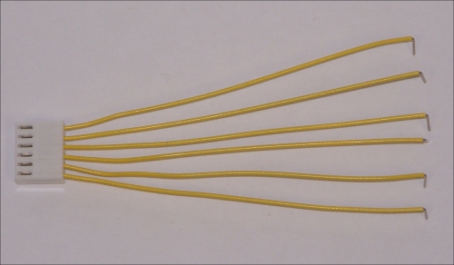
Test harness