
In this chapter we will build the actual alarm system hardware. I have chosen a modular design for the hardware. The hardware consists of three different PCBs or modules; they are as follows.
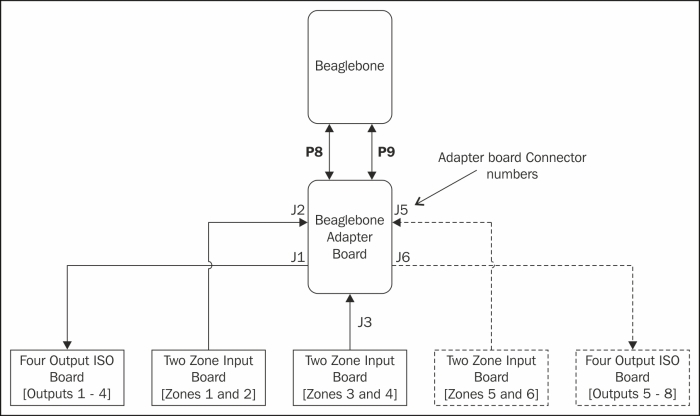
- The first is the module that monitors various zones. In this case, two zones; so, we will be building two identical PCBs in order to monitor four zones. If you want to add zones, just build more zone modules and modify the software (the procedure for doing this was described in Chapter 3, Bigger and Better).The additional modules are shown by dashed lines in the preceding diagram.
- The second module is the optically isolated output board. This is the board that is used to activate lights, sirens, and so on. You can control up to four devices with this board.
- The third board is the one that makes this project a BeagleBone project. What this does is connect the other boards to BeagleBone. If you want to add zones or outputs, this is the part of the hardware that you would modify.
This book uses the original BeagleBone board as the alarm system controller. However, any microcomputer board with input-output capability can be used with this hardware. For example, the RaspberryPi or the Arduino-based systems. For that matter, it is probably possible to use BeagleBoard as well.
Hopefully, this book provides sufficient documentation for an advanced user to adapt the hardware to his or her board.
This is a relatively simple board to assemble. All of the parts used in this project are thru-hole parts; so, no advanced surface mount soldering skills are required. Also, you will find that it is much easier to test and repair.
When I assemble PCBs, I always start with the lowest parts and work towards the highest. This way, when you flip the board on its back, all the parts don't fall out!
Just follow the parts list and silkscreen on the board, and you should not have any problems. Just be sure to double check that the integrated circuits U1 and U2 are installed correctly. The LEDs and diodes are also polarity sensitive. On both devices, the square pad on the PCB is pin 1. The IC will have either a notch milled into it as, shown in the following figure, or a small round indentation that indicates pin 1.
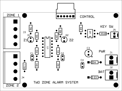
Silkscreen of zone monitor PCB
Connectors J3 and J4 on the zone monitor schematic are your connections to the zones that you wish to monitor. Pins 1 and 2 of each connector are the zone inputs. Pins 3 and 4 are used to supply power to the PIRs and other active sensors. Pin 4, which is called GND or ground, is the +12V return. It is not the same as the COM or common input.
Connector J5 is the key switch input. Applying +12V to pin 2 and grounding pin 1 will turn on the opto-isolator U2. This will pull the /key signal low.
This +12V can come from a key switch, a push button switch, a toggle switch, or anything you like as long as it applies +12V to the opto-isolator.
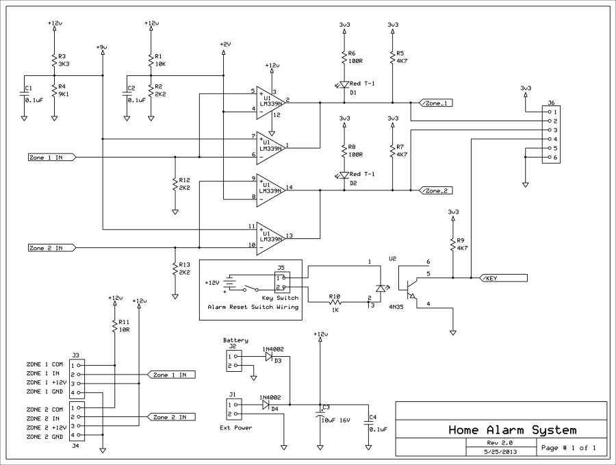
Zone monitor schematic
The following photograph shows the completed PCB.
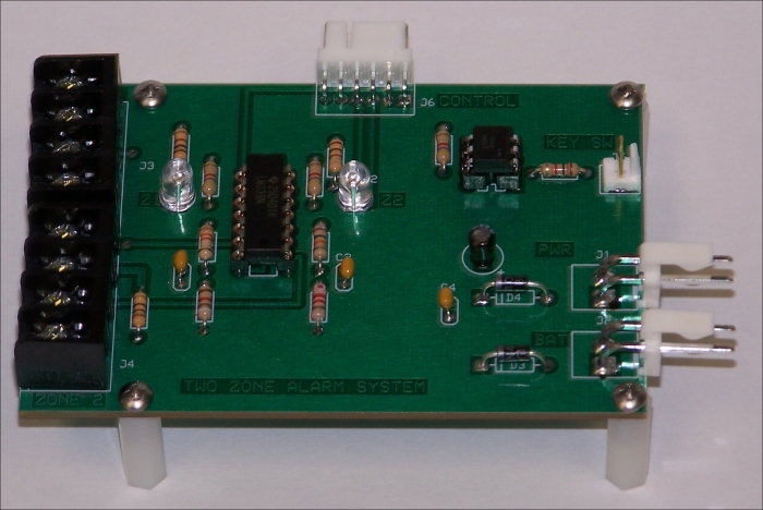
Assembled two zone input PCB
You will notice that I have used sockets for the ICs. This is not strictly necessary, but when I build prototypes, I use sockets until I am sure that the design will work. Also notice that the rectifier diodes D3 and D4 are raised off the board. This is to allow better cooling, should they need it.