
The following series of steps will test the zone board, which the alarm system will use to talk to detect changes in the outside world.
Now that we have completed our visual check of the board and fixed the errors, it is time to apply power to the board.
- Apply 13.5V DC supply to either J1 or J2 of the board.
- Connect the negative lead of the multimeter to pin 2 of either J1 or J2.
- Measure the voltage at the anode (end without the stripe) of D4 or D5, depending on which connector you chose.
- Make a note of this voltage.
- Measure the voltage at the cathode (stripe) end of the diode. The voltage should be about 0.7V less than the voltage on the anode. (This is because there is about a 0.7V across the PN junction of most rectifier diodes.)
- Apply 3.3V (or 3V if you are using batteries) to pins 1 and 6 of J6. Be CAREFUL because there is no polarity protection on this connector. Pin 1 is the positive terminal and pin 6 is the negative or the ground terminal.
- You should measure 3.3V between pin 1 and the ground terminal with the meter.
- If these measurements are correct, you can remove the power for now.
Now that we have completed the power test, it is time to see if the board actually works.
In the following steps, we are simulating a zone that has been connected to the alarm system:
- Connect a 5.6K ohm resistor in series with an SPDT (single pole double throw) switch, and connect this between the COM terminal (1) and the ZONE terminal (2) on the terminal strip. See the following figure; make sure the switch is closed so that the 5.6K ohm resistor is connected across pins 1 and 2.
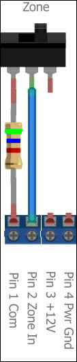
Zone input EOL resistor
- Apply both 13.5V and 3.3V power to the board.
- The LED associated with the zone you are testing should be off.
- Change the switch position so that the connection is now open. This simulates an alarm condition.
- The LED associated with the zone you are testing should turn on.
- Do this test for both the zones.
The following series of steps will test the output board, which the alarm system will use to talk to the outside world.
The following figure shows the test fixture that I built using a common protoboard.
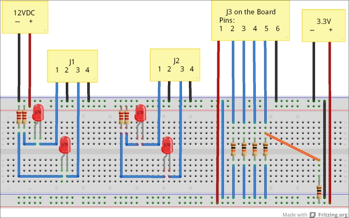
Protoboard test fixture
From left to right, the output of the opto-isolator is connected to an LED. The emitter of the opto-isolator is connected to the ground terminal, while the collector is connected to the cathode of an LED. This LED is in turn connected to +12V through a 2.2K ohm resistor. When the opto-isolator is turned on, current flows from the collector to the emitter and the LED turns on. There are two identical circuits here; one for each output connector.
Connector J3 from the board is connected to 3.3V and four pull-down resistors. There is a 1K ohm resistor that is used to simulate the output of the BeagleBone. By connecting the orange wire to the various inputs, you can simulate a logical 1 on the input and turn on the opto-isolator. You will recall that we built a six-pin test connector in the previous chapter. It is this connector that you should use to connect the board you are testing to the protoboard. You can use any kind of 24AWG solid wire to connect J1 and J2 to the protoboard. SparkFun sells jumper packs for just this purpose.
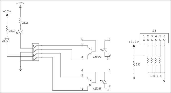
Protoboard schematic
For those of you who prefer schematics, the previous figure shows a schematic representation of the test fixture.
The 10K resistors are pull-downs that hold the input at logic 0. When you connect the 1K resistor to one of the pins of J3, you are applying logic 1 to the input. This simulates the output of the BeagleBone.
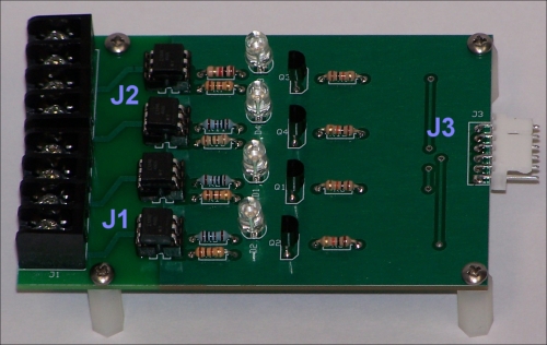
Output board
What we are about to do in the following tests is simulate the BeagleBone outputs without using an actual BeagleBone. In that way, we don't need any special software and there is no risk to our actual BeagleBone. The following steps show how we do it:
- Connect the orange wire from the 1K resistor to the wire leading to pin 2 of J3.
- D1 should light, and the LED connected to pins 1 and 2 of terminal strip J1 should light.
- Connect the orange wire from the 1K resistor to the wire leading to pin 3 of J3.
- D2 should light, and the LED connected to pins 3 and 4 of terminal strip J1 should light.
- Connect the orange wire from the 1K resistor to the wire leading to pin 4 of J3.
- D3 should light, and the LED connected to pins 1 and 2 of terminal strip J2 should light.
- Connect the orange wire from the 1K resistor to the wire leading to pin 5 of J3.
- D4 should light, and the LED connected to pins 3 and 4 of terminal strip J2 should light.