
Now that the basics of the rendering are working, it’s time to revisit game architecture. Even small games (Pong, for example) usually require a large amount of code. Pong is a pretty simple game; the player moves a paddle left or right and attempts to hit a ball past an opponent’s paddle. It was one of the first popular computer games released in 1987 so there have been numerous reimplementations since then. SourceForge (www.sourceforge.net) is a website that hosts hundreds of thousands of open source projects. There are quite a few open source Pong clones, and even the simplest ones are over 1,000 lines of code. As a game programmer, it’s important to have strategies to manage that complexity.
Big games are orders of magnitude more complex than Pong. Kelly Brock revealed that there was a single function over 32,000 lines long in the Sims computer game. This was posted in a discussion on the Software Development for Games mailing list (a great list to join for any aspiring game programmer; you can register to join on this website http://lists.midnightryder.com/listinfo.cgi/sweng-gamedev-midnightryder.com). Games with strict deadlines and lots of pressure can cause the code to become large and unmanageable. Being familiar with some basic architecture techniques can help make code clearer and its function more separated and defined.
The majority of game objects need at least two functions: an update function where the object can handle its animation or anything that changes over time, and a render function where the object can draw itself on screen. This can easily be described in C# using an interface.
public interface IGameObject
{
    void Update(double elapsedTime);
    void Render();
}
Now anything you want to create in the game can inherit from this interface. The I in IGameObject is used to identify the interface as an interface in the code. When designing the game structure, the code can refer to IGameObjects in general without having to worry about the specifics of what any game object actually is. We can start using game objects right away to describe game state.
Games are usually broken up into lots of different states. At the top level there’s perhaps a company splash screen followed by a title menu, there are submenus for options such as sounds, an option to start the game, and perhaps several others. Here’s a naïve way to program that kind of game state.
enum GameState
{
  CompanySplash,
  TitleMenu,
  PlayingGame,
  SettingsMenu,
}

GameState _currentState = GameState.CompanySplash;

public void Update(double elapsedTime)
{
  switch (_currentState)
  {
  case GameState.CompanySplash:
     {
        // Update the starting splash screen
     } break;
  case GameState.SettingsMenu:
    {
       // Update the settings menu
    } break;
  case GameState.PlayingGame:
    {
       // Update the game
    } break;
  case GameState.TitleMenu:
    {
       // Update title menu
    } break;
  default:
    {
       // Error invalid state
    } break;
  }
}
There are a few things to notice here. The code is very long and prone to become complicated and hard to follow. It also breaks the DRY principle. To add a new state, let’s say a credits screen, a new entry must be added to the game state enum and then added to the switch statement. When extending the code, the fewer places that require change the better.
This big switch statement can be replaced with a much better system using the IGameObject interface, where every game state is a game object.
It’s probably best to start a new project with a game loop to follow this example. Once this is done, it’s time to create a new class implementing the IGameObject interface for each game state.
namespace GameStructure
{
    class SplashScreenState : IGameObject
    {
    }
}
Here a splash screen class has been created that inherits from the IGameObject interface. The above code is invalid because it doesn’t implement any of the IGameObject methods. Instead of typing the methods out by hand, one of the refactoring shortcuts can be used to create them automatically. Right-click the IGameObject text and a context menu will appear, as shown in Figure 6.1.
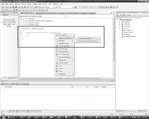
There are two options. Implement Interface Explicitly will do the same as Implement Interface but instead of creating the method Render(), it will create the method IGameObject.Render();, explicitly describing where the method comes from. Here is the code once the refactoring tools have implemented the IGameObject interface.
class SplashScreenState : IGameObject
{
  #region IGameObject Members

  public void Update(double elapsedTime)
  {
     throw new NotImplementedException();
  }
  public void Render()
  {
     throw new NotImplementedException();
  }

  #endregion
}
We’re not implementing the splash screen functionality at the moment; therefore, the exceptions can be removed to make testing the code easier. Something like the following will be easier to work with.
public void Update(double elapsedTime)
{
    System.Console.WriteLine("Updating Splash");
}

public void Render()
{
    System.Console.WriteLine("Rendering Splash");
}
That’s one state—the rest can be created in much the same way. Create a few of the states for practice.
Once the states are made, the code to handle these states is quite simple. To follow the rest of the code, you should create the TitleMenuState. It doesn’t need any functionality. If it just prints out its name in the render and update functions, then that’s great. If you’re still not sure how to create it then you can check the code on the CD.
Here’s an example of how the states might be used in the Form.cs file.
StateSystem _system = new StateSystem();
public Form1()
{
  // Add all the states that will be used.
  _system.AddState("splash", new SplashScreenState(_system));
  _system.AddState("title_menu", new TitleMenuState());
  // Select the start state
  _system.ChangeState("splash");
States are created and added to a state system with a name to identify them. States can then be selected by calling ChangeState and passing in a state name. The state system will manage the update and render of the current active state. Sometimes a state will want to change the active state. For example, a splash screen usually displays an image or animation and then changes state to the title screen. For a splash screen state to change state it must have a reference to the state system.
class SplashScreenState : IGameObject
{
  StateSystem _system;
  public SplashScreenState(StateSystem system)
  {
     _system = system;
  }

  #region IGameObject Members

  public void Update(double elapsedTime)
  {
     // Wait so many seconds then call _system.ChangeState("title_menu")
     System.Console.WriteLine("Updating Splash");
  }

  public void Render()
  {
     System.Console.WriteLine("Rendering Splash");
  }

  #endregion
}
Then when creating the state, the StateSystem can be passed into the constructor.
  _system.AddState("splash", new SplashScreenState(_system));
class StateSystem
{
    Dictionary<string, IGameObject> _stateStore = new Dictionary<string,
IGameObject>();
  IGameObject _currentState = null;
  public void Update(double elapsedTime)
  {
  if (_currentState == null)
  {
     return; // nothing to update
  }
  _currentState.Update(elapsedTime);
  }

  public void Render()
  {
     if (_currentState == null)
  {
     return; // nothing to render
  }
  _currentState.Render();
  }

  public void AddState(string stateId, IGameObject state)
  {
     System.Diagnostics.Debug.Assert( Exists(stateId) == false );
     _stateStore.Add(stateId, state);
  }

  public void ChangeState(string stateId)
  {
     System.Diagnostics.Debug.Assert(Exists(stateId));
     _currentState = _stateStore[stateId];
  }

  public bool Exists(string stateId)
  {
     return _stateStore.ContainsKey(stateId);
  }
}
The StateSystem class is a good class for unit testing—try writing some tests in NUnit. The tests should be short snippets of code that check just one area; here’s an example:
[TestFixture]
public class Test_StateSystem
{
  [Test]
  public void TestAddedStateExists()
  {
    StateSystem stateSystem = new StateSystem();
    stateSystem.AddState("splash", new SplashScreenState
    (stateSystem));

    // Does the added function now exist?
    Assert.IsTrue(stateSystem.Exists("splash"));
  }
The rest of the tests can be found on the CD at CodeChapter 6Chapter6-2 Test_StateSystem.cs. Try to write your own and then compare them with the code on the CD.
Now that the StateSystem has been created, a simple demo can show it in action. We can start with implementing the splash screen state. As we can only draw spinning triangles, it’s not going to be that impressive, but it’s good enough for a demo. Let’s begin by implementing the title splash screen.
class SplashScreenState : IGameObject
{
    StateSystem _system;
    double _delayInSeconds = 3;

  public SplashScreenState(StateSystem system)
  {
    _system = system;
  }

  #region IGameObject Members

  public void Update(double elapsedTime)
  {
    _delayInSeconds -= elapsedTime;
    if (_delayInSeconds <= 0)
  {
    _delayInSeconds = 3;
    _system.ChangeState("title_menu");
  }
  }

  public void Render()
  {
    Gl.glClearColor(1, 1, 1, 1);
    Gl.glClear(Gl.GL_COLOR_BUFFER_BIT);
    Gl.glFinish();
  }

  #endregion
}
This code has the state wait three seconds and then it changes the state to the title menu. The splash screen state will render the screen white while it’s active. We’ll have to cover 2D rendering and sprites before something interesting can be shown.
class TitleMenuState : IGameObject
{
    double _currentRotation = 0;
    #region IGameObject Members

  public void Update(double elapsedTime)
  {

    _currentRotation = 10 * elapsedTime;
  }

  public void Render()
  {
    Gl.glClearColor(0.0f, 0.0f, 0.0f, 1.0f);
    Gl.glClear(Gl.GL_COLOR_BUFFER_BIT);
    Gl.glPointSize(5.0f);

    Gl.glRotated(_currentRotation, 0, 1, 0);
    Gl.glBegin(Gl.GL_TRIANGLE_STRIP);
  {
    Gl.glColor4d(1.0, 0.0, 0.0, 0.5);
    Gl.glVertex3d(-0.5, 0, 0);
    Gl.glColor3d(0.0, 1.0, 0.0);
    Gl.glVertex3d(0.5, 0, 0);
    Gl.glColor3d(0.0, 0.0, 1.0);
    Gl.glVertex3d(0, 0.5, 0);
  }
  Gl.glEnd();
  Gl.glFinish();
  }

  #endregion
}
It’s the spinning triangle from before. These states have already been loaded in to the state system in the earlier examples. The only remaining task is to call the Update and Render functions in the Form.cs.
private void GameLoop(double elapsedTime)
{
  _system.Update(elapsedTime);
  _system.Render();
  _openGLControl.Refresh();
}
That’s it. Run the code now and a white screen will appear for three seconds, followed by a spinning triangle. That proves the state system works quite well and we can now use this to break up the code. Next, it’s time to leave the high-level concepts of architecture and return to the details of rendering.
Up until now the OpenGL scene has not been explicitly setup; the default settings have been used. By setting up the scene manually, much more control is given to how a game appears.
The size of the form is currently rather arbitrary; it’s been left at the default size that Visual Studio made it. Real games need to specify how large their window is going to be. With the current settings, try enabling full-screen mode. The result is shown in Figure 6.2.

The program has successfully gone full-screen, but the triangle is being rendered in the bottom-left corner. This issue arises from there being two different sizes with which to be concerned. One is the size of the form. This is what’s changed when in full-screen mode. The second size is the OpenGL viewport; this hasn’t changed at all, and that’s why it’s still rendering the triangle the same small size.
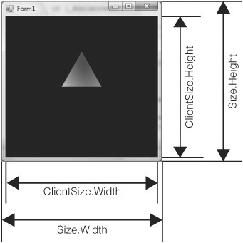
To fix this we must know when the form changes size and inform OpenGL about the change. The form’s size can be accessed in a number of ways. Figure 6.3 shows the difference between the form Size and ClientSize values. Size includes things like the frame and title bar. We’re only interested in the size of the form where the OpenGL graphics are drawn. This can be obtained by querying the ClientSize value of the form.
In the form you’ll see an overridable method call, OnClientSizeChanged; this is the perfect place to update the OpenGL viewport size. In Form.cs, add this method.
protected override void OnClientSizeChanged(EventArgs e)
{
  base.OnClientSizeChanged(e);
  Gl.glViewport(0, 0, this.ClientSize.Width, this.ClientSize.Height);
}
Now any time the client size is changed, such as going to full-screen, the OpenGL viewport will be changed to match it. This also allows the form to be resized at runtime without problem. Check full-screen again and the triangle will be fullsized.
The initial size of the form can be set by setting the ClientSize property.
ClientSize = new Size(800, 600);
This will set the form’s client area to 800 pixels by 600 pixels.
Humans, as you are no doubt aware, have two eyes. The eyes are set in the face horizontally, and this gives us a wider horizontal viewing range than vertical. Widescreen TVs and monitors are more natural for us to use than square or vertically tall ones. The relationship between the width and height of a viewing area is called the aspect ratio. Certain aspect ratios are more comfortable than others. It’s easy in code to provide a range of different aspect ratios.
If the ClientSize is set to 800 by 600, its aspect ratio is 1.33—the width is 1.33 times longer than the height. This ratio is also referred to as 4:3. 4:3 is a minimum; as widescreens become more popular, aspect ratios of 16:9 become more popular. PlayStation 3 has a default resolution of 1280 by 720; the width is 1.73 times greater than the height, and this is commonly referred to as a 16:9 aspect ratio.
if (_fullscreen)
{
  FormBorderStyle = FormBorderStyle.None;
  WindowState = FormWindowState.Maximized;
}
else
{
  ClientSize = new Size(1280, 720);
}
Play around with different aspect ratios to decide what you like. Bear in mind that if you wish to release your game to a large number of people, they may not be able to support resolutions as high as you can. It may be worth trying to support a number of different aspects and resolutions.
When playing around with resolutions, you may observe that in certain resolutions the triangle seems a little squashed or distorted. OpenGL’s viewport is now set correctly, but OpenGL’s default aspect is 1:1, a square. It’s not going to map to 4:3 or 16:9 very gracefully. OpenGL aspect is 1:1 because that is how the aspect is set up by default. In order to change it, the projection matrix must be altered.
Computer monitors and televisions display 2D pictures while OpenGL deals with 3D data. A projection matrix transforms the 3D data to the 2D screen. There are two types of projection matrix that we’re concerned with, orthographic and perspective. Simply, orthographic is used for 2D graphics like hud elements, 2D games, and text. Perspective is used for 3D games like an FPS game.
The orthographic matrix ignores the depth information; it doesn’t matter how far away an item is from the user, it remains the same size. With a perspective projection, things that are farther away are smaller. Those are the main differences.
Even 3D games need to be able to render 2D graphics.
A new function should be made in Form.cs named Setup2DGraphics.
private void Setup2DGraphics(double width, double height)
{
  double halfWidth = width / 2;
  double halfHeight = height / 2;
  Gl.glMatrixMode(Gl.GL_PROJECTION);
  Gl.glLoadIdentity();
  Gl.glOrtho(-halfWidth, halfWidth, -halfHeight, halfHeight, -100, 100);
  Gl.glMatrixMode(Gl.GL_MODELVIEW);
  Gl.glLoadIdentity();
}
This code has a lot of new OpenGL functions, but they’re all straightforward. OpenGL has a number of matrix modes. The value GL_PROJECTION changes the OpenGL state. Once the state is changed, all OpenGL commands will affect the projection matrix. This matrix can now be altered to set up an orthographic projection matrix.
glLoadIdentity clears the current projection information. The next command glOrtho, sets up an orthographic projection matrix. There are six arguments for this function.
void glOrtho(GLdouble left,
   GLdouble right,
   GLdouble bottom,
   GLdouble top,
   GLdouble nearVal,
   GLdouble farVal);
The first four arguments describe how big you want the view of the world to be. Figure 6.4 shows the orthographic projection and how the six arguments affect it. At the moment, the origin is right in the center of the screen. I’ve decided to keep that. To make the origin the top-left corner, you could write the following.
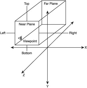
Gl.glOrtho(0, width, -height, 0, -100, 100);
The final two values are the near and far planes. If the z position of a vertex is greater than the far plane, the vertex isn’t rendered. If it’s lower than the near plane, then it also isn’t rendered. Generally, 2D graphics have the z position all set to 0 so the near and far planes don’t really matter. They’re much more important for rendering 3D graphics.
The setup function can be called in the Form.cs constructor.
public Form1()
{
  // Add all the states that will be used.
  _system.AddState("splash", new SplashScreenState(_system));
  _system.AddState("title_menu", new TitleMenuState());

  // Select the start state
  _system.ChangeState("splash");

  InitializeComponent();
  _openGLControl.InitializeContexts();

  if (_fullscreen)
  {
     FormBorderStyle = FormBorderStyle.None;
     WindowState = FormWindowState.Maximized;
  }
  else
  {
     ClientSize = new Size(1280, 720);
  }
  Setup2DGraphics(ClientSize.Width, ClientSize.Height);
  _fastLoop = new FastLoop(GameLoop);
}
The projection matrix will need re-creating anytime the form changes size. Therefore, a call to Setup2DGraphics should also be added to the OnClientSizeChanged callback.
protected override void OnClientSizeChanged(EventArgs e)
{
  base.OnClientSizeChanged(e);
  Gl.glViewport(0, 0, this.ClientSize.Width, this.ClientSize.Height);
  Setup2DGraphics(ClientSize.Width, ClientSize.Height);
}
The title state renders a triangle, but the triangle’s maximum width is only 1 OpenGL unit. The previous projection matrix had a width and height of 2 so the triangle appeared a good size. The width and height of this new projection matrix is 1280 and 720 so the triangle barely takes up a pixel and therefore cannot be seen!
An easy way to fix this is to make the triangle bigger. Find the triangle drawing code and make the width and height 50 instead of 1.
Gl.glColor4d(1.0, 0.0, 0.0, 0.5);
Gl.glVertex3d(-50, 0, 0);
Gl.glColor3d(0.0, 1.0, 0.0);
Gl.glVertex3d(50, 0, 0);
Gl.glColor3d(0.0, 0.0, 1.0);
Gl.glVertex3d(0, 50, 0);
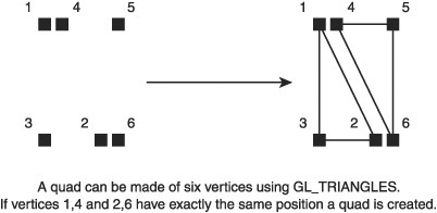
This will make the triangle visible once again. Most 2D graphics use two triangles to make a quad. This quad then has a texture applied to it and forms the basis of a 2D game or heads-up display.
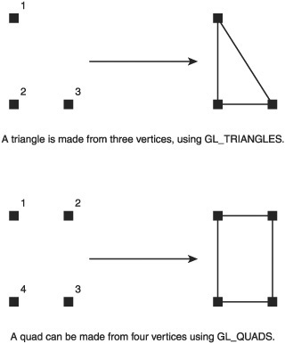
The first step of creating a sprite is to create a quad. A triangle is made of three vertices; a quad is made of four. See Figure 6.5. A sprite is a pretty basic game element, and it’s a good idea to make it into its own class. There will also be a class responsible for drawing the sprites. This class will be called the Renderer. Before implementing the Renderer and Sprite classes, it’s useful to first consider how they will be used. Here is some pseudo code of how sprites might be used.
Renderer renderer = new Renderer();
Sprite spaceship = new Sprite();
spaceship.SetPosition(0, 0);
spaceship.SetTexture(_textureManager.Get("spaceship"));
renderer.DrawSprite(spaceship);
A quad is made from four vertices, but it’s common practice to use six vertices and draw two triangles to make up the quad. Graphics cards work very well with triangles, so many engines have all their assets broken up into triangles or triangle strips. The quad is broken up as shown in Figure 6.6.
Coding as you read helps you understand the material. There’s no need to start a new project; the GameStructure project can be reused. Create a new class that inherits from IGameObject, called DrawSpriteState.
class DrawSpriteState : IGameObject
{
  #region IGameObject Members

  public void Update(double elapsedTime)
  {
  }

  public void Render()
  {
  }

  #endregion
}
Remember to include the statement using Tao.OpenGl; at the top of the file so OpenGL commands can be used. This game state will be used to test the sprite drawing code. It needs to be the state that’s loaded as soon as the program starts; modify the code in Form.cs as follows.
public Form1()
{
  // Add all the states that will be used.
  _system.AddState("splash", new SplashScreenState(_system));
  _system.AddState("title_menu", new TitleMenuState());
  _system.AddState("sprite_test", new DrawSpriteState());

  // Select the start state
  _system.ChangeState("sprite_test");
This will load the currently empty sprite drawing state. Running the code will display a blank window. A quad is made from two triangles arranged to form a square shape. OpenGL draws triangles clockwise.
public void Render()
{
  Gl.glClearColor(0.0f, 0.0f, 0.0f, 1.0f);
  Gl.glClear(Gl.GL_COLOR_BUFFER_BIT);
  Gl.glBegin(Gl.GL_TRIANGLES);
  {
     Gl.glVertex3d(-100, 100, 0); // top left
     Gl.glVertex3d(100, 100, 0); // top right
     Gl.glVertex3d(-100, -100, 0); // bottom left
  }
  Gl.glEnd();
}
This code will draw the top half of the quad. Running the code will produce an image similar to Figure 6.7.
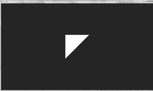
Drawing the second half is easy. In clockwise order, the top-right vertex needs to be drawn, then the bottom right, and finally the bottom left. The code to do this should be written just after the first half of the quad.
Gl.glVertex3d( 100, 100, 0); // top right
Gl.glVertex3d( 100, -100, 0); // bottom right
Gl.glVertex3d(-100, -100, 0); // bottom left
These two triangles make a full square. Not all game sprites will be perfect squares. Therefore, it’s important to be able to specify the width and height. The current quad is 200 by 200. OpenGL doesn’t have explicit dimensions; the 200 can be whatever unit you like—feet, meters, etc. The screen has been set up so that 200 OpenGL units map up to 200 pixels, but that isn’t always guaranteed. Currently the width, height, and position of the sprite are all hard coded. These magic numbers need to be replaced with variables.
double height = 200;
double width = 200;
double halfHeight = height / 2;
double halfWidth = width / 2;

Gl.glBegin(Gl.GL_TRIANGLES);
{
  Gl.glVertex3d(-halfWidth, halfHeight, 0); // top left
  Gl.glVertex3d( halfWidth, halfHeight, 0); // top right
  Gl.glVertex3d(-halfWidth, -halfHeight, 0); // bottom left

  Gl.glVertex3d( halfWidth, halfHeight, 0); // top right
  Gl.glVertex3d( halfWidth, -halfHeight, 0); // bottom right
  Gl.glVertex3d(-halfWidth, -halfHeight, 0); // bottom left
}
The values are exactly the same as before, but now the height and width are stored as variables following the DRY principle. The height and width can now be altered easily to form any number of interestingly shaped rectangles.
The sprite’s size is now easy to modify, but there’s no way to modify the position. Changing the position is what will be added next.
double x = 0;
double y = 0;
double z = 0;
Gl.glBegin(Gl.GL_TRIANGLES);
{
  Gl.glVertex3d( x - halfWidth, y + halfHeight, z); // top left
  Gl.glVertex3d( x + halfWidth, y + halfHeight, z); // top right
  Gl.glVertex3d( x - halfWidth, y - halfHeight, z); // bottom left

  Gl.glVertex3d(x + halfWidth, y + halfHeight, z); // top right
  Gl.glVertex3d(x + halfWidth, y - halfHeight, z); // bottom right
  Gl.glVertex3d(x - halfWidth, y - halfHeight, z); // bottom left
}
Gl.glEnd();
This is equivalent to the previous code, but now the x, y, and z positions can be altered. The position represents the center of the quad. Try changing the x, y, and z values and move the quad about.
Textures are very easy to apply to the quad we have. The tricky part of textures is loading them from the hard disk into memory. A texture class needs to be created to represent the textures in memory, as well as a TextureManager class to store the textures. Internally, OpenGL references textures by an integer id; the texture struct will just store that id and the width and height of the texture.
public struct Texture
{
  public int Id { get; set; }
  public int Width { get; set; }
  public int Height { get; set; }

  public Texture(int id, int width, int height) : this()
  {
     Id = id;
     Width = width;
     Height = height;
  }
}
The texture class is quite straightforward. Its constructor calls the this constructor because it’s a struct type and needs to have the members initialized for the autogenerated assessor methods to use.
Next, the TextureManager loads the texture data from the disk and associates it with an id provided by OpenGL. The texture is also associated with a human readable name so that it’s easy to work with. The code to load the texture requires an additional reference, Tao.DevIl, to be added to the project. Add it the same way you added Tao.OpenGL. DevIl is short for Developer’s Image Library. It can load most image formats so that OpenGL can use them.
The DevIL library also requires a number of DLL files to run; these must be in the same directory as your binary file. This directory will probably be bindebug. Find the Tao Framework directory; it will most likely be in your C:Program File (x86) (or the C:Program Files directory on Windows XP). Navigate to TaoFrameworklib and copy DevIl.dll, ILU.dll, and ILUT.dll into your bin debug directory. When you do a release build, you will need to copy all relevant dlls to bin
elease, too. Once this is done you can start using DevIl.
The DevIl library has to be initialized and told to work with OpenGL. Form.cs is a good place to initialize DevIl. Make sure you add the using statement, as shown below, to the top of the Form.cs file.
using Tao.DevIl;
Then in the form’s constructor, add the following code.
// Init DevIl
Il.ilInit();
Ilu.iluInit();
Ilut.ilutInit();
Ilut.ilutRenderer(Ilut.ILUT_OPENGL);
Create a new class called TextureManger. At the top, add the using statements for DevIl and OpenGL.
Here’s the basic TextureManager code
class TextureManager : IDisposable
{
  Dictionary<string, Texture> _textureDatabase = new Dictionary<string,
Texture>();

  public Texture Get(string textureId)
  {
     return _textureDatabase[textureId];
  }
  #region IDisposable Members

  public void Dispose()
  {
     foreach (Texture t in _textureDatabase.Values)
     {
        Gl.glDeleteTextures(1, new int[] { t.Id });
     }
  }

  #endregion
}
The class implements IDisposable; it ensures that if the class is destroyed, it will release the textures from memory. The only other function is Get; this takes a name of a texture and returns the associated texture data. If the data doesn’t exist, it will throw an exception.
The TextureManager class has one obvious omission: there is no function to load the texture from the hard disk.
public void LoadTexture(string textureId, string path)
{
  int devilId = 0;
  Il.ilGenImages(1, out devilId);
  Il.ilBindImage(devilId); // set as the active texture.

  if (!Il.ilLoadImage(path))
  {
      System.Diagnostics.Debug.Assert(false,
        "Could not open file, [" + path + "].");
  }
  // The files we'll be using need to be flipped before passing to OpenGL
  Ilu.iluFlipImage();
  int width = Il.ilGetInteger(Il.IL_IMAGE_WIDTH);
  int height = Il.ilGetInteger(Il.IL_IMAGE_HEIGHT);
  int openGLId  = Ilut.ilutGLBindTexImage();

  System.Diagnostics.Debug.Assert(openGLId != 0);
  Il.ilDeleteImages(1, ref devilId);

  _textureDatabase.Add(textureId, new Texture(openGLId, width,
height));
}
The DevIL library was written to complement OpenGL so it has a very similar interface. An image is generated and then bound. Binding an image means all subsequent operations will affect that image. ilLoadImage is called, which loads the texture data into memory. iluFlipImage is called on the image, and this flips it on the Y axis; most of the common image formats need to be flipped to work correctly with OpenGL. The image is then queried for width and height information. Finally, the DevIl utility library is used to bind the texture to an OpenGL id. The id, width, and height are all wrapped in the texture class, which is then returned. DevIl still has the texture data in memory; this is freed using ilDeleteImages, as the data has now been moved from DevIl to OpenGL.
Testing the TextureManager requires a texture. A TIF image file, called face. tif, can be found on the CD in the Asset directory. Copy it into your project directory. Then in Visual Studio, right-click the project and choose Add > Existing Item. We’re going to add the TIF file to the project. This brings up a dialog box. To see the image you will probably have to change the filter from C# Files to All Files. Select face.tif. The final step is to select the face.tif file in the solution explorer, right-click, and select Properties, as shown in Figure 6.8.
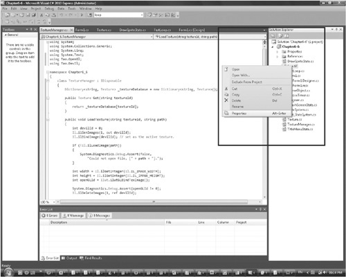
A number of fields are displayed describing the properties of the image file. Change the field Copy To Output Directory to Copy If Newer. This will copy the image file over to the bin directory, and once you run the program, the file will always be in the correct place. Adding the image file to the project isn’t necessary, but it’s a simple way to keep track of the assets and to make sure they are put in the right places.
The TextureManager object can be created in the Form.cs file and then passed into any state that requires it.
TextureManager _textureManager = new TextureManager();

public Form1()
{
  InitializeComponent();
  _openGLControl.InitializeContexts();

  // Init DevIl
  Il.ilInit();
  Ilu.iluInit();
  Ilut.ilutInit();
Ilut.ilutRenderer(Ilut.ILUT_OPENGL);

// Load textures
_textureManager.LoadTexture("face", "face.tif");

// Add all the states that will be used.
_system.AddState("splash", new SplashScreenState(_system));
_system.AddState("title_menu", new TitleMenuState());
_system.AddState("sprite_test", new DrawSpriteState());

// Select the start state
_system.ChangeState("sprite_test");
This setup code in the Form.cs creates the TextureManager, initializes the DevIL library, and then attempts to load a texture called face.tif. Run the program. If it works, that’s great; you can now load textures from the disk. If it fails to run then there are a couple of things that may have gone wrong.
If you get an exception of the form Unable to load DLL 'xx.dll': The specified module could not be found, then xx.dll is not being found by your binary file. It should be in the bindebug directory. Check if it’s there. If it’s not there then look in the Tao framework and copy it across.
If you get the exception BadImageFormatException, this has nothing to do with the texture you’re trying to load. Instead, it’s having trouble loading the DevIl libraries. The most likely reason for this is that you are developing with Visual Studio 2008 on a 64-bit system, but the libraries have been compiled for 32 bit. The easiest way to fix this is to go to the solution explorer. Right-click the project and select Properties. Click the Build tab on the left, as shown in Figure 6.9.
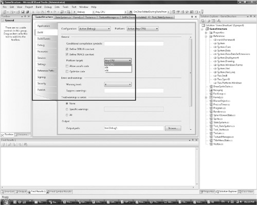
There is a drop-down box next to Platform Target. Choose x86; this will make the program build for 32-bit systems.
Finally, if you get an Assertion Failed message with the text Could not open file, [face.tif], then face.tif is not in the binary directory; either copy the file into the correct location or make sure you added it to the solution correctly.
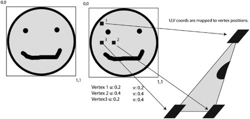
Once textures are being loaded, it’s time to start using them. Texture maps are indexed from 0 to 1 on both axes. 0,0 is the top-left corner and 1,1 is the bottom right. For textures, the axes aren’t called X and Y; instead, they’re called U and V.
Figure 6.10 shows how the 2D U,V coordinates for each vertex are mapped on to the 3D vertex positions. It will be easier to play with the U,V mapping once texturing is working with the quad example.
Return to the DrawSpriteState class. A constructor that takes in a TextureManager needs to be created.
class DrawSpriteState : IGameObject
{
  TextureManager _textureManager;

  public DrawSpriteState(TextureManager textureManager)
{
    _textureManager = textureManager;
}
In Form.cs, that TextureManager will now need to be passed in to the Draw-SpriteState constructor. The textures are easily accessible in the game state.
To use the texture, OpenGL needs to be told to start the texture mode, then the texture is bound as the active texture. All vertices will use the currently bound texture for their texture information. Finally, each vertex needs to have some 2D texture positions associated with it. Here it’s just mapping from 0,0 to 1,1 so the full texture is used.
This code sets the texture information for the first triangle of the quad. The result can be seen in Figure 6.11.

Texture texture = _textureManager.Get("face");
Gl.glEnable(Gl.GL_TEXTURE_2D);
Gl.glBindTexture(Gl.GL_TEXTURE_2D, texture.Id);

Gl.glBegin(Gl.GL_TRIANGLES);
{
  Gl.glTexCoord2d(0, 0);
  Gl.glVertex3d( x - halfWidth, y + halfHeight, z); // top left
  Gl.glTexCoord2d(1, 0);
  Gl.glVertex3d( x + halfWidth, y + halfHeight, z); // top right
  Gl.glTexCoord2d(0, 1);
  Gl.glVertex3d( x - halfWidth, y - halfHeight, z); // bottom left
The second triangle’s vertices are set in the same way.
Gl.glTexCoord2d(1, 0);
Gl.glVertex3d(x + halfWidth, y + halfHeight, z); // top right
Gl.glTexCoord2d(1, 1);
Gl.glVertex3d(x + halfWidth, y - halfHeight, z); // bottom right
Gl.glTexCoord2d(0, 1);
Gl.glVertex3d(x - halfWidth, y - halfHeight, z); // bottom left
This will now map the texture to a quad entirely. Try changing the size of the quad to see what happens.
The texture has been applied using a lot of magic numbers and these should be moved to variables according to the DRY principle. The U,V mapping for the quad can be described by two coordinates, the top-left U,V positions and the bottom-right U,V positions.
float topUV = 0;
float bottomUV = 1;
float leftUV = 0;
float rightUV = 1;

Gl.glBegin(Gl.GL_TRIANGLES);
{
  Gl.glTexCoord2d(leftUV, topUV);
  Gl.glVertex3d( x - halfWidth, y + halfHeight, z); // top left
  Gl.glTexCoord2d(rightUV, topUV);
  Gl.glVertex3d( x + halfWidth, y + halfHeight, z); // top right
  Gl.glTexCoord2d(leftUV, bottomUV);
  Gl.glVertex3d( x - halfWidth, y - halfHeight, z); // bottom left

  Gl.glTexCoord2d(rightUV, topUV);
  Gl.glVertex3d(x + halfWidth, y + halfHeight, z); // top right
  Gl.glTexCoord2d(rightUV, bottomUV);
  Gl.glVertex3d(x + halfWidth, y - halfHeight, z); // bottom right
  Gl.glTexCoord2d(leftUV, bottomUV);
  Gl.glVertex3d(x - halfWidth, y - halfHeight, z); // bottom left
}
Gl.glEnd();
It is now easy to change around the UV coordinates. Set the top left to 0,0 and the bottom right to 2,2. Then change the bottom right to –1, –1. Play around with different position for the top-left and bottom-right coordinates to see what happens.
It is very common to want to make part of a sprite transparent. There is a second sprite called face_alpha.tif available on the CD in the Assets folder. This image file has four channels, red, green, blue, and alpha. The alpha channel removes the white border around the smiley face. The face_alpha file should be added to the project in the same way as the previous texture. It then needs to be loaded into the TextureManager.
// Load textures
_textureManager.LoadTexture("face", "face.tif");
_textureManager.LoadTexture("face_alpha", "face_alpha.tif");
In the Render call of DrawSpriteState, change the line
Texture texture = _textureManager.Get("face");
to
Texture texture = _textureManager.Get("face_alpha");
Running the code now will produce exactly the same image as before. This is because OpenGL hasn’t been told to deal with transparency yet. Transparency in OpenGL is achieved by blending. OpenGL blends the pixels that have already been drawn to the frame buffer with whatever pixels are about to be drawn to the frame buffer.
Gl.glEnable(Gl.GL_TEXTURE_2D);
Gl.glBindTexture(Gl.GL_TEXTURE_2D, texture.Id);
Gl.glEnable(Gl.GL_BLEND);
Gl.glBlendFunc(Gl.GL_SRC_ALPHA, Gl.GL_ONE_MINUS_SRC_ALPHA);
Blending needs to first be enabled. This can be done just underneath where the 2D texture mode was enabled. Then the blend function must be set. The blend function takes two arguments. The first argument modifies the value of the pixel to be drawn onto the frame buffer, and the second argument modifies the value of the frame buffer pixel that will be drawn over. The incoming pixel to be drawn onto the frame buffer is known also known as the “source”. GL_SRC_ALPHA is an instruction to use the alpha of the incoming pixel. GL_ONE_MINUS_SRC_ALPHA is an instruction to take the alpha of the incoming pixel from one. These two instructions blend the incoming pixel onto the frame buffer using its alpha value. The glBlendFunc modifies the R,G,B values of the source and frame buffer pixels, after which the sum of these values is written to the frame buffer.
In all the examples given so far, the initial color of the frame buffer is black. Every pixel is of the RGBA form 0,0,0,1. The smiley face being rendered has lots of different types of pixels. The pixels in the corner areas are white but with an alpha of zero. The RGBA values are generally 1,1,1,0.
When the pixels in the corner areas of the smiley face texture are rendered, they will have an alpha value of zero. The value of one minus the source alpha is (1 – 0), so, 1. The new frame buffer colors are calculated by multiplying the incoming pixels by the source alpha and then multiplying the current frame pixels by one minus the source alpha and then adding the two results together.
incomingRed * 0 + frameBufferRed * 1
incomingGreen * 0 + frameBufferGreen * 1
incomingBlue * 0 + frameBufferBlue * 1
As you can see, using this blend the incoming pixels are ignored, making the corners of the face appear transparent. The general equation is
(incomingRGB * incomingAlpha) + (framebufferRGB * (1 – incomingAlpha)) Try working through this as if the incoming alpha was 1 or 0.5. This is how OpenGL performs its blending.
Running the program will produce a face with the white backing removed.
The current sprite code is quite comprehensive. It’s easy to set the sprite texture, U, V mapping, position, width, and height. The final operation that is quite common with sprites is to alter the color. In many games, text can change color and images may flash yellow to attract the attention of the user. This is normally done through color modulation.
The basics of this technique have already been covered when the spinning triangle was created. Each vertex is given a color. It’s easier if the sprite has one single color and then all vertices share it.
The color only needs to be set once, and then all the vertices will be set that color.
float red = 1;
float green = 0;
float blue = 0;
float alpha = 1;

Gl.glBegin(Gl.GL_TRIANGLES);
{
  Gl.glColor4f(red, green, blue, alpha);
This code will turn the sprite red. Altering the alpha will affect the entire sprite’s transparency. Using this code, it’s very easy to imagine how to fade something in by changing the alpha from 0 to 1 over time.
In certain cases it may be desirable to give a sprite a gradient rather than a solid color. This can be achieved by setting the bottom vertices one color and the top vertices a second color. The color will be interpolated by OpenGL and will create a gradient automatically.
The basics of a sprite have been demonstrated, but it’s all quite untidy at the moment, and very hard to reuse. All the code needs to be wrapped up into classes. The color, position, and U,V point data all need to be separated into their own classes. It would be ideal to use pre-existing C# classes for these data structures, but it’s better to make our own as they will need to be tailored to work correctly with OpenGL.
The sprite class will contain the sprite data, but a separate renderer class will be responsible for rendering the sprites. Separating the functionality in this way allows the rendering code to be optimized later.
Here are the three structures.
[StructLayout(LayoutKind.Sequential)]
public struct Vector
{
  public double X { get; set; }
  public double Y { get; set; }
  public double Z { get; set; }

  public Vector(double x, double y, double z) : this()
  {
     X = x;
     Y = y;
     Z = z;
  }

}

[StructLayout(LayoutKind.Sequential)]
public struct Point
{
  public float X { get; set; }
  public float Y { get; set; }

  public Point(float x, float y)
  : this()
  {
  X = x;
  Y = y;
  }
}

[StructLayout(LayoutKind.Sequential)]
public struct Color
{
  public float Red { get; set; }
  public float Green { get; set; }
  public float Blue { get; set; }

  public float Alpha { get; set; }

  public Color(float r, float g, float b, float a)
     : this()
  {
     Red = r;
     Green = g;
     Blue = b;
     Alpha = a;
  }
}
Vectors are a common tool in game programming. Conceptually they are different than positions in 3D space, but they have the same X,Y,Z values. Generally vectors are used to represent positions as this makes the code simpler. The vector here doesn’t have any methods; it will be fleshed out when we investigate what vectors are used for, later on.
The vector structure, and all the other structure, have metadata attached [StructLayout(LayoutKind.Sequential)]. This requires an additional using statement.
using System.Runtime.InteropServices;
This metadata informs the complier that it should layout the structures in memory the same as the C programming language would. This makes it easier to interact with OpenGL, which is written in C.
The Point structure will be used to describe the U,V coordinates. Double precision isn’t need for the texture coordinates so a floating number is used instead. The Color is used to describe the colors of the vertices.
Here is the renderer class.
using Tao.OpenGl;
using System.Runtime.InteropServices;

namespace GameStructure
{
  public class Renderer
  {
     public Renderer()
     {
        Gl.glEnable(Gl.GL_TEXTURE_2D);
        Gl.glEnable(Gl.GL_BLEND);
        Gl.glBlendFunc(Gl.GL_SRC_ALPHA, Gl.GL_ONE_MINUS_SRC_ALPHA);
     }

     public void DrawImmediateModeVertex(Vector position, Color color,
Point uvs)
     {
        Gl.glColor4f(color.Red, color.Green, color.Blue, color.Alpha);
        Gl.glTexCoord2f(uvs.X, uvs.Y);
        Gl.glVertex3d(position.X, position.Y, position.Z);
     }

     public void DrawSprite(Sprite sprite)
     {
        Gl.glBegin(Gl.GL_TRIANGLES);
     {
        for (int i = 0; i <Sprite.VertexAmount; i++)
        {
            Gl.glBindTexture(Gl.GL_TEXTURE_2D, sprite.Texture.Id);
            DrawImmediateModeVertex(
               sprite.VertexPositions[i],
               sprite.VertexColors[i],
               sprite.VertexUVs[i]);
        }
     }
     Gl.glEnd();
    }
  }
}
In the constructor, the Renderer sets up the relevant texture and blend modes. These operations are now done once on start up rather than every frame as before. The DrawSprite function is responsible for taking a sprite and rendering it. All the OpenGL calls are the same as before; there is one to set the texture and then one for the color, texture, U,Vs, and position.
This leaves the sprite class itself. A lot of the functions can be inferred from its use in the renderer. Games generally have a lot of sprites so it’s important to make the class as lightweight as possible and only include the most essential members.
public class Sprite
{
  internal const int VertexAmount = 6;
  Vector[] _vertexPositions = new Vector[VertexAmount];
  Color[] _vertexColors = new Color[VertexAmount];
  Point[] _vertexUVs = new Point[VertexAmount];
  Texture _texture = new Texture();

  public Sprite()
  {
     InitVertexPositions(new Vector(0,0,0), 1, 1);
     SetColor(new Color(1,1,1,1));
     SetUVs(new Point(0, 0), new Point(1, 1));
  }

  public Texture Texture
  {
     get { return _texture; }
     set
     {
       _texture = value;
       // By default the width and height is set
       // to that of the texture
       InitVertexPositions(GetCenter(), _texture.Width, _texture.
Height);
     }
  }

  public Vector[] VertexPositions
  {
     get { return _vertexPositions; }
  }

  public Color[] VertexColors
  {
     get { return _vertexColors; }
  }
  public Point[] VertexUVs
  {
  get { return _vertexUVs; }
  }
  private Vector GetCenter()
  {
    double halfWidth = GetWidth() / 2;
    double halfHeight = GetHeight() / 2;

  return new Vector(
    _vertexPositions[0].X + halfWidth,
    _vertexPositions[0].Y - halfHeight,
    _vertexPositions[0].Z);
  }

  private void InitVertexPositions(Vector position, double width, double
height)
  {
    double halfWidth = width / 2;
    double halfHeight = height / 2;
    // Clockwise creation of two triangles to make a quad.

    // TopLeft, TopRight, BottomLeft
    _vertexPositions[0] = new Vector(position.X - halfWidth, position.Y +
halfHeight, position.Z);
    _vertexPositions[1]= new Vector(position.X + halfWidth, position.Y +
halfHeight, position.Z);
    _vertexPositions[2]= new Vector(position.X - halfWidth, position.Y -
halfHeight, position.Z);

    // TopRight, BottomRight, BottomLeft
    _vertexPositions[3]= new Vector(position.X + halfWidth, position.Y +
halfHeight, position.Z);
    _vertexPositions[4]= new Vector(position.X + halfWidth, position.Y -
halfHeight, position.Z);
    _vertexPositions[5]= new Vector(position.X - halfWidth, position.Y -
halfHeight, position.Z);
  }

  public double GetWidth()
  {
    // topright - topleft
    return _vertexPositions[1].X - _vertexPositions[0].X;
  }
public double GetHeight()
{
  // topleft - bottomleft
  return _vertexPositions[0].Y - _vertexPositions[2].Y;
}

public void SetWidth(float width)
{
  InitVertexPositions(GetCenter(), width, GetHeight());
}

public void SetHeight(float height)
{
  InitVertexPositions(GetCenter(), GetWidth(), height);
}

public void SetPosition(double x, double y)
{
SetPosition(new Vector(x, y, 0));
}

public void SetPosition(Vector position)
{
  InitVertexPositions(position, GetWidth(), GetHeight());
}

public void SetColor(Color color)
{
  for (int i = 0; i < Sprite.VertexAmount; i++)
{
  _vertexColors[i] = color;
}
}

public void SetUVs(Point topLeft, Point bottomRight)
{
  // TopLeft, TopRight, BottomLeft
  _vertexUVs[0] = topLeft;
  _vertexUVs[1]= new Point(bottomRight.X, topLeft.Y);
  _vertexUVs[2]= new Point(topLeft.X, bottomRight.Y);

  // TopRight, BottomRight, BottomLeft
    _vertexUVs[3]= new Point(bottomRight.X, topLeft.Y);
    _vertexUVs[4]= bottomRight;
    _vertexUVs[5]= new Point(topLeft.X, bottomRight.Y);

  }
}
The sprite class is quite large, mainly due to accessor functions and some overloaded functions. The sprite has a default constructor; it creates a sprite of size 1 by 1 with an empty texture. Once a texture is set, the width and height of the sprite is automatically set to the texture values. Once the sprite is created, the position, dimension, textures, and U,Vs can all be changed as needed.
With sprite code packaged into a class, it’s now time to demonstrate how to use it. Create a new game state called TestSpriteClassState, load it into the state system, and make it the default state to run when the program executes. TestSpriteClassState will need to take the TextureManager in to its constructor like the DrawSpriteState did.
Renderer _renderer = new Renderer();
TextureManager _textureManager;
Sprite _testSprite = new Sprite();
Sprite _testSprite2 = new Sprite();

public TestSpriteClassState(TextureManager textureManager)
{
  _textureManager = textureManager;
  _testSprite.Texture = _textureManager.Get("face_alpha");
  _testSprite.SetHeight(256*0.5f);

  _testSprite2.Texture = _textureManager.Get("face_alpha");
  _testSprite2.SetPosition(-256, -256);
  _testSprite2.SetColor(new Color(1, 0, 0, 1));

}
public void Render()
{
  Gl.glClearColor(0.0f, 0.0f, 0.0f, 1.0f);
  Gl.glClear(Gl.GL_COLOR_BUFFER_BIT);
  _renderer.DrawSprite(_testSprite);
  _renderer.DrawSprite(_testSprite2);
  Gl.glFinish();
}
This state renders two different sprites: one is squashed; the other is offset from the center of the screen and colored red. The code is very straightforward and easy to use. All the heavy lifting has been done in the Sprite and Renderer classes. These classes are only written once but used everywhere, so it’s worth making them as friendly and easy to use as possible.
It’s very easy to animate these sprites by changing the U,Vs or changing the texture as time passes. The positions can also be easily changed with time. This should be done in the update loop. Feel free to dive in right now and see what you can make. If you’re a little unsure where to start, then keep reading and the concepts will become apparent as you’re guided through the creation of a game.