
Games can be written without a lot of advanced math knowledge, but the more graphically advanced the game, the more math you’ll need to know. There are many fields of mathematics; some are more commonly used than others when writing a game. Geometry is important to describe 3D and 2D worlds. Matrices and vectors are useful for describing worlds and the relationships between entities in these worlds. Trigonometric functions are great for special effects and making things act organically. Tween functions are a handy way to express movement over a constant time. The more math you know, the more tools you have to solve any problems that come up when programming games.
The trigonometric functions sine and cosine are often used in game programming. Applying sine and cosine to some number will return a value from −1 to 1. These returned values make up a wave form, a smoothly oscillating curve. This curve is of great use when moving something up and down smoothly—creating an organic pulsing color, smooth oscillating scaling, and many other game-like effects.
The best way to get a feel for the uses of cosine and sine is to create a sandbox program where you can play with the values. A good starting point is a program that plots the sine and cosine waves on a graph. Here’s a game state that will draw some axis and plot a particular graph. You don’t need to create a new project. You can just add this state to your existing code and then set it as the default state.
class WaveformGraphState : IGameObject
{
  double _xPosition = -100;
  double _yPosition = -100;
  double _xLength = 200;
  double _yLength = 200;
  double _sampleSize = 100;
  double _frequency = 2;
  public delegate double WaveFunction(double value);

  public WaveformGraphState()
  {
    Gl.glLineWidth(3);
    Gl.glDisable(Gl.GL_TEXTURE_2D);
  }

  public void DrawAxis()
  {
    Gl.glColor3f(1, 1, 1);

    Gl.glBegin(Gl.GL_LINES);
    {
     // X axis
     Gl.glVertex2d(_xPosition, _yPosition);
     Gl.glVertex2d(_xPosition + _xLength, _yPosition);
     // Y axis
     Gl.glVertex2d(_xPosition, _yPosition);
     Gl.glVertex2d(_xPosition, _yPosition + _yLength);
    }
    Gl.glEnd();
  }

  public void DrawGraph(WaveFunction waveFunction, Color color)
  {
    double xIncrement = _xLength / _sampleSize;
    double previousX = _xPosition;
    double previousY = _yPosition + (0.5 * _yLength);
    Gl.glColor3f(color.Red, color.Green, color.Blue);
    Gl.glBegin(Gl.GL_LINES);
    {
     for (int i = 0; i < _sampleSize; i ++)
     {

       // Work out new X and Y positions
       double newX = previousX + xIncrement; // Increment one unit on the x
       // From 0-1 how far through plotting the graph are we?
       double percentDone = (i / _sampleSize);
       double percentRadians = percentDone * (Math.PI * _frequency);

       // Scale the wave value by the half the length
       double newY = _yPosition + waveFunction(percentRadians) *
(_yLength / 2);

       // Ignore the first value because the previous X and Y
       // haven't been worked out yet.
       if (i > 1)
       {
        Gl.glVertex2d(previousX, previousY);
        Gl.glVertex2d(newX, newY);
       }

       // Store the previous position
       previousX = newX;
       previousY = newY;
     }
    }
    Gl.glEnd();
  } // Empty Update and Render methods omitted
}
The member variables _xPosition, _yPosition, _xLength, and _yLength are used to position and describe the size of the graph. The smoothness of the graph is determined by the _sampleSize variable. The sample size is the number of vertices used to draw the line of the graph. Each vertex y position is determined by a particular wave function such as sine or cosine. The _frequency variable is used to determine how often the wave will oscillate, the higher the frequency the greater the number of oscillations.
The default values describe a graph positioned at x:-100, y:-100 with each axis being 200 pixels long. This will make the graph big enough to easily read, but the DrawGraph function treats the graph as if the x and y axes run from 0 to 1.
After the member variables, a delegate is defined.
public delegate double WaveFunction(double value);
Graphs are often defined as x = x0, y = f(x0) where x0 is the next value of x and plain x is the previous value. The x value is usually increased by a set number and the y value is calculated from the x. The WaveFunction delegate describes f in the formula; a function that takes in some double value and returns some double value. This is the same signature of the cosine and sine functions. By using a WaveFunction type, the DrawGraph function can take in cosine, sine, or any other wave function and no extra code needs to be written.
The state’s constructor sets the line width to 3 pixels making the graph lines easy to see. It also turns off the texture state; if the texture state is turned on, the lines may appear dull because they are incorrectly being assigned an invalid texture.
The DrawGraph function is the most important function in the game state. It is responsible for plotting the graph. It uses the sample rate to work out how to space the vertices so that any line will totally fill the length graph. There are two common ways to define angles: degrees and radians. Degrees are quite commonly known; a full circle is 360°, and a half circle is 180°. Radians are a measurement of degrees using Pi, a full circle is two times Pi, and a half circle is Pi. The C# Sin and Cos functions expect to be given an angle in radians; for this reason, the 0-1 value of the X axis is scaled by Pi when the Y axis values are being calculated.
The inner loop of the DrawGraph function works out a new position from the old position and then plots a line from the old position to the new position. To demonstrate the code in action, a Render function needs to be written that calls DrawGraph for sine and cosine. The graph output can be seen in Figure 8.1.
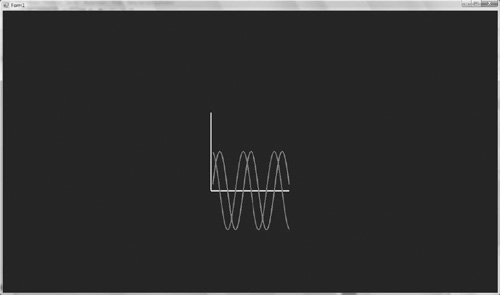
public void Render()
{
  DrawAxis();
  DrawGraph(Math.Sin, new Color(1,0,0,1));
  DrawGraph(Math.Cos, new Color(0, 0.5f, 0.5f, 1));
}
The DrawGraph function takes in a function used to plot the graph and a color that decides what color the graph will be. Sine and cosine are waveforms, and it’s easy to make interesting new wave forms by adding these waves together. A new waveform function can be created by using an anonymous method. This code snippet creates a graph that combines cosine and sine but scales the result down by a half.
DrawGraph(delegate(double value)
{
  return (Math.Sin(value) + Math.Cos(value)) *0.5;
}, new Color(0.5f, 0.5f, 1, 1));
Try the following snippet and observe the graph you get.
DrawGraph(delegate(double value)
{
  return (Math.Sin(value) + Math.Sin(value + value))*0.5;
}, new Color(0.5f, 0.5f, 1, 1));
These graphs look interesting, but without a game application, they may seem academic and rather dull. Next, these functions will be used to animate sprites.
Create a new game state called SpecialEffectsState. This state will demonstrate how to use the sine and cosine functions that have just been covered to create cool special effects with the text class.
class SpecialEffectState : IGameObject
{
  Font _font;
  Text _text;
  Renderer _renderer = new Renderer();
  double _totalTime = 0;

  public SpecialEffectState(TextureManager manager)
  {
    _font = new Font(manager.Get("font"), FontParser.Parse("font.fnt"));
    _text = new Text("Hello", _font);
  }

  public void Update(double elapsedTime)
  {
  }

  public void Render()
  {
    Gl.glClearColor(0.0f, 0.0f, 0.0f, 1.0f);
    Gl.glClear(Gl.GL_COLOR_BUFFER_BIT);
    _renderer.DrawText(_text);
    _renderer.Render();
  }
}
The basic state just renders out the text “Hello.” It’s very easy to use the sine value to make this text pulse the opacity from 0–1 and back again. Text is used here, but it could just as easily be a sprite or model.
public void Update(double elapsedTime)
{
  double frequency = 7;
  float _wavyNumber = (float)Math.Sin(_totalTime*frequency);
  _wavyNumber = 0.5f + _wavyNumber * 0.5f; // scale to 0-1
  _text.SetColor(new Color(1, 0, 0, _wavyNumber));

  _totalTime += elapsedTime;
}
The total time keeps track of how long the state has been running. The number keeps increasing and will eventually become so big that it wraps around to 0. It’s used to feed the sine function numbers that will produce a wave similar to the one plotted previously. The sine wave is scaled so that it oscillates between 0 and 1 rather than – 1 and 1. The frequency is increased as well to make the pulse occur more often. Run the code and check out the effect.
After pulsing in and out of sight, the next step is to have the text travel through a garish rainbow of all the colors. Each color channel is assigned a different sine or cosine wave and the strengths of each channel change over time.
public void Update(double elapsedTime)
{
  double frequency = 7;
  float _wavyNumberR = (float)Math.Sin(_totalTime*frequency);
  float _wavyNumberG = (float)Math.Cos(_totalTime*frequency);
  float _wavyNumberB = (float)Math.Sin(_totalTime+0.25*frequency);
  _wavyNumberR = 0.5f + _wavyNumberR * 0.5f; // scale to 0-1
  _wavyNumberG = 0.5f + _wavyNumberG * 0.5f; // scale to 0-1
  _wavyNumberB = 0.5f + _wavyNumberB * 0.5f; // scale to 0-1

  _text.SetColor(new Color(_wavyNumberR, _wavyNumberG,
_wavyNumberB, 1));

  _totalTime += elapsedTime;
}
It’s very easy to play with this code to get a wide variety of different effects. The color channel isn’t the only thing that can by modified using trigonometric functions; the next example will alter the position of the text. To change the text position a SetPosition method must be added to the Text class. To move the text, every vertex that makes up every character must have its position changed; the easiest way to do this is just to re-create all these characters at the new position.
public void SetPosition(double x, double y)
{
  CreateText(x, y);
}
With the Text classes SetPosition method defined, it can be used in the Update loop to create a new text-based special effect.
public void Update(double elapsedTime)
{
  double frequency = 7;
  double _wavyNumberX = Math.Sin(_totalTime*frequency)*15;
  double _wavyNumberY = Math.Cos(_totalTime*frequency)*15;

  _text.SetPosition(_wavyNumberX, _wavyNumberY);

  _totalTime += elapsedTime;
}
This will move the text in a rough circle. This time the numbers don’t need to be scaled between 0 and 1; instead, they are increased so the movement of the text is very obvious. Different functions can be used to alter the position of the text as needed.
Finally, this last example takes each letter of the text and animates it as if a wave was passing along the word. To animate each individual character of the text, a new GetPosition method must be added to the Sprite class. The sprite position is taken from the center of the sprite.
public Vector GetPosition()
{
  return GetCenter();
}
With the above code added to the Sprite class, the new GetPosition method can be used in the Update loop.
public void Update(double elapsedTime)
{
  double frequency = 7;

  int xAdvance = 0;
  foreach (CharacterSprite cs in _text.CharacterSprites)
  {
    Vector position = cs.Sprite.GetPosition();
    position.Y= 0 + Math.Sin((_totalTime + xAdvance) * frequency)*25;
    cs.Sprite.SetPosition(position);
    xAdvance++;
  }

  _totalTime += elapsedTime;
}
Vectors are a very common game programming tool. The easiest way to get a good feel for vector math is to use it in a game. Very quickly the possible uses will become second nature. A simple vector class has already been made in the previous chapters, but until now none of its properties have been defined.
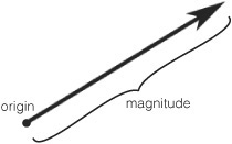
In game programming, vectors are used to manipulate and describe 3D game worlds. Mathematically, vectors are described as a direction with a magnitude. The magnitude is just the length of the vector. See Figure 8.2.
The most common vectors in game programming are 2D, 3D, and 4D. Four-dimension vectors are used when using projection matrices to translate vertices from 3D to 2D. On paper, vectors and positions are very similar. A position [0, 3, 0] and a vector [0, 3, 0] have the same internal values, but they represent different things. The position uses a coordinate system to define an absolute position in the world. A vector describes a direction (up in this case) and a magnitude or length (in this case, 3). See Figure 8.3 for a comparison. For example, “three miles in the air” is not a position; it’s a description of a position using a direction and a length—a vector.
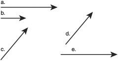
In Figure 8.3, vectors a and e are the same vector because they have the same direction and magnitude. They are at different origins so they appear different places on the diagram. Vectors c and d are also the same. Vector b is the same direction as a and e, but the magnitude is less so it is a different vector.
Vectors, in game programming, are used to answer questions such as:
The enemy spaceship is at position [0, 0, 90]; the player spaceship is at [0, 80, –50]. What direction should the enemy launch a missile? Each frame, how is that missile’s position updated to send it towards the player?
Is the player’s distance from the bomb a meter or less?
Which side of the wall is the player?
Is the player looking at the NPC?
Given a quad that represents the end of a gun, which direction are the bullets going to fire?
How should light reflect off this surface?
Move the car three meters forward.
A player has just hit an enemy; which direction should that enemy move?
How do I increase the force of this bullet by 100?
Which player is nearest the alien artifact?
To be able to answer these questions, the vector class will need to be expanded to add the basic vector methods. The examples in this chapter will build upon the code you have written in previous chapters. Most examples will require you to create a new game state and make this the activate state to test the code. All the example code is available on the CD in the CodeChapter 8 directory. The next sections will explain the various vector operations and list the code that needs to be added to complete the vector class. Game engines sometimes have a Vector2d, Vector3d, and Vector4d, but I think it’s simpler in this case to just have one vector structure; it can still be used for any 2D operations, and for the contents of this book, 4D vectors won’t be used.
[StructLayout(LayoutKind.Sequential)]
public struct Vector
{
  public double X { get; set; }
  public double Y { get; set; }
  public double Z { get; set; }
  public Vector(double x, double y, double z) : this()
  {
    X = x;
    Y = y;
    Z = z;
  }
}
The length operation takes a vector and returns that vector’s magnitude. With a simple vector of [0, 1, 0], it’s easy to see the length is 1, but with a vector of [1.6, –0.99, 8], the length is less apparent. Here is the formula to give a vector’s length.
The two bars around the v are the mathematical notation for the length of a vector. The equation is the same for any dimension of vector: square the members, add them together, and take the square root.
This formula is simple to translate into code. It is broken into two functions: one function will square and add the members; the other will perform the square root.
public double Length()
{
  return Math.Sqrt(LengthSquared());
}
public double LengthSquared()
{
  return (X * X + Y * Y + Z * Z);
}
If you want to compare the length of two vectors the LengthSquared operation can be compared instead of the Length, saving a square root operation and making it slightly more efficient.
Vectors are considered equal if all the members’ values, X,Y, and Z, are equal. Vectors don’t have a position; they are just a direction from some origin. Figure 8.3 has a number of vectors; even though some vectors are placed at different positions, they are still equal because all their members are equal. Three miles north is still three miles north if it’s three miles north of your house, or three miles north of the Great Pyramid of Giza.
It is simple to create an Equals function for the vector.
public bool Equals(Vector v)
{
  return (X == v.X) && (Y == v.Y ) && (Z == v.Z);
}
In code it would be convenient if the == operator was also overloaded. At the moment, the following cannot be written
// Cannot write this
if (vector1 == vector2)
{
  System.Console.WriteLine("They're the same")
}

// Instead must write
if (vector1.Equals(vector2))
{
  System.Console.WriteLine("They're the same")
}
To use the == operator, it needs to be overloaded and that requires a few more functions to be overridden as well, GetHashCode, !=, and Equals (Object obj).
public override int GetHashCode()
{
  return (int)X ^ (int)Y ^ (int)Z;
}

public static bool operator ==(Vector v1, Vector v2)
{
  // If they're the same object or both null, return true.
  if (System.Object.ReferenceEquals(v1, v2))
  {
    return true;
  }

  // If one is null, but not both, return false.
  if (v1 == null || v2 == null)
  {
    return false;
  }

  return v1.Equals(v2);
}

public override bool Equals(object obj)
{
  if (obj is Vector)
  {
    return Equals((Vector)obj);
  }
  return base.Equals(obj);
}

public static bool operator !=(Vector v1, Vector v2)
{
  return !v1.Equals(v2);
}
A lot of code just to overload the equality operator! The only curious function is GetHashCode. A hash is a number that tries, but is not guaranteed, to uniquely identify an object; it’s used in C# Dictionary structures. It needs to be overridden when overriding equality because if equality is overridden, it makes it harder for the compiler to know what a good hash would be.
The vector addition operation is very simple; each member of the first vector is added to the respective member of the second vector. Here is the code to perform vector addition.
public Vector Add(Vector r)
{
  return new Vector(X + r.X, Y + r.Y, Z + r.Z);
}

public static Vector operator+(Vector v1, Vector v2)
{
  return v1.Add(v2);
}
When the binary addition operator + is overloaded, it automatically overloads +=. The same is true for *= and /=.
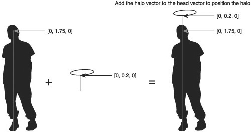
Figure 8.4 shows the result of adding two vectors together. Vectors are often added together when trying to get a certain offset in 3D space. For instance, say you wanted to put a 3D model of a halo above a player’s head. The player origin is directly in between the feet of the character. You have a vector that represents an offset from the player’s feet to the center of the player’s head [0, 1.75, 0].
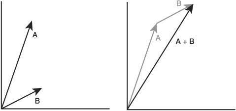
If you add a vector [0, 0.2, 0] that should get you a position that’s perfect for a hovering halo. This operation is shown in Figure 8.5.
Vector subtraction is used all the time to get the vector between two points in space. The calculation is very similar to addition, but the members are subtracted rather than added.
public Vector Subtract(Vector r)
{
  return new Vector(X - r.X, Y - r.Y, Z - r.Z);
}
public static Vector operator-(Vector v1, Vector v2)
{
  return v1.Subtract(v2);
}
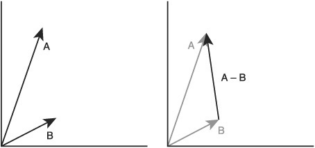
The result of subtracting two vectors is shown in Figure 8.6. In a space battle, one spaceship might want to shoot another spaceship. Spaceship A can subtract its position, represented as a vector, from spaceship B’s position; this will give a vector from A to B (see Figure 8.7). This vector’s direction can be used to aim missiles or advance one craft towards the other.

Vector multiplication is when a vector is multiplied by a scalar number; a scalar number is a number like an int or double, just a normal number. If all a vector’s elements are multiplied against another element, this is known as the dot product and is covered here.
public Vector Multiply(double v)
{
  return new Vector(X * v, Y * v, Z * v);
}

public static Vector operator * (Vector v, double s)
{
  return v.Multiply(s);
}
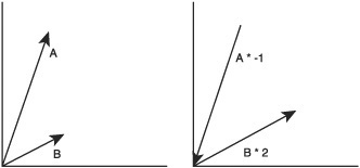
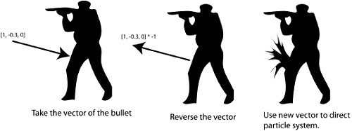
Figure 8.8 shows what occurs when a vector is multiplied by a scalar. Multiplying by a vector scales the vector, so multiplying by 2 will double the length of the vector. Multiplying by –1 will make the vector point in the opposite direction it currently points. If a player character was shot in a 3D game, the vector the bullet was traveling can be multiplied by –1, reversing it. This vector will now point outwards from the body along the line of the bullet’s entry, a perfect vector to use to play a blood splat effect (see Figure 8.9).
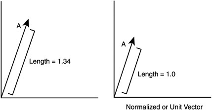
A normal vector is a vector that has a length of exactly 1. These vectors are also known as unit vectors. Unit vectors are an excellent way to represent a direction without caring about the magnitude. The normalize operation maintains the vector’s direction but makes its magnitude equal 1. If a unit vector is multiplied by a scalar, the resulting vector length will be the same as the scalar value. If you have a vector of some unknown length and you want it to be length 6, you can normalize the vector and then multiply by 6.
public Vector Normalize(Vector v)
{
  double r = v.Length();
  if (r != 0.0)       // guard against divide by zero
  {
    return new Vector(v.X / r, v.Y / r, v.Z / r); // normalize and return
  }
  else
  {
    return new Vector(0, 0, 0);
  }
}
This code is not technically correct; it should be impossible to normalize a zero vector, but the code simply does nothing if a zero vector is normalized. Vectors are normalized by calculating their length and then dividing each element by that length. The effect of normalizing a vector can be seen in Figure 8.10.
In game programming, direction is often very important and normal vectors are used to define directions. You may have heard the term normal mapping. This is a texture where each pixel represents a normal vector, the texture is stretched over a 3D model, and the lighting calculations take into account the normal vector on each pixel of the rendered model. Normal mapping gives the surface of the final model a lot more detail than it would otherwise have.
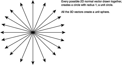
Imagine a two-dimensional vector with an X and Y element. Up, down, left, and right vectors can be created with [0, 1], [0, -1], [1, 0], and [1, 0]. This creates a cross-like shape. If you now created four more normal vectors between these up, down, left, and right vectors you would start to approximate a circle. This is the unit circle; it has a radius of 1. The unit circle can be seen in Figure 8.11. If a three-element vector [X, Y, Z] is used, then a unit sphere is created. If you had all vectors of length 2, then you would have a sphere with a radius of 2 and so on.
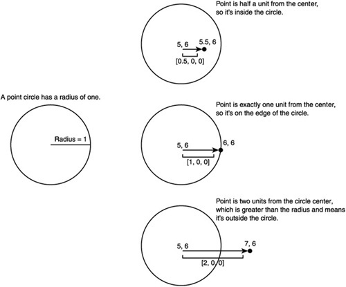
It is very easy to do a circle-point or sphere-point intersection test. This is a test that checks if a point is inside a certain circle or sphere. Let’s take the circle example. A circle is defined by the circle position and a radius. If a unit circle exists at [5, 6] and there is a point [5.5, 6.5] the first step is to get the distance from the circle origin. This is done by vector subtraction of the circle origin from the point [5, 6] – [5.5, 6.5] = [0.5, 0.5] giving the vector from the point to the center of the circle. The distance between the point and the circle is then calculated by performing the length operation on that vector. This gives a length of 0.707.... If this length is smaller than the circle radius, then the point is inside the circle; if it is greater, it is outside. If it is the same, it’s on the very edge of the circle, as Figure 8.12 shows.
The same method works for sphere-point intersection. This is a quick way to see if the player is in a certain position or if the mouse has been used to click on a certain area. If you don’t feel comfortable with it, try sketching out a few examples on a piece of paper until you do. Once you’ve got it, try to think how you might do a circle-circle intersection or a sphere-sphere intersection.
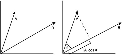
The dot product is an operation that takes two vectors and returns a number. The number returned is related to the angle between the two vectors.
A • B = |A||B|cos(θ)
The dot product operation used on vector A and B returns the length of A and B multiplied by the cosine of the angle between the vectors. This is shown graphically in Figure 8.13. If vectors B and A are normalized, then their length values are 1 and the equation is simplified to A • B = cos(θ). To retrieve the angle, the arccosine operation can be used. In C#, the arccosine function is Math.acos and it returns the angle in radians.
The dot product operation is very good for determining if objects in the game are facing each other. It’s also very useful for testing if an object is on one side of a plane or the other; this is used in 3D games to ensure the character doesn’t walk through walls.
The operation itself is very simple: all the elements from the first vector are multiplied by the second vector, then all these values are added together to produce a scalar. The dot product is a very common operation in 3D graphics, so common the multiply operator * is often overloaded to represent it.
public double DotProduct(Vector v)
{
  return (v.X * X) + (Y * v.Y) + (Z * v.Z);
}

public static double operator *(Vector v1, Vector v2)
{
  return v1.DotProduct(v2);
}
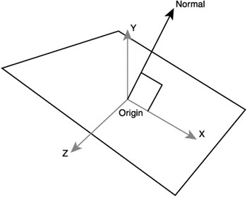
Dot products are great for determining if a point is behind or in front of a plane. A plane is a two-dimensional surface, like a piece of paper. A piece of paper can be positioned and angled anywhere just like a geometric plane. The difference is that a piece of paper has an edge. Planes don’t have edges; they keep going infinitely along their two dimensions—a piece of paper without end! A plane is defined using a point and a normalized vector. (See Figure 8.14.) The point positions the plane in space and the normal specifies the direction it’s pointing.
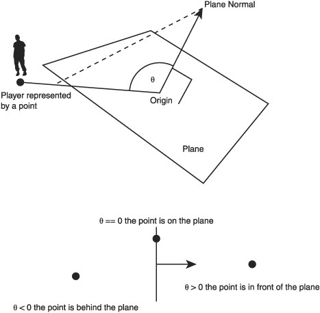
In a game a 3D plane might be positioned somewhere to signify a change; if the player crosses this plane then he has finished the level, or a boss should spawn, or he has fallen to drown in the sea. The test to see which side a player is on goes like this.
Create a vector from the plane position to the player position.
Dot product the plane normal with the newly created vector.
If the result is zero, the player position is exactly on the plane.
If the result is above zero, the player is on the normal side of the plane.
If the result is below zero, the player is on the other side of the plane.
This test can be seen graphically in Figure 8.15.
Dot product tests are used in back face culling. This is a technique to see if some polygon is facing away from the camera. By default, polygons are not double-sided; they only have one side indicated by the normal. If the polygons face away from the camera, they can’t be seen. This means the graphics hardware doesn’t need to be told about them. The dot product can be used to filter out all the polygons that are facing away from the camera.
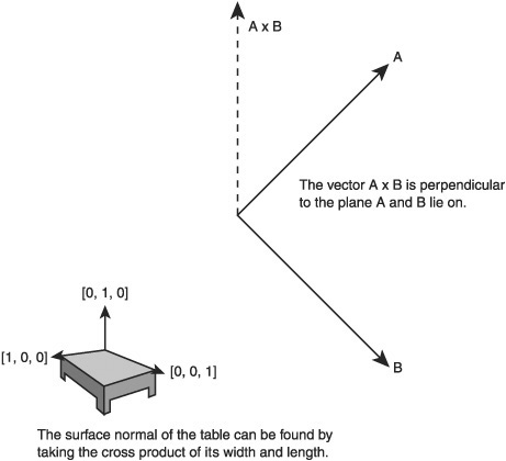
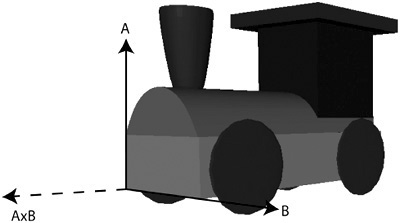
The last vector operation to be covered is the cross-product. Unlike the previous operations, this operation only works on vectors with three or more elements. This means there is no cross-product operation for a simple X,Y vector. The calculation is more complicated than previous operations but the results are quite intuitive. The cross-product takes two vectors and returns a vector perpendicular to the passed in vectors. If you have a table with one side from [0, 0, 0] to [0, 0, 1] and another side from [0, 0, 0] to [1, 0, 0], then the resulting dot product vector will be a vector that is pointing upwards from the table’s surface [0, 1, 0]. The operation can be seen in Figure 8.16.
Here is the formula for calculating the cross-product.
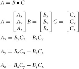
The formula looks rather intimidating; fortunately, once it’s converted to code it can pretty much be ignored. When this formula is used, you won’t be thinking about the particular mechanics of the code, just that you want a vector that points outwards from two cross-product vectors.
public Vector CrossProduct(Vector v)
{
  double nx = Y * v.Z - Z * v.Y;
  double ny = Z * v.X - X * v.Z;
  double nz = X * v.Y - Y * v.X;
  return new Vector(nx, ny, nz);
}
The cross-product is very useful for working out the normal of a surface. For instance, you may have a train that you want to move forward in the 3D world. The train could be at any angle, so it’s hard to know what forward means. First, you really need a normal vector that faces the same way as the train. If you found a polygon on the train facing the way you want, the cross-product of two sides of this polygon will give you a vector that is facing outward from it along the train, as shown in Figure 8.17. This vector can be normalized so it is just a direction. This direction multiplied by some scalar can be added to the train’s position and it will move forward that scalar amount.
By now, quite an impressive, fully functional vector structure has been made, but there are a few final touches that will make it easier to work with. First, the ToString method can be overridden so it outputs something useful. The ToString method is automatically called when using the debugger in Visual Studio. Overriding this method will allow a vector to be understood at a glance, without needing to dig down into the definition and look at the individual values.
public override string ToString()
{
  return string.Format("X:{0}, Y:{1}, Z:{2}", X, Y, Z);
}
The zero vector is a special type of vector; it has no unit vector. It is a vector that represents no direction and has no magnitude. It is a little like the null of vectors. For that reason it is useful to have as a constant.
[StructLayout(LayoutKind.Sequential)]
public struct Vector
{

  public static Vector Zero = new Vector(0, 0, 0);
That is all the vector operations needed. With this simple structure a whole 3D world can be built and manipulated. Don’t worry if you don’t quite understand every little bit at the moment; the more you use the bits you do know the more the rest will fall into place.
Intersection is a way of determining when two shapes overlap or intersect. This is essential in all graphical programming including games. Detecting if the mouse cursor is over a button is an intersection test. In games, detecting if a missile has hit a ship is also an intersection test. 2D intersection is very simple and a great place to start.
Circles are defined with a position and a radius. Intersection is best shown graphically, so let’s create a new game state called CircleIntersectionState and make it load by default.
class CircleIntersectionState : IGameObject
{
  public CircleIntersectionState()
  {
    Gl.glLineWidth(3);
    Gl.glDisable(Gl.GL_TEXTURE_2D);
  }
  #region IGameObject Members

  public void Update(double elapsedTime)
  {
  }

  public void Render()
  {
  }
  #endregion
}
The state currently does nothing apart from getting OpenGL ready to draw lines. Next, a circle class needs to be created.
public class Circle
{
  Vector Position { get; set; }
  double Radius { get; set; }

  public Circle()
  {
    Position = Vector.Zero;
    Radius = 1;
  }

  public Circle(Vector position, double radius)
  {
    Position = position;
    Radius = radius;
  }

  public void Draw()
  {
    // Determines how round the circle will appear.
    int vertexAmount = 10;
    double twoPI = 2.0 * Math.PI;

    // A line loop connects all the vertices with lines
    // The last vertex is connected to the first vertex
    // to make a loop.
    Gl.glBegin(Gl.GL_LINE_LOOP);
    {
     for (int i = 0; i <= vertexAmount; i++)
     {
       double xPos = Position.X + Radius * Math.Cos(i * twoPI /
vertexAmount);
       double yPos = Position.Y + Radius * Math.Sin(i * twoPI /
vertexAmount);
       Gl.glVertex2d(xPos, yPos);
     }
    }
    Gl.glEnd();
  }
}
By default, a circle is defined to be at the origin and to have a radius of 1 unit. The drawing code is currently missing. The circle will be drawn using OpenGL immediate mode—just the outline will be drawn. The sine and cosine functions are used to determine where to plot each vertex that will make up the circle’s perimeter.
To test the drawing function in the CircleIntersectionState, add a _circle member to the class.
Circle _circle = new Circle(Vector.Zero, 200);
This creates a circle of radius 200 around the origin. To see the circle, the render method needs to be modified.
public void Render()
{
  _circle.Draw();
}
Run the program and you should see something similar to Figure 8.18.
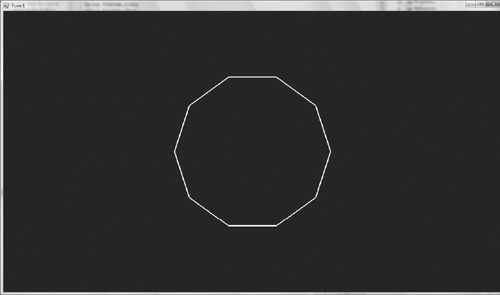
The circle is made from only 10 vertices so it doesn’t appear very smooth. To increase the smoothness increase the number of vertices used in the Draw method of the Circle class.
For the purposes of demonstrating intersection, it would be nice to able to color the circles. A white circle could be a non-intersected circle and a red circle could indicate that it intersects with something. This is an easy addition to make. In the Circle class, modify the code so it has a color member that is used in the Draw function.
Color _color = new Color(1, 1, 1, 1);
public Color Color
{
  get { return _color; }
  set { _color = value; }
}

public void Draw()
{
  Gl.glColor3f(_color.Red, _color.Green, _color.Blue);
By default, all circles will be rendered white but the color can be changed at any time.
Circle-point intersection was covered in the vector section. The distance of the point from the circle origin is calculated; if that distance is greater than the circle radius, then it lies outside of the circle. To test this graphically, the mouse pointer can be used as the point.
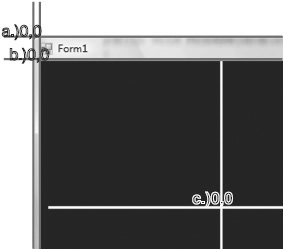
Getting the position of the mouse pointer is a little tricky because of the different coordinate systems involved. The OpenGL origin is in the middle of the form but the cursor’s position is not in the same coordinate system; its origin is the very top left of the form. This means OpenGL considers the position 0, 0 to be a point in the middle of the form while the cursor considers 0,0 to be the very top left of the form. These different coordinate systems are shown in Figure 8.19. The form coordinate origin is labeled a, the control coordinate is labeled b, and the OpenGL coordinate origin is labeled c. To convert the mouse pointer from the form coordinate system to the OpenGL coordinate system a little more code needs to be added to the form.
The first thing we need is a simple Input class to record the mouse input.
public class Input
{
  public Point MousePosition { get; set; }
}
The Input class will be initiated and updated in the form. GameStates that wish to know about the mouse position need to take the Input object into their constructors. Add an Input object to the form class now.
public partial class Form1 : Form
{
  Input _input = new Input();
In the form a new function needs to be created that will update the Input class; this will be called every frame.
private void UpdateInput()
{
  System.Drawing.Point mousePos = Cursor.Position;
  mousePos = _openGLControl.PointToClient(mousePos);

  // Now use our point definition,
  Point adjustedMousePoint = new Point();
  adjustedMousePoint.X = (float)mousePos.X - ((float)ClientSize.Width
/ 2);
  adjustedMousePoint.Y = ((float)ClientSize.Height / 2)-(float)mouse-
Pos.Y;
  _input.MousePosition = adjustedMousePoint;
}

private void GameLoop(double elapsedTime)
{
  UpdateInput();
UpdateInput translates the mouse position from the form’s coordinate system to the control coordinate system by using the PointToClient function. The mouse position is then finally converted to the OpenGL coordinate system based on the center of the OpenGL control. This is done by taking away half the width and height of the control from its X and Y position. The final coordinate now correctly maps the mouse position from the form coordinates to OpenGL coordinates. If the mouse was placed in the center of the OpenGL control, it would have the Input class report the position (0,0).
There is one last thing that needs to be written before leaving the form code. The new input object must be added to the constructor of the circle state.
_system.AddState("circle_state", new CircleIntersectionState(_input));
The state’s constructor must also be modified.
Input _input;
public CircleIntersectionState(Input input)
{
  _input = input;
Once the input is being passed to the state then the mouse position can be used. It’s worth confirming that everything is working correctly. The easiest way to do this is to draw a dot where the cursor is in OpenGL.
public void Render()
{
  Gl.glClearColor(0.0f, 0.0f, 0.0f, 1.0f);
  Gl.glClear(Gl.GL_COLOR_BUFFER_BIT);
  _circle.Draw();

  // Draw the mouse cursor as a point
  Gl.glPointSize(5);
  Gl.glBegin(Gl.GL_POINTS);
  {
    Gl.glVertex2f(_input.MousePosition.X,
     _input.MousePosition.Y);
  }
  Gl.glEnd();
}
Run the program and a small square will follow the pointer of the cursor. You may note that I’ve added the glClear commands. Try removing the glClear commands and see what happens.
Now that the mouse pointer is working, we can return to the intersection code. The update loop for the state will do the intersection check.
public void Update(double elapsedTime)
{
  if (_circle.Intersects(_input.MousePosition))
  {
    _circle.Color = new Color(1, 0, 0, 1);
  }
  else
  {
    // If the circle's not intersected turn it back to white.
    _circle.Color = new Color(1, 1, 1, 1);
  }
}
This shows how the intersect function will be used; all that’s left is to write it. The test requires a number of vector operations; therefore, the point object is converted to a vector.
public bool Intersects(Point point)
{
  // Change point to a vector
  Vector vPoint = new Vector(point.X, point.Y, 0);
  Vector vFromCircleToPoint = Position - vPoint;
  double distance = vFromCircleToPoint.Length();

  if (distance > Radius)
  {
    return false;
  }
  return true;
}
Run the program and observe what happens when the cursor is moved in and out of the circle.
The rectangle intersection code doesn’t need to be completed. The only rectangles we need are buttons, and they’ll always be axis aligned. This makes the code far simpler than dealing with arbitrarily aligned rectangles.
If the point is more right than the leftmost edge of the rectangle, more left than the rightmost edge, and lower than the top and higher than the bottom, then the point is in the rectangle. It can be shown visually just like the circle example.
class RectangleIntersectionState : IGameObject
{
  Input _input;
  Rectangle _rectangle = new Rectangle(new Vector(0,0,0), new Vector
(200, 200,0));
  public RectangleIntersectionState(Input input)
  {
    _input = input;
  }

  #region IGameObject Members

  public void Update(double elapsedTime)
  {
    if (_rectangle.Intersects(_input.MousePosition))
    {
     _rectangle.Color = new Color(1, 0, 0, 1);
    }
    else
    {
     // If the circle's not intersected turn it back to white.
     _rectangle.Color = new Color(1, 1, 1, 1);
    }
  }

  public void Render()
  {
    _rectangle.Render();
  }
  #endregion
}
Here is the state; it’s very similar to the circle example before. Remember to make it load as the default state. The rectangle itself is made using a line loop like the circle.
public class Rectangle
{
  Vector BottomLeft { get; set;}
  Vector TopRight { get; set; }
  Color _color = new Color(1, 1, 1, 1);
  public Color Color
  {
    get { return _color; }
    set { _color = value; }
  }

  public Rectangle(Vector bottomLeft, Vector topRight)
  {
    BottomLeft = bottomLeft;
    TopRight = topRight;
  }

  public void Render()
  {
    Gl.glColor3f(_color.Red, _color.Green, _color.Blue);
    Gl.glBegin(Gl.GL_LINE_LOOP);
    {
     Gl.glVertex2d(BottomLeft.X, BottomLeft.Y);
     Gl.glVertex2d(BottomLeft.X, TopRight.Y);
     Gl.glVertex2d(TopRight.X, TopRight.Y);
     Gl.glVertex2d(TopRight.X, BottomLeft.Y);
    }
    Gl.glEnd();
  }
}
The rectangle class can create and draw rectangles. The only function missing is the all important intersect function.
public bool Intersects(Point point)
{
  if (
    point.X >= BottomLeft.X &&
    point.X <= TopRight.X &&
    point.Y <= TopRight.Y &&
    point.Y >= BottomLeft.Y)
  {
    return true;
  }
  return false;
}
Run the program and move the mouse over the rectangle. Like the circle example, it will turn red demonstrating that the intersection code works.
A tween is a method of changing one value to another over time. This can be used for animating, changing position, color, scale, or any other value you can think of. Tweening is probably most well known for its use in Adobe Flash, which comes with many tween functions already built in.
It’s probably easiest to show an example to give a rough idea how it works and then dive into the details. This state can be used in your existing code base, but if you want to create a new project then you’ll need to remember to add references to Tao.DevIL and add the Sprite, Texture, and TextureManager classes.
class TweenTestState: IGameObject
{
  Tween _tween = new Tween(0, 256, 5);
  Sprite _sprite = new Sprite();

  public SpriteTweenState(TextureManager textureManager)
  {
    _sprite.Texture = textureManager.Get("face");
    _sprite.SetHeight(0);
    _sprite.SetWidth(0);
  }

  public void Render()
  {
    // Rendering code goes here.
  }

  public void Update(double elapsedTime)
  {
    if (_tween.IsFinished() != true)
    {
     _tween.Update(elapsedTime);
     _sprite.SetWidth((float)_tween.Value());
     _sprite.SetHeight((float)_tween.Value());
    }
  }
}
The tween object is used to make a sprite grow from nothing to a size of 256 over a period of 5 seconds. Here, the tween constructor takes three arguments. The first argument is the start value, the second is the destination value, and the final argument is the time to go from the start value to the second value.
The Update loop checks if the tween has finished. If it hasn’t, it updates the tween. The width and height are set to the tween’s value—somewhere from 0 to 256.
With the above example, the tween linearly moves from start to end. This means after 2.5 seconds the value of the tween will be 128. Tweens don’t have to be linear; they accelerate or decelerate to their destinations. This power to change the type of tween comes from representing position as a function over time.
public void function(double time)
{
 // Create a position using the time value
 return position;
}
The actual tween function is a little more complicated than that. Here is the function that performs linear interpolation.
public static double Linear(double timePassed, double start, double dis-
tance, double duration)
{
  return distance * timePassed / duration + start;
}
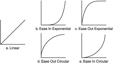
The tween code uses a linear tween by default, but many different tweens can be added. Figure 8.20 shows a number of these tweens.
There are many Flash tween functions available on the internet, and it’s very easy to convert these to C# code.
The Tween class encapsulates the idea of representing a variable’s value over time. Here is the full working class.
public class Tween
{
  double _original;
  double _distance;
  double _current;
  double _totalTimePassed = 0;
  double _totalDuration = 5;
  bool _finished = false;
  TweenFunction _tweenF = null;
  public delegate double TweenFunction(double timePassed, double start,
double distance, double duration);

  public double Value()
  {
    return _current;
  }
  public bool IsFinished()
  {
    return _finished;
  }
  public static double Linear(double timePassed, double start, double
distance, double duration)
  {
    return distance * timePassed / duration +  start;
  }

  public Tween(double start, double end, double time)
  {
    Construct(start, end, time, Tween.Linear);
  }

  public Tween(double start, double end, double time, TweenFunction
tweenF)
  {
    Construct(start, end, time, tweenF);
  }

  public void Construct(double start, double end, double time, TweenFunc-
tion tweenF)
  {
    _distance = end - start;
    _original = start;
    _current = start;
    _totalDuration = time;
    _tweenF = tweenF;
  }

  public void Update(double elapsedTime)
  {
    _totalTimePassed += elapsedTime;
    _current = _tweenF(_totalTimePassed, _original, _distance,
_totalDuration);

    if (_totalTimePassed > _totalDuration)
    {
     _current = _original + _distance;
     _finished = true;
    }
  }
}
There are two constructors and both call the Construct method. The constructors allow a user to specify the type of tween function, or alternatively just use the default linear change over time. A tween function is defined by the TweenFunction delegate. The only implementation of the TweenFunction delegate in this class is the Linear function. Its use can be seen in the default constructor.
Construct(start, end, time, Tween.Linear);
The Construct method records the start value of the tween, the end value, and the time in which the tween can perform this operation. A tween function can also be passed in to determine how the value will be changed over time. The Construct method records these values and works out the distance from the start value to the end value. This distance is passed on to the relevant tween function.
The Tween object is updated every frame and the time elapsed is summed each Update call. This way the Tween object knows how far through the tween it is. The tween function delegate modifies the current value of the tween. Finally, the Update method checks if the tween has finished, and if it has, it sets the finish flag to true.
With only a linear function, the Tween class isn’t very exciting, so here are some more functions that can be added. These are shown in Figure 8.20.
public static double EaseOutExpo(double timePassed, double start, double
distance, double duration)
{
if (timePassed == duration)
{
  return start + distance;
}
return distance * (-Math.Pow(2, -10 * timePassed / duration) + 1) + start;
}

public static double EaseInExpo(double timePassed, double start, double
distance, double duration)
{
  if (timePassed == 0)
  {
    return start;
  }
  else
  {
    return distance * Math.Pow(2, 10 * (timePassed / duration - 1)) + start;
  }
}

public static double EaseOutCirc(double timePassed, double start, double
distance, double duration)
{
  return distance * Math.Sqrt(1 - (timePassed = timePassed / duration - 1) *
timePassed) + start;
}

public static double EaseInCirc(double timePassed, double start, double
distance, double duration)
{
  return -distance * (Math.Sqrt(1 - (timePassed /= duration) * timePassed)
- 1) + start;
}
Now that the tween class has been created, it is time to show off some of its power. As always, this begins with a new game state being created. This one is named TweenTestState.
This state requires the face texture used earlier in the book to be added to the project and its “Copy To Output Directory” property set to “Copy if newer”. In the form constructor the face texture should be loaded into the TextureManager.
_textureManager.LoadTexture("face", "face_alpha.tif");
With the texture loaded it can be now be used to make a sprite in the TweenTestState class.
class TweenTestState : IGameObject
{
  Sprite _faceSprite = new Sprite();
  Renderer _renderer = new Renderer();
  Tween _tween = new Tween(0, 256, 5);
  public TweenTestState(TextureManager textureManager)
  {
    _faceSprite.Texture = textureManager.Get("face");
  }

  #region IGameObject Members

  public void Process(double elapsedTime)
  {
    if (_tween.IsFinished() != true)
    {
     _tween.Process(elapsedTime);
     _faceSprite.SetWidth((float)_tween.Value());
     _faceSprite.SetHeight((float)_tween.Value());
    }
  }

  public void Render()
  {
    Gl.glClearColor(0.0f, 0.0f, 0.0f, 1.0f);
    Gl.glClear(Gl.GL_COLOR_BUFFER_BIT);
    _renderer.DrawSprite(_faceSprite);
    _renderer.Render();
  }
  #endregion
}
The tween increases the width and height of the sprite from 0 all the way up to 256. Run the code and check out the animation. The sprite will enlarge in a smooth pleasing way. The next change is only a tiny modification to the code but results in a big change.
Tween _tween = new Tween(0, 256, 5, Tween.EaseInExpo);
Run the program again and now the sprite will slowly expand. Then the change will accelerate as it comes to full size. One small change has totally changed the way the animation plays out. This is a great way to tweak existing animations. Try the rest of the tween functions and see what they do, play around with the rest of the arguments, and get a feel for how it all works.
Tween _alphaTween = new Tween(0, 1, 5, Tween.EaseInCirc);
Color _color = new Color(1, 1, 1, 0);
public void Process(double elapsedTime)
{
  if (_tween.IsFinished() != true)
  {
    _tween.Process(elapsedTime);
    _faceSprite.SetWidth((float)_tween.Value());
    _faceSprite.SetHeight((float)_tween.Value());
  }

  if (_alphaTween.IsFinished() != true)
  {
    _alphaTween.Process(elapsedTime);
    _color.Alpha = (float)_alphaTween.Value();
    _faceSprite.SetColor(_color);
  }
}
Another tween has been added. This tween takes the transparency of the sprite from zero up to full opacity. This is a great method to use to fade in text. The position of the sprite can also be altered with a tween. Try tweening the sprite from off-screen to the center. Another good exercise would be to tween the sprite opacity from zero to one and then set off a tween that will reverse it; tweening from one to zero. These can then be called one after another, looping the tween.
Matrices are used throughout graphics programming. There are many different applications of matrices, but this section will concentrate only on those related to graphics and game programming.
Matrices are mathematical structures that provide a convenient way to describe and perform a number of operations on a 3D model or sprite made from a quad. These operations include transforming (moving the models around 3D space), rotating, scaling, sheering (making the shape lean in a certain direction), and projecting (the conversion of a point in 3D space to 2D space, for example). Many of these operations can be done manually; for instance, our sprite class already performs the translation operation by adding vectors to each vertex position.
A matrix has several advantages over a vector when performing such operations. Different matrices can be combined with their operation into a single matrix that defines the combination of all those operations. For instance, a matrix that rotates a model 90 degrees, a matrix that scales a model up two times, and a matrix that moves the model two miles to the left can all be combined into a single matrix that does all these operations at once. This is done by matrix multiplication—multiply the matrices together and the result will be a matrix that is the combination of all the operations.
Combining operations is not the only advantage to matrices. A matrix can be inverted; this will perform the opposite operation that the original matrix would have performed. If a rotation matrix was created to rotate 5 degrees around the Z axis, and it was then applied to a model, the model’s original position could be restored by inverting the matrix and applying it again. Matrices are applied to a model by multiplying each vertex by the matrix.
Matrix math can be quite dense; few game developers would be able to write the code for matrix multiplication immediately when asked. The actual matrix operations are quite simple, but it can take a while to understand them completely. Don’t be discouraged, and if you want a more thorough understanding check the recommended reading section in Appendix A.
A matrix is a grid of numbers. Like vectors, matrices come in many dimensions. The vector we have defined has a dimension of three—X, Y, and Z. The most commonly used matrix in 3D graphics is 4x4, as is shown in Figure 8.21.
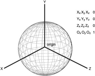
Figure 8.21 shows the matrix described as three axis vectors and one position vector: the origin. XxXyXz describes the x vector, YxYyYz the y vector, ZxZyZz the z vector, and the origin vector is described as OxOyOz. These three vectors are the axis of the model and its origin. These can be used to quickly determine an object’s position and the direction it faces on the X, Y, and Z axes. If the axes are all normalized, then the object isn’t scaled; if the axes all have a length of two, then the object is scaled to be twice as big. This is a visual way of thinking about matrices that makes them easier to use.
The final column in Figure 8.21 is [0, 0, 0, 1]. The values in this column will never change; they are only used when computing projections (from 3D to 2D space). Such projection operations aren’t that common so the matrix we’ll use will be 4x3. The end column will always be [0, 0, 0, 1].
Before covering matrix operations, it’s time to make the basic class.
public class Matrix
{
  double _m11, _m12, _m13;
  double _m21, _m22, _m23;
  double _m31, _m32, _m33;
  double _m41, _m42, _m43;
}
Here is the Matrix class based on a 4x3 layout. Its member variables are laid out in a similar way to Figure 8.18 but there is no fourth column (we know the fourth column will always be [0, 0, 0, 1] so the values don’t need to be stored). The Vector, Color, and Point components were all structures, but the Matrix is a larger component so it has been declared as a class.
In the following sections, we’ll flesh out the Matrix class and add some operations to it.
The identity matrix is the matrix that when multiplied by any other matrix will not modify it in any way. The number 1 is an example of an identity in real numbers; any number multiplied by 1 results in the original number unchanged.
All matrix identities are square. Here are the identities for a 3 × 3 matrix and a 4 × 4 matrix.

When creating a matrix operation, the identity is the perfect starting place. It doesn’t do anything to the vertices it’s applied to so only the changes you apply on top of the identity will be performed. If a matrix of all zeros was applied to any model, then that model would disappear; all its vertices would be collapsed down to a singularity like a black hole. The matrix class should by default be initialized to the identity matrix.
Add these definitions to your matrix class.
public static readonly Matrix Identity =
  new Matrix(new Vector(1, 0, 0),
             new Vector(0, 1, 0),
             new Vector(0, 0, 1),
             new Vector(0, 0, 1));

public Matrix() : this (Identity)
{

}

public Matrix(Matrix m)
{
 _m11 = m._m11;
 _m12 = m._m12;
 _m13 = m._m13;

 _m21 = m._m21;
 _m22 = m._m22;
 _m23 = m._m23;
 _m31 = m._m31;
 _m32 = m._m32;
 _m33 = m._m33;
 _m41 = m._m41;
 _m42 = m._m42;
 _m43 = m._m43;
}

public Matrix(Vector x, Vector y, Vector z, Vector o)
{
  _m11 = x.X; _m12 = x.Y; _m13 = x.Z;
  _m21 = y.X; _m22 = y.Y; _m23 = y.Z;
  _m31 = z.X; _m32 = z.Y; _m33 = z.Z;
  _m41 = o.X; _m42 = o.Y; _m43 = o.Z;
}
This code adds a constant identity matrix and a number of constructors. The default constructor initializes the members to the identity matrix by passing the identity matrix to a copy constructor. The second constructor is the copy constructor. A copy constructor is a constructor that is called with one parameter, which is the same type as the object being constructed. The copy constructor copies all its member data so that the created object is exactly the same. The final constructor takes in a vector for each axis and one vector for the origin.
The most important methods of the Matrix class are its multiplication methods; these are used to combine matrices and transform on vertex positions. Matrix multiplication can only be performed if the width of the first matrix equals the height of the second. Matrix-matrix and vector-matrix multiplication is performed using the same algorithm.
Here is the definition.
Ci,k = Ai,jBj,k
C is the result from the multiplication, i is the length of the rows in matrix A, and k is the length of the columns in matrix B. The j is the number of possible summations of i and k. In matrix multiplication, different-shaped matrices can result from the original shapes of the matrices that are multiplied. Again, don’t worry if the math all seems a little intimidating; knowing how and when to use a matrix is the most important lesson to take away.
The width of our matrix equals its height if we remember to include the final column of [0, 0, 0, 1]. Therefore, using the multiplication definition, the code for the matrix-matrix multiplication is as follows:
public static Matrix operator *(Matrix mA, Matrix mB)
{
  Matrix result = new Matrix();

  result._m11 = mA._m11 * mB._m11 + mA._m12 * mB._m21 + mA._m13 * mB._m31;
  result._m12 = mA._m11 * mB._m12 + mA._m12 * mB._m22 + mA._m13 * mB._m32;
  result._m13 = mA._m11 * mB._m13 + mA._m12 * mB._m23 + mA._m13 * mB._m33;

  result._m21 = mA._m21 * mB._m11 + mA._m22 * mB._m21 + mA._m23 * mB._m31;
  result._m22 = mA._m21 * mB._m12 + mA._m22 * mB._m22 + mA._m23 * mB._m32;
  result._m23 = mA._m21 * mB._m13 + mA._m22 * mB._m23 + mA._m23 * mB._m33;

  result._m31 = mA._m31 * mB._m11 + mA._m32 * mB._m21 + mA._m33 * mB._m31;
  result._m32 = mA._m31 * mB._m12 + mA._m32 * mB._m22 + mA._m33 * mB._m32;
  result._m33 = mA._m31 * mB._m13 + mA._m32 * mB._m23 + mA._m33 * mB._m33;

  result._m41 = mA._m41 * mB._m11 + mA._m42 * mB._m21 + mA._m43 * mA._m31 +
mB._m41;
  result._m42 = mA._m41 * mB._m12 + mA._m42 * mB._m22 + mA._m43 * mB._m32 +
mB._m42;
  result._m43 = mA._m41 * mB._m13 + mA._m42 * mB._m23 + mA._m43 * mB._m33 +
mB._m43;

  return result;
}
The vector matrix multiplication is similar.
public static Vector operator *(Vector v, Matrix m)
{

  return new Vector(v.X * m._m11 + v.Y * m._m21 + v.Z * m._m31 + m._m41,
         v.X * m._m12 + v.Y * m._m22 + v.Z * m._m32 + m._m42,
         v.X * m._m13 + v.Y * m._m23 + v.Z * m._m33 + m._m43);
}
Translation is a pretty simple operation. The last row of the vector is the origin of the object; it is the translation. Creating a matrix to alter the translation is just the identity matrix with the last row altered. Here is the translation matrix.
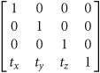
The code is also simple.
public void SetTranslation(Vector translation)
{
  _m41 = translation.X;
  _m42 = translation.Y;
  _m43 = translation.Z;
}

public Vector GetTranslation()
{
  return new Vector(_m41, _m42, _m43);
}
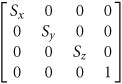
The scaling matrix is also quite easy to understand. Remember, each row represents an axis. The first row of the matrix can be thought of as a vector. This vector is the X axis of whatever is being scaled; the greater its Xx dimension the greater it’s scaled in that direction. The second row is the Y axis, the third row is the Z axis, and they too can be thought of as vectors. If each of the vectors has a length of 2, then the object is scaled uniformly along each axis.
public void SetScale(Vector scale)
{
  _m11 = scale.X;
  _m22 = scale.Y;
  _m33 = scale.Z;
}
public Vector GetScale()
{
  Vector result = new Vector();
  result.X = (new Vector(_m11, _m12, _m13)).Length();
  result.Y = (new Vector(_m21, _m22, _m23)).Length();
  result.Z = (new Vector(_m31, _m32, _m33)).Length();
  return result;
}
The scale can also be non-uniform. It can be scaled more along one axis than the others. To find out the scale along a particular axis, just get the row and convert it to a vector; then apply the vector length operation, and this will give you the scaling amount.
The math for rotating around an arbitrary axis is a lot more complicated than the previous matrices. It’s not important to know exactly how this works; it’s more important to know the result. The rotation matrix is made from an axis u which is defined as a normalized vector and a scalar value (θ) that describes the amount of rotation in radians. If the model you wanted to rotate was a wine cork then the normalized vector u could be represented by a needle pushed through the cork. The angle (θ) represents the amount the needle is rotated which in turn rotates the cork.
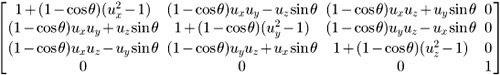
public void SetRotate(Vector axis, double angle)
{
  double angleSin = Math.Sin(angle);
  double angleCos = Math.Cos(angle);
  double a = 1.0 - angleCos;
  double ax = a * axis.X;
  double ay = a * axis.Y;
  double az = a * axis.Z;
  _m11 = ax * axis.X + angleCos;
  _m12 = ax * axis.Y + axis.Z * angleSin;
  _m13 = ax * axis.Z - axis.Y * angleSin;

  _m21 = ay * axis.X - axis.Z * angleSin;
  _m22 = ay * axis.Y + angleCos;
  _m23 = ay * axis.Z + axis.X * angleSin;

  _m31 = az * axis.X + axis.Y * angleSin;
  _m32 = az * axis.Y - axis.X * angleSin;
  _m33 = az * axis.Z + angleCos;
}
Sine and cosine can be expensive operations if they are used many times a frame, and for that reason, their use in the code is minimized. The axis vector should be normalized, but there is no check in the SetRotate function.
The inverse is very useful for reversing the operations of a given matrix. To calculate the inverse, the determinate of the matrix is required. Every square matrix has its own determinate. A matrix is invertible only if the determinate doesn’t equal zero.
public double Determinate()
{
  return _m11 * (_m22 * _m33 - _m23 * _m32) +
         _m12 * (_m23 * _m31 - _m21 * _m33) +
         _m13 * (_m21 * _m32 - _m22 * _m31);
}
The determinate can then be used to calculate the inverse of the top 3×3 of the matrix—the scale and rotation parts. The translation part of the matrix is calculated manually.
public Matrix Inverse()
{
  double determinate = Determinate();
  System.Diagnostics.Debug.Assert(Math.Abs(determinate)>
Double.Epsilon,
"No determinate");

  double oneOverDet = 1.0 / determinate;

  Matrix result = new Matrix();
  result._m11 = (_m22 * _m33 - _m23 * _m32) * oneOverDet;
  result._m12 = (_m13 * _m32 - _m12 * _m33) * oneOverDet;
  result._m13 = (_m12 * _m23 - _m13 * _m22) * oneOverDet;

  result._m21 = (_m23 * _m31 - _m21 * _m33) * oneOverDet;
  result._m22 = (_m11 * _m33 - _m13 * _m31) * oneOverDet;
  result._m23 = (_m13 * _m21 - _m11 * _m23) * oneOverDet;

  result._m31 = (_m21 * _m32 - _m22 * _m31) * oneOverDet;
  result._m32 = (_m12 * _m31 - _m11 * _m32) * oneOverDet;
  result._m33 = (_m11 * _m22 - _m12 * _m21) * oneOverDet;

  result._m41 = -(_m41 * result._m11 + _m42 * result._m21 + _m43 *
result._m31);
  result._m42 = -(_m41 * result._m12 + _m42 * result._m22 + _m43 *
result._m32);
  result._m43 = -(_m41 * result._m13 + _m42 * result._m23 + _m43 *
result._m33);

  return result;
}
With this code, any matrix we will be using can be inverted.
That’s it for the Matrix class; it’s now useful for both 2D and 3D applications. Next, we will apply it.
Create a new game state called MatrixTestState. This state will draw a sprite and apply various matrices to that sprite. Here is the code to just draw the sprite, which should be quite familiar to you by now.
class MatrixTestState : IGameObject
{
  Sprite _faceSprite = new Sprite();
  Renderer _renderer = new Renderer();
  public MatrixTestState(TextureManager textureManager)
  {
    _faceSprite.Texture = textureManager.Get("face");
    Gl.glEnable(Gl.GL_TEXTURE_2D);
  }
  public void Render()
  {
    Gl.glClearColor(0.0f, 0.0f, 0.0f, 1.0f);
    Gl.glClear(Gl.GL_COLOR_BUFFER_BIT);
    _renderer.DrawSprite(_faceSprite);
    _renderer.Render();
  }
  public void Update(double elapsedTime)
  {
  }
}
This code uses the face sprite from the earlier chapters. The matrices will be applied to the sprite in the MatrixTestState constructor.
Matrix m = new Matrix();
m.SetRotate(new Vector(0, 0, 1), Math.PI/5);

for (int i = 0; i < _faceSprite.VertexPositions.Length; i++ )
{
  _faceSprite.VertexPositions[i] *= m;
}
Run the code and you will notice that the face has been rotated. The rotation is done along the Z axis (0, 0, 1); this is the axis that comes out of the screen. Imagine the face sprite is a piece of paper on the screen. To rotate it, you stick a pin through it, attaching it to the screen and damaging your monitor! The pin represents the Z axis. Spinning the paper sprite now will spin it around that axis. For 2D objects in an orthographic projection, the Y axis and Z axis aren’t very useful for rotations, but they would be useful in a 3D game. Any normalized axis can be used to rotate an object, not just the major X, Y, and Z axes.
In the code example, the rotation amount is given in radians Math.PI/5, which is equivalent to 36 degrees. The rotation matrix is applied to each vertex that makes up the sprite. We’ve now used one matrix that slightly rotates the sprite; let’s add another matrix that will scale it. The scale matrix will be combined with the rotation matrix by multiplying them. Modify the existing code in the constructor so it looks like the code here:
Matrix m = new Matrix();
m.SetRotate(new Vector(0, 0, 1),Math.PI/5);

Matrix mScale = new Matrix();
mScale.SetScale(new Vector(2.0, 2.0, 0.0));

m *= mScale;

for (int i = 0; i < _faceSprite.VertexPositions.Length; i++ )
{
  _faceSprite.VertexPositions[i] *= m;
}
This code creates a scale matrix that scales the X and Y axis by 2. This is combined with the rotation matrix by multiplying them together and assigning the result to the matrix m. This new combined m matrix is then applied to the face sprite, scaling and rotating it. The order of matrix multiplication is important; multiplying matrix a by matrix b is not guaranteed to have the same result as matrix b by matrix a. Play around with different matrices to get a good idea of how they work together.
The final code snippet will demonstrate the inverse matrix. The inverse matrix reverses a matrix operation. If rotate-scale matrix was multiplied by its inverse matrix, then the result would be the identity matrix. The identity matrix will not have any effect on the sprite when it is applied to it.
Matrix m = new Matrix();
m.SetRotate(new Vector(0, 0, 1),Math.PI/5);

Matrix mScale = new Matrix();
mScale.SetScale(new Vector(2.0, 2.0, 2.0));

m *= mScale;
Vector scale = m.GetScale();
m *= m.Inverse();

for (int i = 0; i < _faceSprite.VertexPositions.Length; i++ )
{
  _faceSprite.VertexPositions[i] *= m;
}
Experiment with the translation matrix as well, and try combining the matrices in different orders.
The sprite currently has a translation method SetPosition, but it doesn’t have similar SetScale or SetRotation methods. These would be very useful functions to add and would be great to use with the tween functions. Modifying the sprite class is quite simple but some additional members and methods need to be added.
double _scaleX = 1;
double _scaleY = 1;
double _rotation = 0;
double _positionX = 0;
double _positionY = 0;

public void ApplyMatrix(Matrix m)
{
  for (int i = 0; i < VertexPositions.Length; i++)
  {
    VertexPositions[i] *= m;
  }
}
public void SetPosition(Vector position)
{
  Matrix m = new Matrix();
  m.SetTranslation(new Vector(_positionX, _positionY, 0));
  ApplyMatrix(m.Inverse());
  m.SetTranslation(position);
  ApplyMatrix(m);
  _positionX = position.X;
  _positionY = position.Y;
}
public void SetScale(double x, double y)
{
  double oldX = _positionX;
  double oldY = _positionY;
  SetPosition(0, 0);
  Matrix mScale = new Matrix();
  mScale.SetScale(new Vector(_scaleX, _scaleY, 1));
  mScale = mScale.Inverse();
  ApplyMatrix(mScale);
  mScale = new Matrix();
  mScale.SetScale(new Vector(x, y, 1));
  ApplyMatrix(mScale);
  SetPosition(oldX, oldY);
  _scaleX = x;
  _scaleY = y;
}

public void SetRotation(double rotation)
{
  double oldX = _positionX;
  double oldY = _positionY;
  SetPosition(0, 0);
  Matrix mRot = new Matrix();
  mRot.SetRotate(new Vector(0, 0, 1), _rotation);
  ApplyMatrix(mRot.Inverse());
  mRot = new Matrix();
  mRot.SetRotate(new Vector(0, 0, 1), rotation);
  ApplyMatrix(mRot);
  SetPosition(oldX, oldY);
  _rotation = rotation;
}
These extra functions allow the sprite to be rotated and scaled as needed. They are a little more expensive, but it’s very easy to transfer these functions to a 3D model. These functions can be trimmed down quite a bit to gain a performance boost.
It’s important to focus on games and only optimize when it’s needed. For most games, the matrix class is already as fast as it needs to be, but programmers, as a rule, like to optimize, so here are some pointers. Matrices involve a lot of arithmetic so reducing the use of matrices is generally a good thing. The most optimized code is the code that never runs.
At the moment, each sprite is made of two triangles, making a total of six vertices, but really, a sprite could be made with a mere four vertices. A good starting point to address this would be investigating the index buffer functions in the OpenGL documentation.
Modern CPUs have specialized hardware, SIMD (which stands for Single Instruction, Multiple Data), to do matrix and vector operations. The SIMD instructions dramatically increase the speed of matrix calculations. Unfortunately, at the time of writing, SIMD operations are only supported under the Mono implementation of C#.
Most of your test programs will be built in debug mode. Release mode is much faster. There is also an option to turn on optimization if you right-click the project in the solution explorer and choose Properties.
Garbage collection is one thing that can make C# slower than a language like C++. The best way to avoid slow down from the garbage collection is to reduce the amount of objects created in the main loop. You are creating an object any time you use the keyword new. Objects are best created once in the constructor or defined as a member of the object and not in the process or render loops.
Some of the matrix operations create matrices. It makes them convenient to use and a lot of the object creation will be optimized away, but they can be made more efficient. When debugging, if you right-click the window, there’s an option called “Go to Disassembly.” This shows the IL (intermediate language) generated by each line of the C# code. The fewer IL instructions, the faster the code will run, provided the release build optimization doesn’t already remove these IL instructions for you. Unfortunately, any optimizations the compiler performs will generally not be shown in the disassembly.