By Beau Williamson
This chapter appears in the book Developing IP Multicast Networks, Volume I by Cisco Press (ISBN 1-57870-077-9).
For a review of multicast, see Appendix I, "Overview of IP Multicast."
Protocol Independent Multicast sparse mode (PIM-SM), like PIM dense mode (PIM-DM), uses the unicast routing table to perform the Reverse Path Forwarding (RPF) check function instead of maintaining a separate multicast route table. Therefore, regardless of which unicast routing protocol(s) is (are) used to populate the unicast routing table (including static routes), PIM-SM uses this information to perform multicast forwarding; hence, it too is protocol independent.
Some key characteristics of PIM-SM are
Protocol independent (uses unicast route table for RPF check)
No separate multicast routing protocol (à la Distance Vector Multicast Routing Protocol [DVMRP)
Explicit Join behavior
Classless (as long as classless unicast routing is in use)
This chapter provides an overview of the basic mechanisms used by PIM-SM, which include
Explicit Join model
Shared trees
Source registration
Designated Router (DR)
SPT switchover
State-Refresh
Rendezvous point (RP) discovery
In addition, some of the mechanisms that are used in PIM-DM are also used by PIM-SM. These include
PIM Neighbor Discovery
PIM Asserts
This chapter does not repeat these topics. However, the reader is encouraged to review these topics before proceeding with this chapter. Finally, it's important to keep in mind that this chapter is strictly an overview of PIM-SM and covers only the basics.
Just as its name implies, PIM-SM conforms to the sparse mode model where multicast traffic is only sent to locations of the network that specifically request it. In PIM-SM, this is accomplished via PIM Joins, which are sent hop by hop toward the root node of tree. (The root node of a tree in PIM-SM is the RP in the case of a shared tree or the first-hop router that is directly connected to the multicast source in the case of a SPT.) As this Join travels up the tree, routers along the path set up multicast forwarding state so that the requested multicast traffic will be forwarded back down the tree.
Likewise, when multicast traffic is no longer needed, a router sends a PIM Prune up the tree toward the root node to prune off the unnecessary traffic. As this PIM Prune travels hop by hop up the tree, each router updates its forwarding state appropriately. This update often results in the deletion of the forwarding state associated with a multicast group or source.
The key point here is that in the Explicit Join model, forwarding state in the routers is set up as a result of these Joins. This is a substantial departure from flood-and-prune protocols such as PIM-DM where router forwarding state is set up by the arrival of multicast data.
PIM-SM operation centers around a single, unidirectional shared tree whose root node is called the rendezvous point (RP). These shared trees are sometimes called RP trees because they are rooted at the RP. (Shared trees or RP trees are frequently known as RPTs so as to avoid confusion with source trees, which are also known as shortest path trees; hence, the acronym SPTs.)
Last-hop routers (that is, routers that have a directly connected receiver for the multicast group) that need to receive the traffic from a specific multicast group, join this shared tree. When the last-hop router no longer needs the traffic of a specific multicast group (that is, when there are no longer any directly connected receivers for the multicast group), the router prunes itself from the shared tree.
Because PIM-SM uses a unidirectional shared tree where traffic can only flow down the tree, sources must register with the RP to get their multicast traffic to flow down the shared tree (via the RP). This registration process actually triggers an SPT Join by the RP toward the Source when there are active receivers for the group in the network. (SPT Joins are described in more detail in the section, "PIM-SM Shortest Path Trees," and registers are described in more detail in the Source Registration section.)
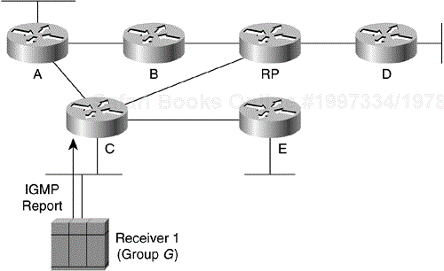
Figure 13-1 shows the first step of a Shared Tree Join in a sample PIM-SM. In this step, a single host (Receiver 1) has just joined multicast Group G via an Internet Group Membership Protocol (IGMP) Membership Report.
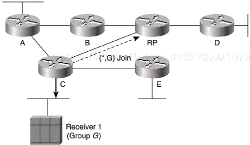
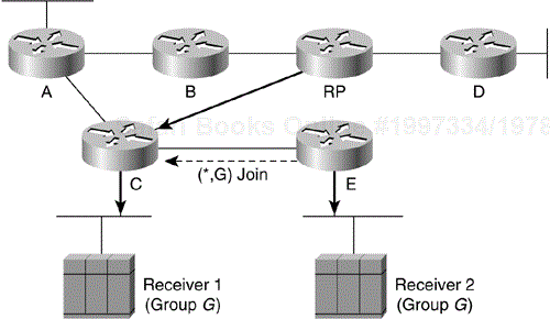
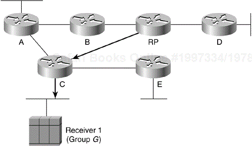
Because Receiver 1 is the first host to join the multicast group in the example, Router C had to create a (*, G) state entry in its multicast routing table for this multicast group. Router C then places the Ethernet interface in the outgoing interface list of the (*, G) entry as shown by the solid arrow in Figure 13-2. Because Router C had to create a new (*, G) state entry, it must also send a PIM (*, G) Join (indicated by the dashed arrow in Figure 13-2) toward the RP to join the shared tree. (Router C uses its unicast routing table to determine the interface toward the RP.)
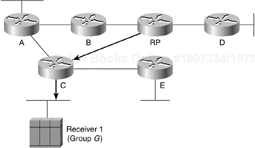
The RP receives the (*, G) Join, and because it too had no previous state for multicast group G, creates a (*, G) state entry in its multicast routing table and adds the link to Router C to the outgoing interface list. At this point, a shared tree for multicast Group G has been constructed from the RP to Router C and Receiver 1, as shown by the solid lines in Figure 13-3. Now, any traffic for multicast Group G that reaches the RP can flow down the shared tree to Receiver 1.
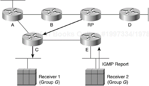
Let's continue the example and assume that another host (Receiver 2) joins the multicast group as shown in Figure 13-4. Again, the host has signaled its desire to join multicast Group G by using an IGMP Membership Report that was received by Router E.
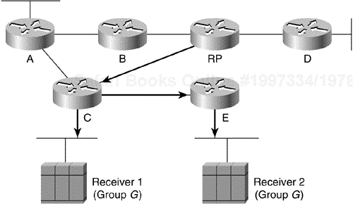
Because Router E didn't have any state for multicast Group G, it creates a (*, G) state entry in its multicast routing table and adds the Ethernet interface to its outgoing interface list (shown by the solid arrow in Figure 13-5). Because Router E had to create a new (*, G) entry, it sends a (*, G) Join (indicated by the dashed arrow in Figure 13-5) toward the RP to join the shared tree for Group G.
When Router C receives the (*, G) Join from Router E, it finds that it already has (*, G) state for Group G (that is, it's already on the shared tree for this group). As a result, Router C simply adds the link to Router E to the outgoing interface list in its (*, G) entry.
Figure 13-6 shows the resulting shared tree (indicated by the solid arrows) that includes Routers C and E along with their directly connected hosts (Receiver 1 and Receiver 2).
Because PIM-SM uses the Explicit Join model to build distribution trees as needed, it also uses Prunes to tear down the trees when they are no longer needed. (We could just stop sending periodic Joins to refresh the tree and allow the tree branches to time out. However, that isn't a very efficient usage of network resources.)
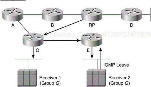
As an example, assume that Receiver 2 leaves multicast Group G by sending an IGMP Leave message (shown in Figure 13-7).
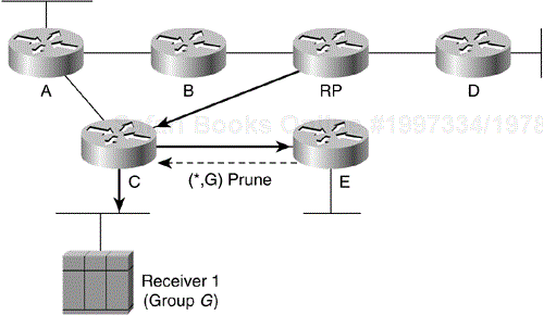
Because Receiver 2 was the only host joined to the group on Router E's Ethernet interface, this interface is removed from the outgoing interface list in its (*, G) entry. (This is represented by the removal of the arrow on Router E's Ethernet in Figure 7-8.) When the interface is removed, the outgoing interface list for this (*, G) entry is null (empty), which indicates that Router E no longer needs the traffic for this group. Router E responds to the fact that its outgoing interface list is now null by sending a (*, G) Prune (shown in Figure 13-8) toward the RP to prune itself off the shared tree.
When Router C receives this Prune, it removes the link to Router E from the outgoing interface list of the (*, G) entry (as indicated by the removal of the arrow between Router C and Router E in Figure 13-9). However, because Router C still has a directly connected host for the group (Receiver 1), the outgoing interface list for the (*, G) entry is not null (empty). Therefore, Router C must remain on the shared tree, and a Prune is not sent up the shared tree toward the RP.
One of the primary advantages of PIM-SM is that, unlike other sparse mode protocols (such as core-based trees), it doesn't limit us to receiving multicast traffic only via the shared tree. Just as it is possible to use the Explicit Join mechanism to join the shared tree, whose root is the RP, this mechanism can be used to join the SPT whose root is a particular source. The advantage should be obvious. By joining the SPT, multicast traffic is routed directly to the receivers without having to go through the RP, thereby reducing network latency and possible congestion at the RP. On the other hand, the disadvantage is that routers must create and maintain (S, G) state entries in their multicast routing tables along the (S, G) SPT. This action, of course, consumes more router resources.
Still, the overall amount of (S, G) information maintained by the routers in a PIM-SM network that uses SPTs is generally much less than is necessary for dense mode protocols. The reason is that the Flood-and-Prune mechanism used by dense mode protocols results in all routers in the network maintaining (S, G) state entries in their multicast routing tables for all active sources. This is true even if there are no active receivers for the groups to which the sources are transmitting. By joining SPTs in PIM-SM, we gain the advantage of an optimal distribution tree without suffering from the overhead and inefficiencies associated with other dense mode protocols such as PIM-DM, DVMRP, and Multicast Open Shortest Path First (MOSPF). (By now, you are probably beginning to understand why PIM-SM is generally recommended over other dense mode protocols.)
This leads to an obvious question: If using SPTs in PIM-SM is so desirable, why join the shared tree in the first place? The problem is that without the shared tree to deliver the first few multicast packets from a source, routers have no way of knowing that a source is active.
Note
Several methods (including the use of dynamic Domain Name System [DNS] entries) have been proposed to tell routers which sources are currently active for which groups. Using this information, a router could immediately and directly join the SPT of all active sources in the group. This would eliminate the need for a shared tree and its associated Core or RP. Unfortunately, none of the methods proposed to date have met with much acceptance in the Internet community.
The sections that follow present the basic concepts of building SPTs using (S, G) Joins and Prunes. Keep in mind that the goal here is to understand the basic concepts of joining the SPT. The details as to why and when PIM-SM routers actually join the SPT are discussed later.
As you recall from the section "Shared Tree Joins," routers send a (*, G) Join toward the RP to join the shared tree and receive multicast traffic for Group G. However, by sending an (S, G) Join toward Source S, a router can just as easily join the SPT for Source S and receive multicast traffic being sent by S to Group G.
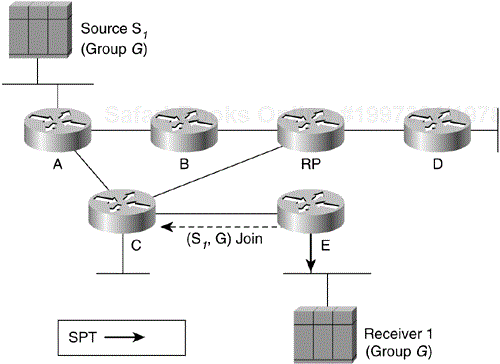
Figure 13-10 shows an example of an (S, G) Join being sent toward an active source to join the SPT. (The solid arrows in the drawing indicate the path of the SPT down which traffic from Source S1 flows.) In this example, Receiver 1 has already joined Group G (indicated by the solid arrow from Router E).
For the sake of this example, assume that Router E somehow magically knows that Source S1 is active for Group G.
Note
In reality, Router E would have learned that Source S1 is active because it would have received a packet from the source via the shared tree. However, to make the point that PIM SPTs are independent from shared trees (and to simplify this example), we are going to ignore this minor detail and concentrate on the fact that a router can explicitly join a SPT just as a router can join the shared tree.
Because Router E wants to join the SPT for Source S1, it sends an (S1, G) Join toward the source. Router E determines the correct interface to send this Join out by calculating the RPF interface toward Source S1. (The RPF interface calculation uses the unicast routing table, which in turn indicates that Router C is the next-hop router to Source S1.)
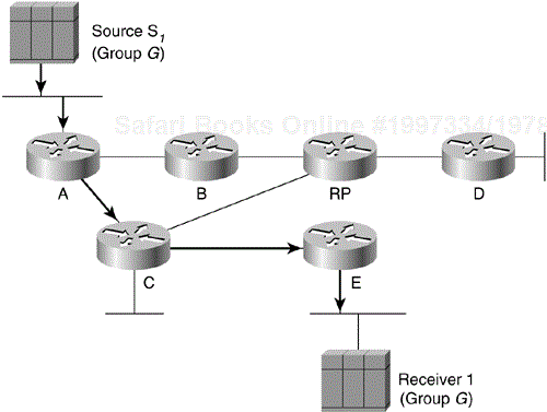
When Router C receives the (S1, G) Join, it creates an (S1, G) entry in its multicast forwarding table and adds the interface on which the Join was received to the entry's outgoing interface list (indicated by the solid arrow from Router C to Router E in Figure 13-11). Because Router C had to create state for (S1, G), it also sends an (S1, G) Join (as shown by the dashed arrow in Figure 13-11) toward the source.
Finally, when Router A receives the (S1, G) Join, it adds the link to Router C to the outgoing interface list of its existing (S1, G) entry as shown by the solid arrow in Figure 13-12. (Router A is referred to as the first hop router for Source S1 and would have already created an (S1, G) entry as soon as it received the first packet from the source.)
SPTs can be pruned by using (S1, G) Prunes in the same manner that shared trees were pruned by using (*, G) Prunes.
Note
Again, the prune examples in this section do not cover the situation where an (S, G) prune is being sent on a multi-access network (such as an Ethernet segment) with several other PIM-SM routers still joined to the same SPT.
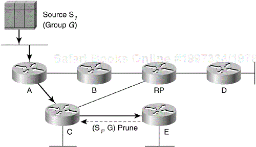
Continuing with the SPT example, assume that Router E no longer has a directly connected receiver for Group G and therefore has no further need for (S1, G) traffic. Therefore, Router E sends an (S1, G) Prune toward Source S1 (as shown by the dashed arrow in Figure 13-13).
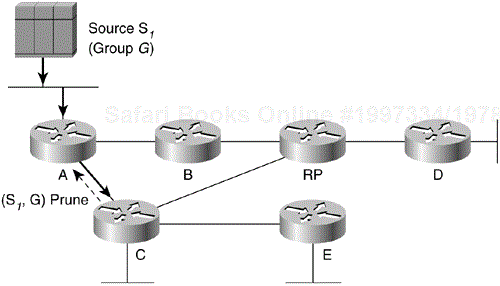
When Router C receives the (S1, G) Prune from Router E, it removes the interface on which the message was received from the outgoing interface list of its (S1, G) entry (indicated by the absence of the solid arrow between Routers C and E in Figure 7\_14). This results in Router C's (S1, G) entry having an empty outgoing interface list. Because the outgoing interface list is now empty, Router C has to send an (S1, G) Prune toward the source S1 (as shown by the dashed arrow in Figure 13-14).
When Router A receives the (S1, G) Prune from Router C, it removes the interface on which it received the Prune from the outgoing interface list of its (S1, G) entry (indicated by the absence of the solid arrow between Routers A and C in Figure 13-15). However, because Router A is the first-hop router for Source S1 (in other words, it is directly connected to the source), no further action is taken. (Router A simply continues to drop any packets from Source S1 because the outgoing interface list in Router A's (S1, G) entry is empty.)
Note
To avoid being flamed by readers who are experienced PIM-SM users, I should point out that the previous SPT examples have been radically simplified to make the concepts of SPTs in PIM-SM easier to understand. Again, the key point here is that the PIM-SM explicit Join/Prune mechanism can be used to Join/Prune SPTs as well as shared trees. This capability becomes important in later sections on source registering and SPT switchover.
Although we have been referring to PIM Prunes and Joins as if they were two individual message types, the reality is that there is only a single PIM Join/Prune message type. Each PIM Join/Prune message contains both a Join list and a Prune list, either one of which may be empty, depending on the information being conveyed up the distribution tree. By including multiple entries in the Join and/or Prune lists, a router may Join/Prune multiple sources and/or groups with a single PIM Join/Prune message. This greatly improves the efficiency of the periodic refresh mechanism because typically only a single message is necessary to refresh an upstream router's state.
The entries in the Join and Prune lists of PIM Join/Prune messages share a common format, containing (among other things) the following information:
Multicast source address—. IP address of the multicast source to Join/Prune. (If the Wildcard flag is set, this is the address of the RP.)
Multicast group address—. Class D multicast group address to Join/Prune.
WC bit (Wildcard flag)—. This entry is a shared tree (*, G) Join/Prune message.
RP bit (RP Tree flag)—. This Join/Prune information is applicable to and should be forwarded up the shared tree.
By manipulating the preceding information in each Join/Prune list entry, various requests may be signaled to an upstream router.
For example, a PIM Join/Prune message with an entry in the Join list of
Source address = 192.16.10.1
Group address = 224.1.1.1
Flags = WC, RP
indicates that this item is a (*, G) (denoted by the WC and RP flags being set) Join for Group 224.1.1.1 whose RP is 192.16.10.1.
A PIM Join/Prune message with an entry in the Prune list of
Source address = 191.1.2.1
Group address = 239.255.1.1
Flags = none
indicates that this is an (S, G) (denoted by the WC and RP flags being clear) Prune for source 191.1.2.1, Group 239.255.1.1.
Note
The reason that this information on the Join/Prune message contents is presented here is that it (particularly the part about the RP flag) will be important when we discuss pruning specific source traffic flows from the shared tree in the Shortest Path Tree Switchover section.
To prevent a stale PIM-SM forwarding state from getting stuck in the routers, it is given a finite lifetime (3 minutes), after which it is deleted. (For example, if an upstream router loses a Prune because of congestion, the associated forwarding state could remain in the router for a long time.) The lifetime is established by associating a 3-minute expiration timer with each (*, G) and (S, G) state entry in the multicast routing table. When these timers expire, the state entry is deleted. As a result, downstream routers must periodically refresh this forwarding state to prevent it from timing out and being deleted. To do so, routers send PIM Join/Prune messages to the appropriate upstream neighbor once a minute. When the upstream neighbor receives the PIM Join/Prune message, it refreshes its existing multicast forwarding state and resets the 3-minute expiration timers.
Routers refresh shared trees by periodically (once a minute) sending (*, G) Joins to the upstream neighbor in the direction of the RP. Additionally, routers refresh SPTs by periodically (once a minute) sending (S, G) Joins to the upstream neighbor in the direction of the source.
These periodic (*, G) and (S, G) Joins are sent by routers as long as they have a nonempty outgoing interface list in their associated (*, G) and (S, G) entries (or a directly connected host for multicast Group G). If these periodic Joins were not sent, multicast state for G would eventually time out (after 3 minutes) and the distribution tree associated with the (*, G) and/or (S, G) multicast routing entry would be torn down.
Note
I find that this periodic refresh mechanism is one of the most frequently overlooked aspects of PIM-SM when students are initially learning PIM-SM fundamentals. This results in confusion regarding the maintenance of certain timers in the multicast forwarding table as well as confusion when this periodic Join message traffic is observed during debugging sessions.
In the section "PIM-SM Shared Trees," you learned how routers use (*, G) Joins to join the shared tree for multicast Group G. However, because PIM-SM uses a unidirectional shared tree, multicast traffic can only flow down this tree. Therefore, multicast sources must somehow get their traffic to the RP so that the traffic can flow down the shared tree. PIM-SM accomplishes this by having the RP join the SPT back to the source so it can receive the source's traffic. First, however, the RP must somehow be notified that the source exists. PIM-SM makes use of PIM Register and Register-Stop messages to implement a source registration process to accomplish this task.
Note
A common misconception is that a source must register before any receivers can join the shared tree. However, receivers can join the shared tree, even though there are currently no active sources. But when a source does become active, the RP then joins the SPT to the source and begins forwarding this traffic down the shared tree. By the same token, sources can register first even if there are no active receivers in the network. Later, when a receiver does join the group, the RP Joins the SPT toward all sources in the group and begins forwarding the group traffic down the shared tree.
The following sections discuss the mechanics of the source registration process that makes use of PIM Register and PIM Register-Stop messages. This process notifies an RP of an active source in the network and delivers the initial multicast packets to the RP to be forwarded down the shared tree. At the end of this section, a detailed, step-by-step example shows this process in action.
PIM Register messages are sent by first-hop DRs (that is, a DR that is directly connected to a multicast source) to the RP. The purpose of the PIM Register message is twofold:
Notify the RP that Source S1 is actively sending to Group G.
Deliver the initial multicast packet(s) sent by Source S1 (each encapsulated inside of a single PIM Register message) to the RP for delivery down the shared tree.
Therefore, when a multicast source begins to transmit, the DR (to which the source is directly connected) receives the multicast packets sent by the source and creates an (S, G) state entry in its multicast routing table. In addition, because the source is directly connected (to the DR), the DR encapsulates each multicast packet in a separate PIM Register message and unicasts it to the RP. (How the DR learns the IP address of the RP is discussed in the RP Discovery section.)
Note
Unlike the other PIM messages that are multicast on a local segment and travel hop by hop through the network, PIM Register messages and their close cousins, PIM Register-Stop messages (discussed in the next subsection) are unicast between the first-hop router and the RP.
When an RP receives a PIM Register message, it first de-encapsulates the message so it can examine the multicast packet inside. If the packet is for an active multicast group (that is, shared tree Joins for the group have been received), the RP forwards the packet down the shared tree. The RP then joins the SPT for Source S1 so that it can receive (S1, G) traffic natively instead of it being sent encapsulated inside of PIM Register messages. If, on the other hand, there is no active shared tree for the group, the RP simply discards the multicast packets and does not send a Join toward the source.
The RP unicasts PIM Register-Stop messages to the first-hop DR, instructing it to stop sending (S1, G) Register messages under any of the following conditions:
When the RP begins receiving multicast traffic from Source S1 via the (S1, G) SPT between the source and the RP.
If the RP has no need for the traffic because there is no active shared tree for the group.
When a first-hop DR receives a Register-Stop message, the router knows that the RP has received the Register message and one of the two conditions above has been met. In either case, the first-hop DR terminates the Register process and stops encapsulating (S1, G) packets in PIM Register messages.
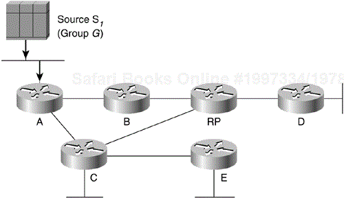
Refer back to the point in the network example (see Figure 13-6) where two receivers have joined multicast Group G (as a result of receiving IGMP Membership Reports from directly connected hosts). At this point, Routers C and E have successfully joined the shared tree back to the RP. Let's now assume that multicast Source S1 begins sending multicast traffic to Group G, as shown in Figure 13-16.
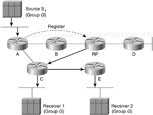
Because Router A is the first-hop DR, it responds to the incoming multicast traffic from Source S1 by encapsulating the multicast packets in a PIM Register message and unicasting them (as shown by the dashed arrow in Figure 13-17) to the RP. (Note that Register messages are not sent hop by hop like other PIM messages, but are sent directly to the RP as a normal unicast packet.)
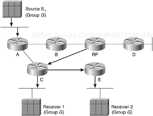
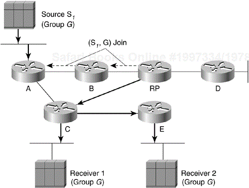
When the RP receives the Register message, the RP de-encapsulates the message and sees that the packet is addressed to multicast Group G. The RP also sees that an active shared tree with a nonempty outgoing interface list exists and therefore sends the de-encapsulated packet down the shared tree (depicted by the solid arrows in Figure 13-17). Furthermore, because an active shared tree exists for this group (with a nonempty outgoing interface list), the RP sends an (S1, G) Join back toward Source S1 to join the SPT and to pull the (S1, G) traffic down to the RP. The (S1, G) Join travels hop by hop back to the first-hop DR, Router A (see Figure 13-18).
When the (S1, G) Join reaches Router A, an (S1, G) SPT has been built from Router A to the RP (indicated by the solid arrows from Router A to the RP in Figure 13-18). Now the (S1, G) traffic begins to flow to the RP via this newly created (S1, G) SPT.
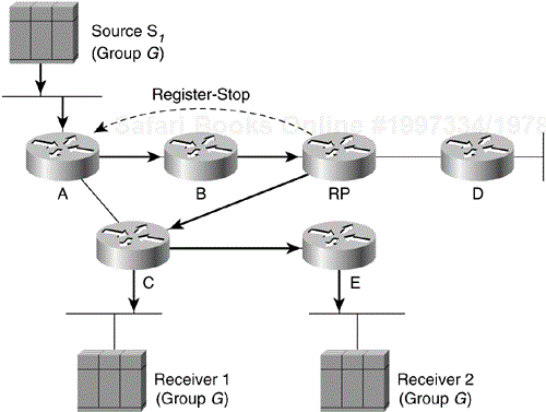
At this point, the RP no longer needs to continue to receive the (S1, G) traffic encapsulated in Register messages, so the RP unicasts a Register-Stop message back to the first-hop DR (Router A), as shown in Figure 13-19.
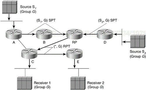
Let's continue with the example and assume another multicast source, S2, connected to Router D begins sending to Group G. The same registration process would occur and would result in the RP joining the (S2, G) SPT to pull the (S1, G) traffic down to the RP so that it could be forwarded on down the shared tree for Group G.
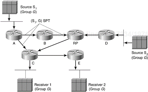
At this point, the RP has joined both the (S1, G) and (S2, G) SPTs, (as seen in Figure 13-20) for the two active sources for Group G. This traffic is being forwarded down the (*, G) shared tree to Receivers 1 and 2. Now, the paths are complete between the sources and the receivers, and multicast traffic is flowing properly.
PIM-SM enables a last hop DR (that is, a DR with directly connected hosts that have joined a multicast group) to switch from the shared tree to the SPT for a specific source. This step is usually accomplished by specifying an SPT-Threshold in terms of bandwidth. If this threshold is exceeded, the last-hop DR joins the SPT. (Cisco routers have this threshold set to zero by default, which means that the SPT is joined as soon the first multicast packet from a source has been received via the shared tree.)
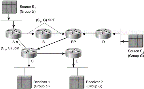
Let's return to the network example at the point where there are two receivers and two active sources (refer to Figure 13-20). Because Router C is a last-hop DR, it has the option of switching to the SPT's for Source S1 and Source S2. (For now, we are concentrating on Source S1 because it is the more interesting case.) To accomplish this, Router C would send an (S1, G) Join toward Source S1, as shown by the dashed arrow in Figure 13-21.
When Router A receives this Join, it adds the interface over which the Join was received to the outgoing interface list of the (S1, G) entry in its multicast forwarding table. This effectively adds the link from Router A to Router C to the (S1, G) SPT, as indicated in Figure 13-22. At this point, (S1, G) multicast traffic can flow directly to Router C via the (S1, G) SPT.
Note
Normally, Group SPT-Thresholds are configured consistently on all routers in the network. If this situation occurred in our example, Router E would also initiate a switch to the SPT by sending an (S, G) Join to the upstream router toward the source that, in this case, would be Router C. However, to keep the example simple, we only examined the case where Router C initiated the switch. Finally, remember that the routers, not the receivers, initiate the switchover to the SPT.
You have probably noticed that there are now two paths over which (S1, G) multicast traffic can flow to reach Router C: the shared tree and the SPT. This would result in duplicate packets being delivered to Router C and is a waste of network bandwidth. So, we need to tell the RP to prune the (S1, G) multicast traffic from the shared tree, which is precisely the topic of our next section.
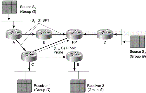
When encountering the situation shown in Figure 13-22, in which source traffic is flowing down the shared tree that is also receiving via the SPT, a special type of Prune is used to tell the RP to prune this source's traffic from the shared tree. This special prune is referred to as an (S, G) RP-bit Prune because it has the RP flag set in the Prune list entry. As you recall from the section "PIM Join/Prune Messages," the RP flag (also referred to as the RP-bit) indicates that this message is applicable to the shared tree and should be forwarded up the shared tree toward the RP. Setting this flag/bit in an (S1, G) Prune and sending it up the shared tree tells the routers along the shared tree to prune Source S1 multicast traffic from the shared tree.
Referring to Figure 13-23, Router C sends an (S1, G) RP-bit Prune up the shared tree toward the RP to prune S1 multicast traffic from the shared tree. After receiving this special prune, the RP updates its multicast forwarding state so that (S1, G) traffic is not forwarded down the link to Router C. However, because this link was the only interface on the shared tree that had (S1, G) traffic flowing down it, the RP no longer has any need for the (S1, G) traffic either.
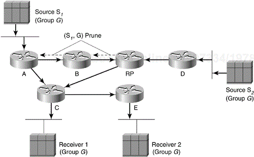
To shut off the now unneeded flow of (S1, G) traffic, the RP sends an (S1, G) Prune back toward Source S1. This Prune (shown by the dashed arrows in Figure 13-24) travels hop by hop through Router B until it reaches the first-hop router, Router A.
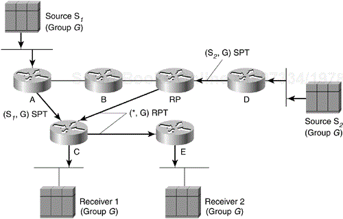
Figure 13-25 shows the result. Now, the (S1, G) SPT has been pruned, leaving only the link between Router A and Router C. Note that Router E is still receiving (S1, G) traffic from Router C (indicated by the solid arrow from C to E), although Router E is not aware that its upstream neighbor (Router C) has switched over to the SPT for Source S1.
Also note in Figure 13-25 that (S2, G) traffic is still flowing to the RP and down the shared tree to reach Receiver 1 and Receiver 2.
PIM elects a DR on each multi-access network (for example an Ethernet segment) using PIM Hello messages. In PIM-DM, the DR had meaning only if IGMPv1 was in use on the multi-access network because IGMPv1 does not have an IGMP Querier Election mechanism. In that case, the elected DR also functions as the IGMP Querier. However, in PIM-SM, the role of the DR is much more important, as you will see shortly.
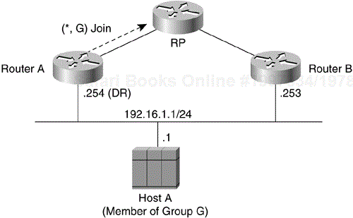
Consider the network example shown in Figure 13-26, in which two PIM-SM routers are connected to a common multi-access network with an active receiver for Group G. Because the Explicit Join model is used, only the DR (in this case, Router A) should send Joins to the RP to construct the shared tree for Group G. If both routers are permitted to send (*, G) Joins to the RP, parallel paths would be created and Host A would receive duplicate multicast traffic.
By the same token, if Host A begins to source multicast traffic to the group, the DR (Router A) is the router responsible for sending Register messages to the RP. Again, if both routers were permitted to send Register messages, the RP would receive duplicate multicast packets.
When more than one router is connected to a LAN segment, PIM-SM provides not only a method to elect the DR but also a way to detect the failure of the current DR. If the current DR (Router A) shown in Figure 13-26 were to fail, Router B would detect this situation when its neighbor adjacency with Router A timed out. Now, a new DR election takes place, and Router B becomes the active DR for the network.
In this case, Router B is already aware that an active receiver (Host A) exists on the network because it has been hearing IGMP Membership Reports from the host. As a result, Router B already has IGMP state for Group G on this interface, which would cause B to send a Join to the RP as soon as it was elected the new DR. This step re-establishes traffic flow down a new branch of the shared tree via Router B. Additionally, if Host A were sourcing traffic, Router B would initiate a new Register process immediately after receiving the next multicast packet from Host A. This action would trigger the RP to join the SPT to Host A via a new branch through Router B.
For PIM-SM to work properly, all routers within the PIM-SM domain must know the address of the RP. In small networks that use a single RP for all multicast groups, manually specifying the IP address of the RP in the configuration of each router might be possible. However, if the size of the network grows or if the RP changes frequently, manual configuration of every router becomes an administration nightmare. This problem is further compounded by the fact that different multicast groups use different RPs in other locations in the domain to either optimize the shared tree or spread the RP workload across multiple routers.
PIMv2 defines a Bootstrap mechanism that permits all PIM-SM routers within a domain to dynamically learn all Group-to-RP mappings and avoid the manual RP configuration problem. In addition, Cisco's PIM implementation has another mechanism, Auto-RP, which can accomplish the same thing. (Cisco's Auto-RP was developed before the PIMv2 specification was written so that existing Cisco PIM-SM networks could dynamically learn Group-to-RP mappings.)
Because PIM-SM uses the Explicit Join model, multicast traffic is better constrained to only those portions of the network where it is actually desired. Therefore, PIM-SM does not suffer from the inefficiencies found in flood-and-prune protocols such as DVMRP and PIM-DM. As a result, PIM-SM is better suited to multicast networks that have potential members at the end of WAN links.
In addition to the obvious advantages of the Explicit Join model, PIM-SM enables network engineers to use SPTs to reduce the network latency commonly associated with the use of shared trees. The decision to use or not use SPTs can be made on a group-by-group basis. For example, a low-rate, many-to-many multicast application (such as SDR) running over a star-topology network may not warrant the use of SPTs. In this case, the use of Infinity as the group's SPT-Threshold could force all group traffic to remain on the shared tree. This ability to control the use of SPTs gives network engineers greater control over the amount of state created in the routers in the network. Ultimately, the amount of state in the routers in the network is one of the primary factors that affects the scalability of any multicast routing protocol.
PIM-SM is arguably the best choice for an intra-domain multicast routing protocol for most general-purpose multicast networks. The possible exceptions are dedicated, special purpose networks that are designed to run very specific network applications under the complete control of the network administrators. (In these cases, PIM-SM may still be the best choice, although other protocols could possibly be made to work adequately given the tight controls that the network administrators have over the network and its applications.)
This chapter has presented an overview of the fundamentals of PIM-SM. The key points of PIM-SM are the use of an Explicit Join model to build shared trees and SPTs. In addition, because traffic only flows down the shared tree in traditional PIM-SM, there must be some way to get traffic from a source to the RP. This task is accomplished by the RP joining the SPT toward the source. However, first the RP must be made aware that the source exists, which requires the PIM Register mechanism. The final point, and possibly the most overlooked aspect of PIM-SM, is that routers with directly connected receivers usually immediately join the SPT to a newly detected source and bypass the RP.

