Edited by Christophe Paggen
This chapter describes the following three technologies that network designers can use to design switched LAN networks:
LAN switching (Ethernet, Fast Ethernet, and Gigabit Ethernet)
Virtual LANs (VLANs)
ATM switching (LAN Emulation, Multiprotocol over ATM)
Current scalable campus network-design practices will also be discussed.
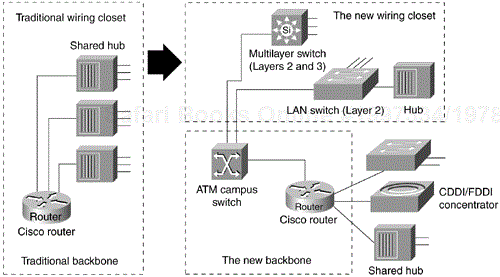
The LAN business is in constant evolution, driven by the desktop's need for more and more bandwidth. It is remarkable that even those working in the LAN domain for just more than a couple of years can actually refer to how things used to be "in the old days." A few years ago, the goal of a high-capacity LAN was to provide high aggregate capacity that could be shared among several devices. It was assumed that not all stations needed this capacity in a sustainable fashion; however, the total bandwidth was available on a time-share basis to whoever had to communicate. Shared LANs were very effective in providing a logical fully connected mesh topology without supporting the cost of several hundred point-to-point connections. A properly designed shared LAN maximized the probability of channel availability (that is, the sum of the stations'communication needs should be smaller than the channel's capacity). Huge increases in desktop computing power during the late 1980s meant that 10 Mbps could easily become the bottleneck in transmissions. Also, the constantly increasing number of devices per segment continued to contribute to the overall channel utilization. To improve user performance, network administrators began to segment shared LANs using bridges. LAN bridges have been available since 1984, but their internal bridging capacity remained the limiting factor, and wire-speed bridging was a luxury. With the progress made in the field of semiconductors in the 1990s, application-specific integrated circuits (ASICs) started to emerge, making it possible to build multiport LAN bridges capable of forwarding frames at wire rate. The bridges were launched on the market as switches. Network designers were prompted to replace their legacy hubs in the wiring closets with switches, as shown in Figure 12-1.
This strategy enabled network managers to protect their existing wiring investments and boost network performance with dedicated bandwidth to the desktop for each user. Coinciding with the wiring-closet evolution is a similar trend in the network backbone. Today, the role of Fast Ethernet, ATM (Asynchronous Transfer Mode), and lately Gigabit Ethernet is constantly increasing. Several protocols have now been standardized, such as LAN Emulation (LANE), 802.1q/p, and 802.3z and 802.3ab (1000BaseTX). Network designers are collapsing their router backbones with high-performance multilayer switches, switching routers, or ATM switches, to offer the greater backbone bandwidth required by high-throughput data services.
With the advent of such technologies as Layer 2 switching, Layer 3 and 4 switching, and VLANs, building campus LANs is becoming more complex than in the past. Today, the following four technologies are required to build successful campus networks:
LAN switching technologies
Ethernet, Fast Ethernet, and Gigabit Ethernet switching provide Layer 2 switching and offer broadcast domain segmentation using VLANs. This is the base fabric of the network. Token Ring switching offers the same functionality as Ethernet switching but uses 16 Mbps Token Ring technology. You can use a Token Ring switch as either a transparent bridge or source-route bridge. Ethernet has become a more popular medium than Token Ring today, however, and is preferred over the legacy bus technology.
Link aggregation for higher bandwidth
The aggregation of individual Fast Ethernet links makes it possible to create 800-Mbps channels. Gigabit Ethernet interfaces can also be bundled to provide multigigabit pipes that rival and even surpass the highest speeds offered by today's ATM solutions. These channels are treated as a single logical link from a switch's perspective, thus providing seamless integration with the Spanning-Tree Protocol.
ATM switching technologies
ATM switching offers high-speed switching technology for voice, video, and data. Aggregated bandwidths of up to OC-48 speeds (roughly 2.480 Mbps) are emerging today, while OC-12 (roughly 620 Mbps) interfaces are a reality in many networks. ATM operation is almost similar to LAN switching technologies for data operations.
Routing technologies
Routing is a key technology for connecting LANs in a campus network. Many of today's routers can achieve wire-speed routing; therefore, they are frequently referred to as Layer 3 or 4 switching routers. Layer 3 (or 4) switching is nothing more than regular routing highly optimized for speed.
Note
Switched LAN networks are also referred to as campus LANs.
Most network designers have integrated switching devices into their existing shared-media networks to achieve the following goals:
Increase the bandwidth available to each user, thereby alleviating congestion in their shared-media networks. 10/100-Mbps links to the desktop are common today. Some vendors have already started to manufacture Gigabit Ethernet NICs.
Employ the manageability of VLANs along with the flexibility and scalability of routing. This, combined with the use of Dynamic Host Resolution Protocol (DHRP) servers, can reduce the cost of moves, adds, and changes.
Deploy emerging multimedia applications across different switching platforms and technologies, making them available to a variety of users. This type of software makes extensive use of IP multicast. An example of such an application is the IP/TV software.
Provide a smooth evolution path to high-performance switching solutions, such as Gigabit Ethernet and high-speed ATM.
Segmenting shared-media LANs divides the users into two or more separate LAN segments, reducing the number of users contending for bandwidth. LAN switching technology, which builds on this trend, employs microsegmentation, which further segments the LAN to fewer users and ultimately to a single user with a dedicated LAN segment. Each switch port provides a dedicated 10/100/1000-Mbps Ethernet segment or a dedicated 4/16-Mbps Token Ring segment for legacy environments.
Segments (also referred to as VLANs) are interconnected by networking devices that enable communication between LANs while blocking other types of traffic, typically routers. Switches have the intelligence to monitor traffic and build address tables based on source MAC addresses, which then allows them to forward packets directly to specific ports. Switches also usually provide nonblocking service, which allows multiple conversations (traffic between two ports) to occur simultaneously. A switch architecture is said to be nonblocking when its switching fabric's bandwidth exceeds the aggregate bandwidth of all its ports (that is, a 12-Gbps backplane for 96 10/100-Mbps ports).
Switching technology has become the preferred solution for improving LAN traffic for the following reasons:
Unlike hubs and repeaters, switches allow multiple data streams to pass simultaneously (a switch is equal to multiple independent two-port bridges) and independently.
Switches have the capability through microsegmentation to support the increased speed and bandwidth requirements of emerging technologies (that is, a VLAN is a broadcast domain).
Switches deliver dedicated bandwidth to users through high-density group-switched and switched 10/100 fiber- or copper-based Ethernet, Fast EtherChannel, Gigabit Ethernet, Gigabit EtherChannel and ATM LAN Emulation (LANE), or Multiprotocol over ATM (MPOA).
To be successful, a switched network solution should accomplish the following:
Leverage strategic investments in the existing communications infrastructure while increasing available bandwidth (for example, reutilization of the existing wiring scheme).
Reduce the costs of managing network operations.
Offer options to support multimedia applications and other high-demand traffic across a variety of platforms (for example, IGMP snooping). This implies the support of quality of service (QoS) features to provide preferential treatment to certain patterns of traffic (for example, differentiation based on IP precedence or 802.1q priority).
Provide scalability, traffic control, and security at least as well as or better than today's router-based networks (for example, protocol filtering and port security).
Provide support for the embedded remote monitoring (RMON) agent.
The key to achieving these benefits is to understand the role of the networking software infrastructure within the switched network. Within today's networks, routers allow for the interconnection of disparate LAN and WAN technologies, while also implementing security filters and logical firewalls. It is these capabilities that have allowed current networks to scale globally while remaining stable and robust. Routers also limit the radiation scope of broadcasts—that is, an all-ones broadcast does not cross a router unless specifically instructed to do so.
As networks evolve toward switched networks, similar logical networking capabilities are required for stability and scalability. Although LAN and ATM switches provide great performance improvements, they also raise new networking challenges. Switched networks must integrate with existing LAN and WAN networks, as well as with future multiservice networks capable of simultaneously carrying voice and data traffic.
A true switched network, therefore, is more than a collection of boxes. Rather, it consists of a system of devices integrated and supported by an intelligent networking software infrastructure. What used to be centralized within routers is now becoming available on high-end multilayer LAN switches. With the advent of switched networks, the intelligence is often dispersed throughout the network, reflecting the decentralized nature of switching systems. The need for a networking infrastructure, however, remains.
The following three basic components make up a switched network:
Physical switching platforms
A common software infrastructure
Network-management tools and applications
Cisco provides network designers with a complete, end-to-end solution for implementing and managing scalable, robust, switched networks.
The first component of the switched networking model is the physical switching platform. This can be an ATM switch, a multilayer LAN switch, or a switching router.
Cisco Systems'Enterprise Multiservice Asynchronous Transfer Mode (ATM) Switch family offers mid-range ATM switches for ATM workgroups and campus backbones, metropolitan-area networks (MANs), and alternative service provider backbones. This series of switches spans from 5 to 40 Gbps in performance. The Enterprise Multiservice ATM Switches provide services optimized for both cell- and packet-based applications, including support for all ATM traffic classes and up to OC-48 switching capabilities. As the family expands, new members of the product family can take advantage of the existing set of carrier adapter modules (CAMs), port adapter modules (PAMs), and switch software, or use upgraded CAMs and PAMs specifically designed for those products. This forward compatibility protects existing equipment and software investments while facilitating network evolution.
For campus networks, the product family currently includes the following:
LightStream 1010 (LS1010)—. A 5-Gbps fully nonblocking modular ATM switch supporting a wide range of interfaces ranging from T1/E1 speeds up to 622-Mbps OC-12c
Catalyst 8510 (Cat8510)—. An L2/L3/ATM 10-Gbps wire-speed nonblocking modular switch with up to OC-12c interface switching speed currently, and support for both Fast and Gigabit Ethernet
Catalyst 8540 (Cat8540)—. An L2/L3/ATM 40-Gbps modular switch with up to OC-12 switching speed currently, support for both Fast and Gigabit Ethernet, and optional switching fabric and CPU redundancy
Just as there are routers and LAN switches available at various price/performance points with different levels of functionality, ATM switches can be segmented into the following four distinct types that reflect the needs of particular applications and markets:
Workgroup ATM switches
Campus ATM switches
Enterprise ATM switches
Multiservice ATM switches
Workgroup ATM switches are optimized for deploying ATM to the desktop over low-cost ATM desktop interfaces, with ATM signaling interoperability for ATM adapters and QoS support for multimedia applications.
Campus ATM switches are generally used for small-scale ATM backbones (for example, to link ATM routers or LAN switches). This use of ATM switches can alleviate current backbone congestion while enabling the deployment of such services as VLANs. Campus switches need to support a wide variety of both local backbone and WAN types but also need to be price/performance optimized for the local backbone function. In this class of switches, ATM routing capabilities that allow multiple switches to be tied together are very important. Congestion-control mechanisms for optimizing backbone performance are also important.
Enterprise and Multiservice ATM switches are sophisticated devices designed to form the core backbones of large enterprise networks. They are intended to complement the role played by today's high-end multiprotocol routers. Enterprise ATM switches, much like campus ATM switches, are used to interconnect workgroup ATM switches and other ATM-connected devices, such as LAN switches. They provide cell and frame services, along with advanced QoS and dynamic routing features. Enterprise-class switches, however, cannot only act as ATM backbones but can also serve as the single point of integration for all the disparate services and technology found in enterprise backbones today (such as voice, video, and data). By integrating all these services onto a common platform and a common ATM transport infrastructure, network designers can gain greater manageability while eliminating the need for multiple overlay networks.
A LAN switch is a device that typically consists of many ports that connect LAN segments (typically 10/100-Mbps Ethernet) and several high-speed ports (such as 100-Mbps Fast Ethernet, OC-12/48 ATM, or Gigabit Ethernet). These high-speed ports, in turn, connect the LAN switch to other devices in the network. The three main categories of LAN switches are as follows:
Wiring-closet switch—. A device to provide host access at the edge of the network (for example, the Catalyst 2900XL, the Catalyst 400 series of switches, or even the Catalyst 5x00 series)
Multilayer switch—. A Layer 2, 3, or 4 device that provides various interfaces, high port densities, and a wide range of functions that make it suitable for the distribution of core layers of the network (for example, the Catalyst 5500 or 6000 family of switches)
Switching router—. A Layer 2, 3, or 4 device primarily focused at the core layer of the network, providing wire-speed multiservice switching on all its interfaces (for example, the Catalyst 8500)
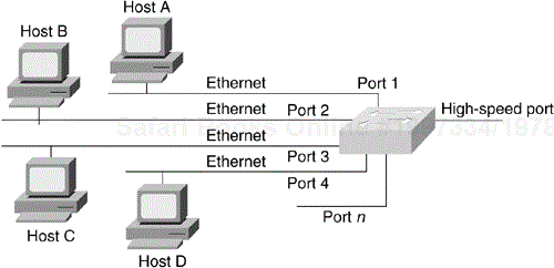
A LAN switch has dedicated bandwidth per port, and each port represents a different segment. For best performance, network designers often assign just one host to a port, giving that host dedicated bandwidth of 10 Mbps, 100 Mbps, or even 1 Gbps, as shown in Figure 12-2, or 16 Mbps for legacy Token Ring networks.
When a LAN switch first starts up, and as the devices connected to it request services from other devices, the switch builds a table that associates the source MAC address of each local device with the port number on which that device was heard. That way, when Host A on Port 1 needs to transmit to Host B on Port 2, the LAN switch forwards frames from Port 1 to Port 2, thus sparing other hosts on Port 3 from responding to frames destined for Host B. If Host C needs to send data to Host D at the same time that Host A sends data to Host B, it can do so because the LAN switch can forward frames from Port 3 to Port 4 at the same time it forwards frames from Port 1 to Port 2.
Whenever a device connected to the LAN switch sends a packet to an address that is not in the LAN switch's table (this table is sometimes referred to as the CAM table), or whenever the device sends a broadcast or multicast packet, the LAN switch sends the packet out all ports (except for the port from which the packet originated)—a technique known as flooding Several techniques exist to constrain the flooding of multicast traffic to certain ports only, including the Cisco Group Management Protocol (CGMP) and the Internet Group Management Protocol (IGMP) snooping for Layer 3–capable switches. These protocols act on multicast packets only, not broadcast. Another feature called broadcast suppression can help alleviate the adverse effects of broadcast storms.
Because they work like traditional "transparent" bridges, LAN switches dissolve previously well-defined workgroup or department boundaries. A network built and designed only with LAN switches appears as a flat network topology consisting of a single broadcast domain. Consequently, these networks are liable to suffer the problems inherent in flat (or bridged) networks—that is, they do not scale well. Note, however, that LAN switches that support VLANs are more scalable than traditional bridges. The scalability problem is primarily associated with a very useful protocol found in almost every redundant Layer 2 network: the IEEE 802.1d Spanning-Tree Protocol.
Beyond private networks, ATM platforms will also be widely deployed by service providers both as customer premises equipment (CPE) and within public networks. Such equipment will be used to support multiple MAN and WAN services—for example, Frame Relay switching, LAN interconnect, or public ATM services—on a common ATM infrastructure. Enterprise ATM switches will often be used in these public network applications because of their emphasis on high availability and redundancy, and their support of multiple interfaces.
In addition to LAN switches and ATM switches, network designers use routers as one of the key components in a switched network infrastructure. While LAN switches are being added to wiring closets to increase bandwidth and to reduce congestion in existing shared-media hubs, high-speed backbone technologies such as Gigabit Ethernet switching (or ATM switching) are being deployed in the backbone. Within a switched network, routing platforms allow for the interconnection of disparate LAN and WAN technologies while also implementing broadcast filters and logical firewalls. In general, if you need advanced networking services, such as broadcast firewalling and communication between dissimilar LANs, routers are necessary. Also, switching routers play a very significant role in today's campus networks: They limit the scope of VLANs and, more particularly, limit the scope of the spanning-tree domains. With the creation of centralized server farms, traffic patterns now demand wire-rate switching routers, and various techniques are available to achieve this (for example, Multilayer LAN Switching [MLS], Cisco Express Forwarding [CEF], and Multiprocol over ATM [MPOA]). Routers (or switching routers, or multilayer switches) play a very important role in the scalability of today's campus networks. This trend is making flat networks implemented by campus-wide VLANs disappear.
The second level of a switched networking model is a common software infrastructure. The function of this software infrastructure is to unify the variety of physical switching platforms: multilayer LAN switches, ATM switches, and multiprotocol routers. Specifically, the software infrastructure should perform the following tasks:
Monitor the logical topology of the network
Logically route and reroute the traffic
Manage and control sensitive traffic
Provide firewalls, gateways, filtering, and protocol translation
Cisco offers network designers Cisco Internetwork Operating System (Cisco IOS) switching software. This subset of the Cisco IOS software is optimized for switching and provides the unifying element to Cisco's line of switching platforms in a switched network. The Cisco IOS software is found on stand-alone routers, router modules for shared-media hubs, multilayer switches, multiservice WAN access switches, LAN switches, ATM switches, and ATM-capable PBXs. It provides optional levels of routing and switching across a switched network in addition to new capabilities, such as VLANs trunking, ATM networking software services, wire-speed multilayer switching, extensions to support new networked multimedia applications (IP multicast and so on), traffic management and analysis tools, and many other features.
A VLAN typically consists of several end systems, either hosts or network equipment (such as switches and routers), all of which are members of a single logical broadcast domain. A VLAN does not have physical proximity constraints for the broadcast domain. A VLAN is supported on various pieces of network equipment (for example, LAN switches) that support VLAN trunking protocols between them. Each VLAN supports a separate spanning tree (IEEE 802.1d), allowing various logical topologies with only a single physical network (that is, VLAN load balancing on equal-cost trunks and so forth). It is a common practice to implement VLANs so that they map to a Layer 3 protocol subnet.
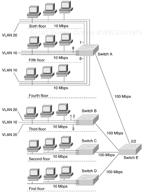
First-generation VLANs are based on various OSI Layer 2 multiplexing mechanisms— such as IEEE 802.10 for FDDI interfaces, LAN Emulation (LANE) on ATM links, Inter-Switch Link (ISL), or IEEE 802.1q on Ethernet—that allow the formation of multiple, disjointed, overlaid broadcast groups on a single network infrastructure. (That is, it is possible to carry multiple VLANs across a single physical interface, also known as a trunk.) Figure 12-3 shows an example of a switched LAN network that uses campus-wide VLANs (a concept that started to emerge in 1996). Layer 2 of the OSI reference model provides reliable transit of data across a physical link. The data link layer is concerned with physical addressing, network topology, line discipline, error notification, ordered delivery frames, and flow control. The IEEE has divided this layer into two sublayers: the MAC sublayer and the LLC sublayer, sometimes simply called the link layer.
In Figure 12-3, 10/100-Mbps Ethernet connects the hosts on each floor to Switches A, B, C, and D. 100-Mbps Fast Ethernet or Gigabit Ethernet connects these to Switch E. VLAN 10 consists of those hosts on Ports 6 and 8 of Switch A and Port 2 on Switch B. VLAN 20 consists of those hosts that are on Port 1 of Switch A and Ports 1 and 3 of Switch B.
VLANs can be used to group a set of related users, regardless of their physical connectivity. They can be located across a campus environment or even across geographically dispersed locations.
Although deploying campus-wide VLANs was a very common practice a year ago, it is a design technique that is quickly becoming obsolete, mostly because this model does not scale well. The scalability problem is partly inherent to the Spanning-Tree Protocol (STP), a protocol used to break logical loops at Layer 2 of the OSI model. Because there is no Time To Live (TTL) field in the Layer 2 header, it is possible to have packets looping in the network for an infinite amount of time! Contrary to popular belief, there is no need for a broadcast packet to create an infinite loop—it is absolutely possible to have a unicast storm in a Layer 2 network. Even though STP is supposed to break these logical loops, it puts a burden on the switches'CPU. When the STP operation becomes impaired for any reason (lack of CPU resources and so forth), it is possible to suffer from a network meltdown. The following are characteristics of the STP broadcast domain:
Redundant links are blocked and carry no data traffic.
Suboptimal paths exist between different points.
The Spanning-Tree Protocol convergence typically takes 50 seconds (2 × Forward_Delay + Max Age = 2 × 15 + 20 = 50). Although the minimum IEEE values allow for a minimum convergence time of 14 seconds (2 × 4 + 6), it is certainly not recommended to apply these minimal values in most networks.
Broadcast traffic within the Layer 2 domain interrupts every host.
Broadcast or unicast storms with the Layer 2 domain affect the whole domain. A local problem quickly becomes a global issue.
Isolating the problem is cumbersome and time-consuming.
Network security offered at Layer 2 of the OSI model is limited.
Without a router, hosts in one VLAN cannot communicate with hosts in another VLAN. Compared with STP, routing protocols have the following characteristics:
Load balancing across many equal-cost paths (up to six on certain Cisco platforms)
Optimal or lower-cost paths between networks
Faster convergence than STP with intelligent protocols such as EIGRP, IS-IS, and OSPF
Summarized (and therefore scalable) reachability information
Isolating a problem at Layer 3 is easier than at Layer 2.
The third and last component of a switched networking model consists of network-management tools and applications. As switching is integrated throughout the network, network management becomes crucial at both the workgroup and backbone levels.
Managing a switch-based network requires a radically different approach than managing traditional hub- and router-based LANs.
As part of designing a switched network, network designers must ensure that their design takes into account network-management applications needed to monitor, configure, plan, and analyze switched network devices and services. Cisco offers such tools for emerging switched networks.
Now that the various components of switched campus networks have been introduced, several campus network-design possibilities will be examined and discussed. Scalability factors, as well as migrations from legacy environments to highly efficient switched networks, will be thoroughly analyzed too.
Figure 12-4 shows a campus with the traditional hub-and-router design. The access layer devices are hubs that act as Layer 1 repeaters. The distribution layer consists of routers. The core layer contains FDDI concentrators or other hubs that act as Layer 1 repeaters. Routers in the distribution layer provide broadcast control and segmentation. Each wiring-closet hub corresponds to a logical network or subnet and homes to a router port. Alternatively, several hubs can be cascaded or bridged together to form one logical subnet or network.
The hub-and-router model is scalable because of the advantages of intelligent routing protocols such as OSPF and Enhanced IGRP. The distribution layer is the demarcation between networks in the access layer and networks in the core.
Distribution layer routers provide segmentation and terminate collision domains as well as broadcast domains. The model is consistent and deterministic, which simplifies troubleshooting and administration. This model also maps well to all the network protocols, such as Novell IPX, AppleTalk, DECnet, and TCP/IP.
The hub-and-router model is straightforward to configure and maintain because of its modularity. Each router within the distribution layer is programmed with the same features. Common configuration elements can be cut and pasted across the layer. Because each router is programmed the same way, its behavior is predictable, which makes troubleshooting easier.
Layer 3 packet-switching load and middleware services are shared among all the routers in the distribution layer.
The traditional hub-and-router campus model can be upgraded as performance demands increase. The shared media in the access layer and core can be upgraded to Layer 2 switching, and the distribution layer can be upgraded to Layer 3 switching with multilayer switching. Upgrading shared Layer 1 media to switched Layer 2 media does not change the network addressing, the logical design, or the programming of the routers.
Figure 12-5 shows a conventional legacy campus-wide VLAN design. Layer 2 switching is used in the access, distribution, and core layers. Four workgroups represented by the colors blue, red, purple, and green are distributed across several access layer switches. Connectivity between workgroups is by Router X, which connects to all four VLANs. Layer 3 switching and services are concentrated at Router X. Enterprise servers are shown behind the router on different logical networks indicated by the lines.
The various VLAN connections to Router X could be replaced with an ISL trunk. In either case, Router X is typically referred to as a "router on a stick" or a "one-armed router." More routers can be used to distribute the load, and each router attaches to several or all VLANs. Traffic between workgroups must traverse the campus in the source VLAN to a port on the gateway router, and then back out into the destination VLAN.
Figure 12-6 shows an updated version of the campus-wide VLAN model that takes advantage of multilayer switching. The switch marked X is a Catalyst 5000 family multilayer switch. The one-armed router is replaced by an RSM and the hardware-based Layer 3 switching of the NetFlow Feature Card. Enterprise servers in the server farm may be attached by Fast Ethernet at 100 Mbps, or by Fast EtherChannel to increase the bandwidth to 200-Mbps FDX or 400-Mbps FDX.
The campus-wide VLAN model is highly dependent on the 80/20 rule. If 80% of the traffic is within a workgroup, 80% of the packets are switched at Layer 2 from client to server. If 90% of the traffic goes to the enterprise servers in the server farm, however, 90% of the packets are switched by the one-armed router. The scalability and performance of the VLAN model are limited by the characteristics of STP. Each VLAN is equivalent to a flat bridged network.
The campus-wide VLAN model provides the flexibility to have statically configured end stations move to a different floor or building within the campus. Cisco's VLAN Membership Policy Server (VMPS) and the VLAN Trunking Protocol (VTP) make this possible. A mobile user plugs a laptop PC into a LAN port in another building. The local Catalyst switch sends a query to the VMPS to determine the access policy and VLAN membership for the user. Then the Catalyst switch adds the user's port to the appropriate VLAN.
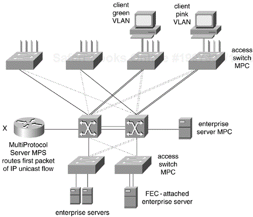
Multiprotocol over ATM (MPOA) adds Layer 3 cut-through switching to ATM LANE. The ATM infrastructure is the same as in ATM LANE. The LECS and the LES/BUS for each ELAN are configured the usual way. Figure 12-7 shows the elements of a small MPOA campus design.
With MPOA, the new elements are the multiprotocol client (MPC) hardware and software on the access switches as well as the multiprotocol server (MPS), which is implemented in software on Router X. When the client in the pink VLAN talks to an enterprise server in the server farm, the first packet goes from the MPC in the access switch to the MPS using LANE. The MPS forwards the packet to the destination MPC using LANE. Then the MPS tells the two MPCs to establish a direct switched virtual circuit (SVC) path between the green subnet and the server farm subnet.
With MPOA, IP unicast packets take the cut-through SVC as indicated. Multicast packets, however, are sent to the BUS to be flooded in the originating ELAN. Then Router X copies the multicast to the BUS in every ELAN that needs to receive the packet as determined by multicast routing. In turn, each BUS floods the packet again within each destination ELAN.
Packets of protocols other than IP always proceed LANE to router to LANE without establishing a direct cut-through SVC. MPOA design must consider the amount of broadcast, multicast, and non-IP traffic in relation to the performance of the router. MPOA should be considered for networks with predominately IP unicast traffic and ATM trunks to the wiring-closet switch.
One of the key concepts in building highly efficient and scalable campus networks is to think of the network as a big modular puzzle—a puzzle where it is possible to easily add new pieces—a piece being either a new building, a new group of users, or a server farm, for example. To achieve this, layers need to be introduced into the picture. This is what the multilayer model addresses.
The conventional wisdom of the 80/20 rule underlies the traditional design models discussed in the preceding section. With the campus-wide VLAN model, the logical workgroup is dispersed across the campus but is still organized such that 80% of traffic is contained within the VLAN. The remaining 20% of traffic leaves the network or subnet through a router.
The traditional 80/20 traffic model arose because each department or workgroup had a local server on the LAN. The local server was used as a file server, logon server, and application server for the workgroup. The 80/20 traffic pattern has been changing rapidly with the rise of corporate intranets and applications that rely on distributed IP services. Many new and existing applications are moving to distributed World Wide Web (WWW)–based data storage and retrieval. The traffic pattern is moving toward what is now referred to as the 20/80 model. In the 2 0/80 model, only 20% of traffic is local to the workgroup LAN, and 80% of the traffic leaves.
The performance of multilayer switching matches the requirements of the new 20/80 traffic model. The two components of multilayer switching on the Catalyst 5000 family are the RSM and the NetFlow Feature Card. The RSM is a Cisco IOS-based multiprotocol router on a card. It has performance and features similar to a Cisco 7500 RSP/2 router. The NetFlow Feature Card (NFFC/NFFC-2) is a daughter-card upgrade to the Supervisor Engine of the Catalyst 5000 family of switches. It performs both Layer 3 for IP, IP Multicast, or IPX and Layer 2 switching in hardware with specialized ASICs. It is important to note that there is no performance penalty associated with Layer 3 switching versus Layer 2 switching with the NetFlow Feature Card. An alternative is the more powerful Catalyst 6000 family and its multilayer switching module (MSM), based on the Catalyst 8510 SRP, with performance figures in the neighborhood of 6 million packets per second for IP and IPX. For even more performance, the Catalyst 6000's future Multiprotocol Switching Feature Card (MSFC) can be used, boosting the performance to 15 million packets per second for IP and IPX.
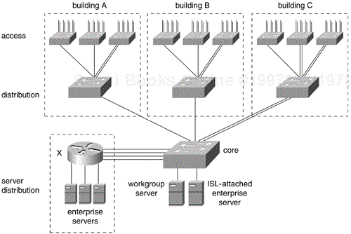
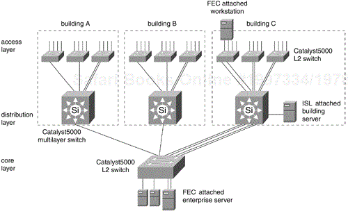
Figure 12-8 illustrates a simple multilayer campus network design. The campus consists of three buildings, A, B, and C, connected by a backbone called the core. The distribution layer consists of Catalyst 5000 or 6000 family multilayer switches. The multilayer design takes advantage of the Layer 2 switching performance and features of the Catalyst family switches in the access layer and backbone and uses multilayer switching in the distribution layer. The multilayer model preserves the existing logical network design and addressing, as in the traditional hub-and-router model. Access layer subnets terminate at the distribution layer. From the other side, backbone subnets also terminate at the distribution layer. So the multilayer model does not consist of campus-wide VLANs but does take advantage of VLAN trunking, as discussed later.
Because Layer 3 switching is used in the distribution layer of the multilayer model, this is where many of the characteristic advantages of routing apply. The distribution layer forms a broadcast boundary so that broadcasts don't pass from a building to the backbone or vice versa. Value-added features of the Cisco IOS software apply at the distribution layer. The distribution layer switches cache information about Novell servers, for example, and respond to Get Nearest Server queries from Novell clients in the building. Another example is forwarding Dynamic Host Configuration Protocol (DHCP) messages from mobile IP workstations to a DHCP server.
Another Cisco IOS feature implemented at the multilayer switches in the distribution layer is called Local-Area Mobility (LAM). LAM is valuable for campus intranets that have not deployed DHCP services and permits workstations with statically configured IP addresses and gateways to move throughout the campus. LAM works by propagating the address of the mobile hosts (via host or /32 routes) out into the Layer 3 routing table.
Actually, hundreds of valuable Cisco IOS features improve the stability, scalability, and manageability of enterprise networks. These features apply to all the protocols found in the campus, including DECnet, AppleTalk, IBM SNA, Novell IPX, TCP/IP, and many others. One characteristic shared by most of these features is that they are "out of the box." Out-of-the-box features apply to the functioning of the network as a whole. They are in contrast with "inside-the-box" features, such as port density or performance, that apply to a single box rather than to the network as a whole. Inside-the-box features have little to do with the stability, scalability, or manageability of enterprise networks.
The greatest strengths of the multilayer model arise from its hierarchical and modular nature. It is hierarchical because the layers are clearly defined and specialized. It is modular because every part within a layer performs the same logical function. One key advantage of modular design is that different technologies can be deployed with no impact on the logical structure of the model. Token Ring can be replaced by Ethernet, for example. FDDI can be replaced by Switched Fast Ethernet. Hubs can be replaced by Layer 2 switches. Fast Ethernet can be substituted for ATM LANE. ATM LANE can be substituted for Gigabit Ethernet, and so on. So modularity makes both migration and integration of legacy technologies much easier.
Another key advantage of modular design is that each device within a layer is programmed the same way and performs the same job, making configuration much easier. Troubleshooting is also easier, because the whole design is highly deterministic in terms of performance, path determination, and failure recovery.
In the access layer, a subnet corresponds to a VLAN. A VLAN may map to a single Layer 2 switch, or it may appear at several switches. Conversely, one or more VLANs may appear at a given Layer 2 switch. If Catalyst 4000, 5000, or 6000 family switches are used in the access layer, VLAN trunking (ISL or 802.1q) provides flexible allocation of networks and subnets across more than one switch. Examples later in this chapter show two VLANs per switch, to illustrate how to use VLAN trunking to achieve load balancing and fast failure recovery between the access layer and the distribution layer.
In its simplest form, the core layer is a single logical network or VLAN. The examples in this chapter show the core layer as a simple switched Layer 2 infrastructure with no loops. It is advantageous to avoid spanning-tree loops in the core. This discussion focuses on taking advantage of the load balancing and fast convergence of Layer 3 routing protocols such as OSPF and Enhanced IGRP to handle path determination and failure recovery across the backbone. Therefore, all the path determination and failure recovery is handled at the distribution layer in the multilayer model.
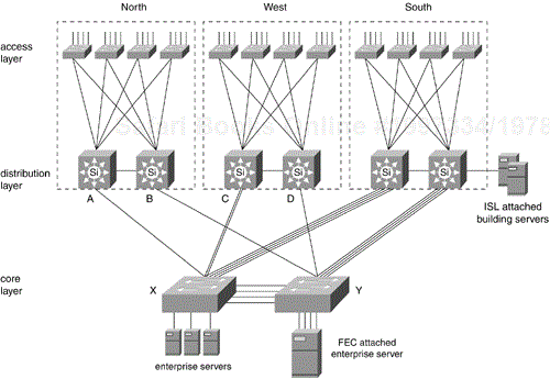
A distribution layer switch in Figure 12-8 represents a point of failure at the building level. One thousand users in Building A could lose their connections to the backbone in the event of a power failure. If a link from a wiring-closet switch to the distribution layer switch is disconnected, 100 users on a floor could lose their connections to the backbone. Figure 12-9 shows a multilayer design that addresses these issues.
Multilayer Switches A and B provide redundant connectivity to domain North. Redundant links from each access layer switch connect to distribution layer switches A and B. Redundancy in the backbone is achieved by installing two or more Catalyst switches in the core. Redundant links from the distribution layer provide failover as well as load balancing over multiple paths across the backbone.
Redundant links connect access layer switches to a pair of Catalyst multilayer switches in the distribution layer. Fast failover at Layer 3 is achieved with Cisco's Hot Standby Router Protocol. The two distribution layer switches cooperate to provide HSRP gateway routers for all the IP hosts in the building. Fast failover at Layer 2 is achieved by Cisco's UplinkFast feature. UplinkFast is a convergence algorithm that achieves link failover from the forwarding link to the backup link in about three seconds.
Load balancing across the core is achieved by intelligent Layer 3 routing protocols implemented in the Cisco IOS software. In this picture, there are four equal-cost paths between any two buildings. In Figure 12-9, the four paths from domain North to domain West are AXC, AXYD, BYD, and BYXC. These four Layer 2 paths are considered equal by Layer 3 routing protocols. Note that all paths from domains North, West, and South to the backbone are single, logical hops. The Cisco IOS software supports load balancing over up to six equal-cost paths for IP (this is currently not possible on the Catalyst 8500 family of switching routers; two equal-cost paths are supported, however), and over many paths for other protocols.
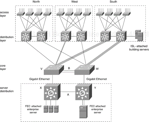
Figure 12-10 shows the redundant multilayer model with an enterprise server farm. The server farm is implemented as a modular building block using multilayer switching. The Gigabit Ethernet trunk labeled A carries the server-to-server traffic. The Fast EtherChannel trunk labeled B carries the backbone traffic. All server-to-server traffic is kept off the backbone, which has both security and performance advantages. The enterprise servers have fast HSRP redundancy between the multilayer switches X and Y. Access policy to the server farm can be controlled by access lists on X and Y. In Figure 12-10, the Layer 2 core switches V and W are shown separate from server distribution switches X and Y for clarity. In a network of this size, V and W would collapse into X and Y.
Putting servers in a server farm also avoids problems associated with IP redirect and selecting the best gateway router when servers are directly attached to the backbone subnet, as shown in Figure 12-9. In particular, HSRP would not be used for the enterprise servers in Figure 12-9; they would use proxy Address Resolution Protocol (ARP), Internet Router Discovery Protocol (IRDP), Gateway Discovery Protocol (GDP), or Routing Information Protocol (RIP) snooping to populate their routing tables.
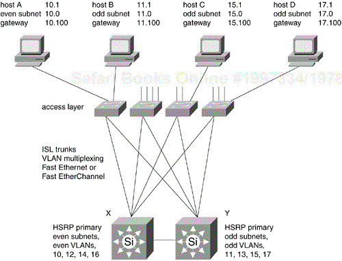
Figure 12-11 shows HSRP operating between two distribution layer switches. Host systems connect at a switch port in the access layer. The even-numbered subnets map to even-numbered VLANs, and the odd-numbered subnets map to odd-numbered VLANs. The HSRP primary for the even-numbered subnets is distribution layer Switch X, and the HSRP primary for the odd-numbered subnets is Switch Y. The HSRP backup for even-numbered subnets is Switch Y, and the HSRP backup for odd-numbered subnets is Switch X. The convention followed here is that every HSRP gateway router always has host address 100—so the HSRP gateway for subnet 15.0 is 15.100. If gateway 15.100 loses power or is disconnected, Switch X assumes the address 15.100 as well as the HSRP MAC address within about two seconds.
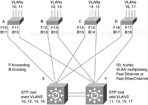
Figure 12-12 shows load balancing between the access layer and the distribution layer using Cisco's ISL (or IEEE 802.1q) VLAN trunking protocol. In this example, VLANs 10 and 11 are allocated to access layer Switch A, and VLANs 12 and 13 to Switch B. Each access layer switch has two trunks to the distribution layer. The STP puts redundant links in blocking mode as shown. Load distribution is achieved by making one ----trunk the active forwarding path for even-numbered VLANs and the other trunk the active forwarding path for odd-numbered VLANs.
On Switch A, the left trunk is labeled F10, which means that it is the forwarding path for VLAN 10. The right trunk is labeled F11, which means that it is the forwarding path for VLAN 11. The left trunk is also labeled B11, which means that it is the blocking path for VLAN 11, and the right trunk is B10, which means that it is the blocking for VLAN 10. This is accomplished by making X the root for even VLANs and Y the root for odd VLANs.
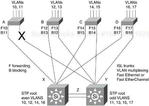
Figure 12-13 shows Figure 12-12 after a link failure, which is indicated by the big X. UplinkFast changes the left trunk on Switch A to be the active forwarding path for VLAN 11. Traffic is switched across Fast EtherChannel Trunk Z if required. Trunk Z is the Layer 2 backup path for all VLANs in the domain and also carries some of the return traffic that is load-balanced between Switch X and Switch Y. With conventional STP, convergence would take 40 to 50 seconds. With UplinkFast, failover takes about three seconds.
Ethernet trunk capacity in the multilayer model can be scaled in several ways. Ethernet can be migrated to Fast Ethernet. Fast Ethernet can be migrated to Fast EtherChannel or Gigabit Ethernet or Gigabit EtherChannel. Access layer switches can be partitioned into multiple VLANs with multiple trunks. VLAN multiplexing with ISL or 802.1q can be used in combination with the different trunks.
Fast EtherChannel combines up to eight Fast Ethernet links into a single high-capacity trunk. Fast EtherChannel is supported by the Cisco 7500 and 8500 family of routers. It is supported on Catalyst 4000, 5000, and 6000 switches. Fast EtherChannel support has been announced by several partners, including Adaptec, Auspex, Compaq, Hewlett-Packard, Intel, Sun Microsystems, and Znyx. With Fast EtherChannel trunking, a high-capacity server can be connected to the core backbone at 400-Mbps FDX for 800-Mbps total throughput. High-end Cisco routers also support Gigabit EtherChannel, and several vendors have also announced Gigabit NICs.
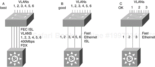
Figure 12-14 shows three ways to scale bandwidth between an access layer switch and a distribution layer switch. On the configuration labeled "A Best," all VLANs are combined over Fast EtherChannel with ISL or 802.1q. In the middle configuration, labeled "B Good," a combination of segmentation and ISL trunking is used. On the configuration labeled "C OK," simple segmentation is used.
You should use model A if possible, because Fast EtherChannel provides more efficient bandwidth utilization by multiplexing traffic from multiple VLANs over one trunk. If a Fast EtherChannel line card is not available, use model B if possible. If neither Fast EtherChannel nor ISL/802.1q trunking are possible, use model C. With simple segmentation, each VLAN uses one trunk, so one can be congested while another is unused. More ports will be required to get the same performance. Scale bandwidth within ATM backbones by adding more OC-3, OC-12, or OC-48 trunks as required. The intelligent routing provided by Private Network-to-Network Interface (PNNI) handles load balancing and fast failover.
With Layer 3 switching in the distribution layer, it is possible to implement the backbone as a single logical network or multiple logical networks as required. VLAN technology can be used to create separate logical networks that can be used for different purposes. One IP core VLAN could be created for management traffic and another for enterprise servers. A different policy could be implemented for each core VLAN. Policy is applied with access lists at the distribution layer. In this way, access to management traffic and management ports on network devices is carefully controlled.
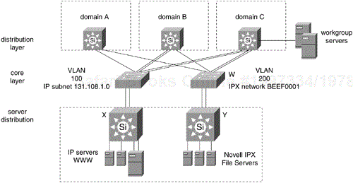
Another way to logically partition the core is by protocol. Create one VLAN for enterprise IP servers and another for enterprise IPX or DECnet servers. The logical partition can be extended to become complete physical separation on multiple core switches if dictated by security policies. Figure 12-15 shows the core separated physically into two switches. VLAN 100 on Switch V corresponds to IP subnet 131.108.1.0 where the World Wide Web (WWW) server farm attaches. VLAN 200 on Switch W corresponds to IPX network BEEF0001 where the Novell server farm attaches.
Of course, the simpler the backbone topology, the better. A small number of VLANs or ELANs is preferred. A discussion of the scaling issues related to large numbers of Layer 3 switches peered across many networks appears later in the section titled "Scaling Considerations."
It is very common for an enterprise to centralize servers. In some cases, services are consolidated into a single server. In other cases, servers are grouped at a data center for physical security or easier administration. At the same time, it is increasingly common for workgroups or individuals to publish a Web page locally and make it accessible to the enterprise.
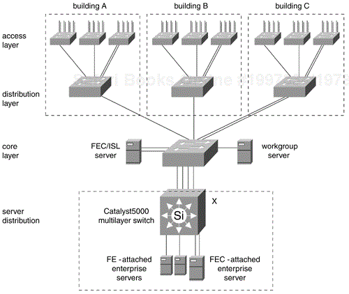
With centralized servers directly attached to the backbone, all client/server traffic crosses one hop from a subnet in the access layer to a subnet in the core. Policy-based control of access to enterprise servers is implemented by access lists applied at the distribution layer. In Figure 12-16, Server W is Fast Ethernet attached to the core subnet. Server X is Fast EtherChannel attached to the core subnet. As mentioned, servers attached directly to the core must use proxy ARP, IRDP, GDP, or RIP snooping to populate their routing tables. HSRP would not be used within core subnets, because switches in the distribution layer all connect to different parts of the campus.
Enterprise servers Y and Z are placed in a server farm by implementing multilayer switching in a server distribution building block. Server Y is Fast Ethernet attached, and server Z is Fast EtherChannel attached. Policy controlling access to these servers is implemented with access lists on the core switches. Another big advantage of the server distribution model is that HSRP can be used to provide redundancy with fast failover. The server distribution model also keeps all server-to-server traffic off the backbone.
Server M is within workgroup D, which corresponds to one VLAN. Server M is Fast Ethernet attached at a port on an access layer switch, because most of the traffic to the server is local to the workgroup. This follows the conventional 80/20 rule. Server M could be hidden from the enterprise with an access list at the distribution layer switch H if required.
Server N attaches to a distribution layer at switch H. Server N is a building-level server that communicates with clients in VLANs A, B, C, and D. A direct Layer 2 switched path between server N and clients in VLANs A, B, C, and D can be achieved in two ways. With four network interface cards (NICs), it can be directly attached to each VLAN. With an ISL NIC, server N can talk directly to all four VLANs over a VLAN trunk. Server N can be selectively hidden from the rest of the enterprise with an access list on distribution layer switch H if required.
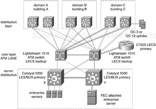
Figure 12-17 shows the multilayer campus model with ATM LANE in the backbone. For customers that require guaranteed quality of service (QoS), ATM is a good alternative. Real-time voice and video applications may mandate ATM features such as per-flow queuing, which provides granular control of delay and jitter.
Each Catalyst 5000 multilayer switch in the distribution layer is equipped with a LANE card. The LANE card acts as LEC so that the distribution layer switches can communicate across the backbone. The LANE card has a redundant ATM OC-3 or OC-12 physical interface called dual-PHY. In Figure 12-17, the solid lines represent the active link, and the dotted lines represent the hot-standby link. Two LightStream 1010 switches form the ATM core. Routers and servers with native ATM interfaces attach directly to ATM ports in the backbone. Enterprise servers in the server farm attach to multilayer Catalyst 5000 switches X and Y. Servers may be Fast Ethernet or Fast EtherChannel attached. These Catalyst 5000 switches are also equipped with LANE cards and act as LECS that connect Ethernet-based enterprise servers to the ATM ELAN in the core.
The trunks between the two LightStream 1010 core switches can be OC-3, OC-12, or OC-48, as required. The LightStream 1010 can be replaced by the Catalyst 8500 Multiservice router if higher capacity is needed. The PNNI protocol handles load balancing and intelligent routing between the ATM switches. Intelligent routing is increasingly important as the core scales up from two switches to many switches. STP is not used in the backbone. Intelligent Layer 3 routing protocols such as OSPF and Enhanced IGRP manage path determination and load balancing between distribution layer switches.
Cisco has implemented the Simple Server Redundancy Protocol (SSRP) to provide redundancy of the LECS and the LES/BUS. SSRP is available on Cisco 7500 routers, the Catalyst 5000 family of switches, and LightStream 1010 ATM switches. SSRP is compatible with all LANE 1.0 standard LECS.
The LANE card for the Catalyst 5000 family is an efficient BUS with broadcast performance of 120 kbps. This is enough capacity for the largest campus networks. Figure 12-17 shows the primary LES/BUS on Switch X and the backup LES/BUS on Switch Y. For a small campus SSRP, LES/BUS failover takes only a few seconds. For a very large campus, LES/BUS failover can take several minutes. In large campus designs, dual ELAN backbones are frequently used to provide fast convergence in the event of a LES/BUS failure.
As an example, two ELANs, Red and Blue, are created in the backbone. If the LES/BUS for ELAN Red is disconnected, traffic is quickly rerouted over ELAN Blue until ELAN Red recovers. After ELAN Red recovers, the multilayer switches in the distribution layer reestablish contact across ELAN Red and start load balancing between Red and Blue again. This process applies to routed protocols, but not to bridged protocols.
The primary and backup LECS database is configured on the LightStream 1010 ATM switches because of their central position. When the ELAN is operating in steady state, there is no overhead CPU utilization on the LECS. The LECS is contacted only when a new LEC joins an ELAN. For this reason, there are few performance considerations associated with placing the primary and backup LECS. A good choice for a primary LECS would be a Cisco 7500 router with direct ATM attachment to the backbone, because it would not be affected by ATM signaling traffic in the event of a LES/BUS failover.
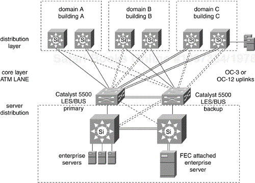
Figure 12-18 shows an alternative implementation of the LANE core using the Catalyst 5500 switch. Here the Catalyst 5500 operates as an ATM switch with the addition of the ATM Switch Processor (ASP) card. It is configured as a LEC with the addition of the OC-12 LANE/MPOA card. It is configured as an Ethernet frame switch with the addition of the appropriate Ethernet or Fast Ethernet line cards. The server farm is implemented with the addition of multilayer switching. The Catalyst 5500 combines the functionality of the LightStream 1010 and the Catalyst 5000 in a single chassis. It is also possible, thanks to the ATM fabric integration module (ATM FIM), to combine the functionality of the Catalyst 8510 SRP and the Catalyst 5500 in one chassis.
Applications based on IP multicast represent a small but rapidly growing component of corporate intranets. Applications such as IPTV, Microsoft NetShow, and NetMeeting are being tried and deployed. There are several aspects to handling multicasts effectively:
Multicast routing, protocol-independent multicast (PIM) dense mode, sparse mode, or sparse-dense mode
Clients and servers join multicast groups with Internet Group Management Protocol (IGMP)
Pruning multicast trees with Cisco Group Multicast Protocol (CGMP) or IGMP snooping
Switch and router multicast performance
Multicast policy
The preferred routing protocol for multicast is PIM. PIM sparse mode is described in RFC 2117, and PIM dense mode is on the standards track. PIM is being widely deployed in the Internet as well as in corporate intranets. As its name suggests, PIM works with various unicast routing protocols, such as OSPF and Enhanced IGRP. PIM routers may also be required to interact with the Distance Vector Multicast Routing Protocol (DVMRP). DVMRP is a legacy multicast routing protocol deployed in the Internet multicast backbone (MBONE). Currently 50% of the MBONE has converted to PIM, and it is expected that PIM will replace DVMRP over time.
PIM can operate in dense mode, sparse mode, or sparse-dense. Dense-mode operation is used for an application such as IPTV where there is a multicast server with many clients throughout the campus. Sparse-mode operation is used for workgroup applications such as NetMeeting. In either case, PIM builds efficient multicast trees that minimize the amount of traffic on the network. This is particularly important for high-bandwidth applications such as real-time video. In most environments, PIM is configured as sparse-dense and automatically uses either sparse mode or dense mode as required: The interface is treated as dense mode if the group is in dense mode; the interface is treated as sparse mode if the group is in sparse mode.
IGMP is used by multicast clients and servers to join or advertise multicast groups. The local gateway router makes a multicast available on subnets with active listeners, but blocks the traffic if no listeners are present. CGMP extends multicast pruning down to the Catalyst switch. A Cisco router sends out a CGMP message to advertise all the host MAC addresses that belong to a multicast group. Catalyst switches receive the CGMP message and forward multicast traffic only to ports with the specific MAC address in the forwarding table. This blocks multicast packets from all switch ports that don't have group members downstream. For Layer 3–capable switches, IGMP snooping is a more efficient alternative to CGMP, giving the switch enough intelligence to parse the IGMP packets originated from the clients and create the appropriate forwarding table entries.
Catalyst switches have an architecture that forwards multicast streams to one port, many ports, or all ports with no performance penalty. Catalyst switches will support one or many multicast groups operating at wire-speed concurrently.
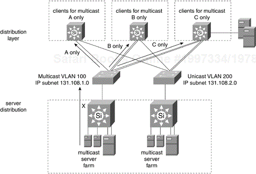
One way to implement multicast policy is to place multicast servers in a server farm behind multilayer Catalyst Switch X, as shown in Figure 12-19. Switch X acts as a multicast firewall that enforces rate limiting and controls access to multicast sessions. To further isolate multicast traffic, create a separate multicast VLAN/subnet in the core. The multicast VLAN in the core could be a logical partition of existing core switches or a dedicated switch if traffic is very high. Switch X is a logical place to implement the PIM rendezvous point. The rendezvous point is like the root of the multicast tree.
The multilayer design model is inherently scalable. Layer 3 switching performance scales because it is distributed. Backbone performance scales as you add more links or more switches. The individual switch domains or buildings scale to more than 1,000 client devices with two distribution layer switches in a typical redundant configuration. More building blocks or server blocks can be added to the campus without changing the design model. Because the multilayer design model is highly structured and deterministic, it is also scalable from a management and administration perspective.
In all the multilayer designs discussed, STP loops in the backbone have been avoided. STP takes 40 to 50 seconds to converge and does not support load balancing across multiple paths. Within Ethernet backbones, no loops are configured. For ATM backbones, PNNI handles load balancing. In all cases, intelligent Layer 3 routing protocols such as OSPF and Enhanced IGRP handle path determination and load balancing over multiple paths in the backbone.
OSPF overhead in the backbone rises linearly as the number of distribution layer switches rises. This is because OSPF elects one designated router and one backup designated router to peer with all the other Layer 3 switches in the distribution layer. If two VLANs or ELANs are created in the backbone, a designated router and a backup are elected for each. Therefore, the OSPF routing traffic and CPU overhead increase as the number of backbone VLANs or ELANs increases. For this reason, it is recommended to keep the number of VLANs or ELANs in the backbone small. For large ATM/LANE backbones, it is recommended to create two ELANs in the backbone, as discussed earlier in the section titled "ATM/LANE Backbone."
Another important consideration for OSPF scalability is summarization. For a large campus, make each building an OSPF area and make the distribution layer switches Area Border Routers (ABRs). Pick all the subnets within the building from a contiguous block of addresses and summarize with a single summary advertisement at the ABRs. This reduces the amount of routing information throughout the campus and increases the stability of the routing table. Enhanced IGRP can be configured for summarization in the same way.
Not all routing protocols are created equal, however. AppleTalk Routing Table Maintenance Protocol (RTMP), Novell Server Advertisement Protocol (SAP), and Novell Routing Information Protocol (RIP) are protocols with overhead that increases as the square of the number of peers. Assume, for example, that 12 distribution layer switches are attached to the backbone and are running Novell SAP. If 100 SAP services are being advertised throughout the campus, each distribution switch injects 100/7 = 15 SAP packets into the backbone every 60 seconds. All 12 distribution layer switches receive and process 12 × 15 = 180 SAP packets every 60 seconds. The Cisco IOS software provides features such as SAP filtering to contain SAP advertisements from local servers where appropriate. The 180 packets are a reasonable number, but consider what happens with 100 distribution layer switches advertising 1,000 SAP services.
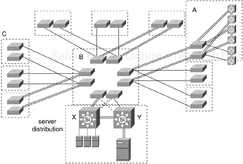
Figure 12-20 shows a design for a large hierarchical, redundant ATM campus backbone. The ATM core designated B consists of eight LightStream 1010 switches with a partial mesh of OC-12 trunks. Domain C consists of three pairs of LightStream 1010 switches. Domain C can be configured with an ATM prefix address that is summarized where it connects to the core B. On this scale, manual ATM address summarization would have little benefit. The default summarization would have just 26 routing entries corresponding to the 26 switches in Figure 12-20. In domain A, pairs of distribution layer switches attach to the ATM fabric with OC-3 LANE. A server farm behind Catalyst switches X and Y attaches directly to the core with OC-12 LANE/MPOA cards.
The multilayer design model describes the logical structure of the campus. The addressing and Layer 3 design are independent of choice of media. The logical design principles are the same whether implemented with Ethernet, Token Ring, FDDI, or ATM. This is not always true in the case of bridged protocols such as NetBIOS and Systems Network Architecture (SNA), which are media-dependent. In particular, Token Ring applications with frame sizes larger than the 1500 bytes allowed by Ethernet need to be considered.
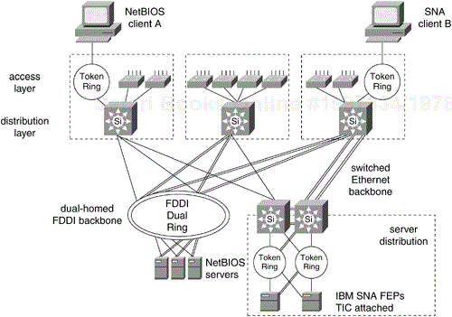
Figure 12-21 shows a multilayer campus with a parallel FDDI backbone. The FDDI backbone could be bridged to the Switched Fast Ethernet backbone with translational bridging implemented at the distribution layer. Alternatively, the FDDI backbone could be configured as a separate logical network. There are several possible reasons for keeping an existing FDDI backbone in place. FDDI supports 4500-byte frames, while Ethernet frames can be no larger than 1500 bytes. This is important for bridged protocols that originate on Token Ring end systems that generate 4500-byte frames. Another reason to maintain an FDDI backbone is for enterprise servers that have FDDI network interface cards.
Data-link switching plus (DLSw+) is Cisco's implementation of standard DLSw. SNA frames from native SNA client B are encapsulated in TCP/IP by a router or a distribution layer switch in the multilayer model. A distribution switch deencapsulates the SNA traffic out to a Token Ring–attached front-end processor (FEP) at a data center. Multilayer switches can be attached to Token Ring with the Versatile Interface Processor (VIP) card and the Token Ring port adapter (PA).
Access control lists are supported by multilayer switching with no performance degradation. Because all traffic passes through the distribution layer, this is the best place to implement policy with access control lists. These lists can also be used in the control plane of the network to restrict access to the switches themselves. In addition, the TACACS+ and RADIUS protocols provide centralized access control to switches. The Cisco IOS software also provides multiple levels of authorization with password encryption. Network managers can be assigned to a particular level at which a specific set of commands are enabled.
Implementing Layer 2 switching at the access layer and in the server farm has immediate security benefits. With shared media, all packets are visible to all users on the logical network. It is possible for a user to capture clear-text passwords or files. On a switched network, conversations are visible only to the sender and receiver. And within a server farm, all server-to-server traffic is kept off the campus backbone.
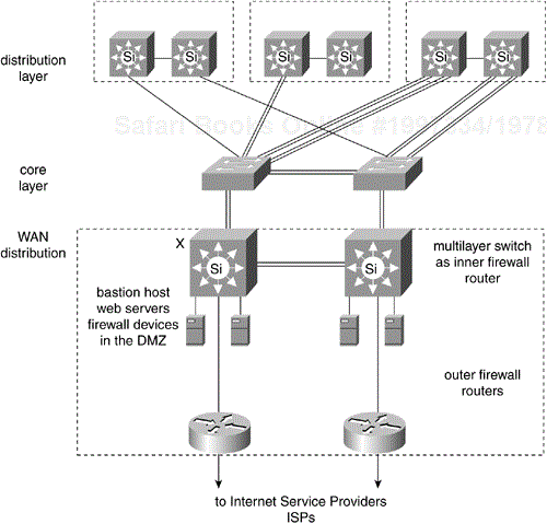
WAN security is implemented in firewalls. A firewall consists of one or more routers and bastion host systems on a special network called a demilitarized zone (DMZ). Specialized Web-caching servers and other firewall devices may attach to the DMZ. The inner firewall routers connect to the campus backbone in what can be considered a WAN distribution layer.
Figure 12-22 shows a WAN distribution building block with firewall components.
For nonrouted protocols, bridging is configured. Bridging between access layer VLANs and the backbone is handled by the RSM, the Catalyst 6000 MSM/MSFC, or the 8500 switching router. Because each access layer VLAN is running IEEE spanning tree, the RSM must not be configured with an IEEE bridge group. The effect of running IEEE bridging on the RSM is to collapse all the spanning trees of all the VLANs into a single spanning tree with a single root bridge. Configure the RSM with a DEC STP bridge group to keep all the IEEE spanning trees separate. Remember that LAN switches run the IEEE STP only. It is recommended to run a recent version of IOS on the RSM (or MSM, or SRP) to allow the DEC bridge protocol data units (BPDUs) to pass between RSMs through the Catalyst Layer 2 switches in a transparent fashion.
This chapter has discussed several variations of the multilayer campus design model. Whether implemented with frame-switched Ethernet backbones or cell-switched ATM backbones, all share the same basic advantages. The model is highly deterministic, which makes it easy to troubleshoot as it scales. The modular building-block approach scales easily as new buildings or server farms are added to the campus. Intelligent Layer 3 routing protocols such as OSPF and Enhanced IGRP handle load balancing and fast convergence across the backbone. The logical structure and addressing of the hub-and-router model are preserved, which makes migration much easier. Many value-added services of the Cisco IOS software, such as server proxy, tunneling, and summarization are implemented in the Catalyst multilayer switches at the distribution layer. Policy is also implemented with access lists at the distribution layer or at the server distribution switches.
Redundancy and fast convergence are provided by features such as UplinkFast and HSRP. Bandwidth scales from Fast Ethernet to Fast EtherChannel to Gigabit Ethernet without changing addressing or policy configuration. With the features of the Cisco IOS software, the multilayer model supports all common campus protocols, including TCP/IP, AppleTalk, Novell IPX, DECnet, IBM SNA, NetBIOS, and many more. Many of the largest and most successful campus intranets are built with the multilayer model. It avoids all the scaling problems associated with flat bridged or switched designs. And finally, the multilayer model with multilayer switching handles Layer 3 switching in hardware with no performance penalty compared with Layer 2 switching.
Campus LAN designs use switches to replace traditional hubs and use an appropriate mix of routers to minimize broadcast radiation. With the appropriate pieces of software and hardware in place, and adhering to good network design, it is possible to build topologies, such as the examples described in the Switched LAN Network Designs section earlier in this chapter.

