Edited by Christopher Beveridge
This chapter focuses on the implementation of packet-switching services, and addresses network design in terms of the following packet-switching service topics:
Hierarchical network design
Topology design
Broadcast issues
Performance issues
Information provided in this chapter is organized around these central topics. An introductory discussion outlines the general issues; subsequent discussions focus on considerations for the specific packet-switching technologies.
This chapter focuses on general packet-switching considerations and Frame Relay networks. Frame Relay was selected as the focus for this chapter because it presents a comprehensive illustration of design considerations for interconnection to packet-switching services. Also included in this chapter is an introductory discussion of design and performance issues when integrating data and voice on a Frame Relay network.
The chief trade-off in linking local-area networks (LANs) and private wide-area networks (WANs) into packet-switching data network (PSDN) services is between cost and performance. An ideal design optimizes packet services. Service optimization does not necessarily translate into picking the service mix that represents the lowest possible tariffs. Successful packet-service implementations result from adhering to two basic rules:
When implementing a packet-switching solution, be sure to balance the cost savings derived by instituting PSDN interconnections against your computing community's performance requirements.
Build an environment that is manageable and that can scale up as more WAN links are required.
These rules recur as underlying themes in the discussions that follow. The introductory sections outline the overall issues that influence the ways in which packet-switched networks are designed.
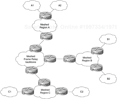
The objective of a hierarchical network design is to modularize the elements of a large network into layers of networking. The general model of this hierarchy is described in Chapter 2, "Network Design Basics." The key functional layers in this model are the access, distribution, and backbone (or core) routing layers. In essence, a hierarchical approach strives to split networks into subnetworks so that traffic and nodes can be more easily managed. Hierarchical designs also facilitate scaling of networks because new subnetwork modules and networking technologies can be integrated into the overall scheme without disrupting the existing backbone. Figure 6-1 illustrates the basic approach to hierarchical design.
Three basic advantages tilt the design decision in favor of a hierarchical approach:
Scalability of Hierarchical Networks
Manageability of Hierarchical Networks
Optimization of Broadcast and Multicast Control Traffic
Scalability is a primary advantage that supports using a hierarchical approach to packet-service connections. Hierarchical networks are more scalable because they enable you to grow your network in incremental modules without running into the limitations that are quickly encountered with a flat, nonhierarchical structure.
Hierarchical networks raise certain issues that require careful planning, however. These issues include the costs of virtual circuits, the complexity inherent in a hierarchical design (particularly when integrated with a meshed topology), and the need for additional router interfaces to separate layers in your hierarchy.
To take advantage of a hierarchical design, you must match your hierarchy of networks with a complementary approach in your regional topologies. Design specifics depend on the packet services you implement, as well as on your requirements for fault tolerance, cost, and overall performance.
Hierarchical designs offer several management advantages:
Network simplicity—. Adopting a hierarchical design reduces the overall complexity of a network by partitioning elements into smaller units. This partitioning of elements makes troubleshooting easier, while providing inherent protection against the propagation of broadcast storms, routing loops, or other potential problems.
Design flexibility—. Hierarchical network designs provide greater flexibility in the use of WAN packet services. Most networks benefit from using a hybrid approach to the overall network structure. In many cases, leased lines can be implemented in the backbone, with packet-switching services used in the distribution and access networks.
Router management—. With the use of a layered, hierarchical approach to router implementation, the complexity of individual router configurations is substantially reduced because each router has fewer neighbors or peers with which to communicate.
The effect of broadcasting in packet-service networks (discussed in "Broadcast Issues," later in this chapter) requires you to implement smaller groups of routers. Typical examples of broadcast traffic are the routing updates and Novell Service Advertisement Protocol (SAP) updates broadcast between routers on a PSDN. An excessively high population of routers in any area or layer of the overall network might result in traffic bottlenecks brought on by broadcast replication. A hierarchical scheme enables you to limit the level of broadcasting between regions and into your backbone.
After you have established your overall network scheme, you must settle on an approach for handling interconnections among sites within the same administrative region or area. In designing any regional WAN, whether it is based on packet-switching services or point-to-point interconnections, you can adopt three basic design approaches:
Star Topologies
Fully Meshed Topologies
Partially Meshed Topologies
The following discussions introduce these topologies. Technology-specific discussions presented in this chapter address the applicability of these topologies for the specific packet-switching services.
Illustrations in this chapter use lines to show the interconnections of specific routers on the PSDN network. These interconnections are virtual connections, facilitated by mapping features within the routers. Actual physical connections generally are made to switches within the PSDN. Unless otherwise specified, the connecting lines represent these virtual connections in the PSDN.
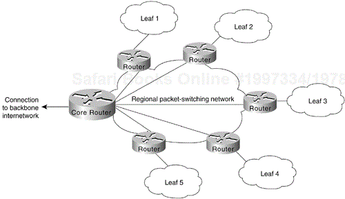
A star topology features a single networking hub, providing access from leaf networks into the backbone and access to each other only through the core router. Figure 6-2 illustrates a packet-switched star topology for a regional network.
The advantages of a star approach are simplified management and minimized tariff costs. However, the disadvantages are significant. First, the core router represents a single point of failure. Second, the core router limits overall performance for access to backbone resources because it is a single pipe through which all traffic intended for the backbone (or for the other regional routers) must pass. Third, this topology is not scalable.
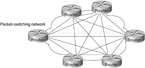
A fully meshed topology means that each routing node on the periphery of a given packet-switching network has a direct path to every other node on the cloud. Figure 6-3 illustrates this kind of arrangement.
The key rationale for creating a fully meshed environment is to provide a high level of redundancy. Although a fully meshed topology facilitates support of all network protocols, it is not tenable in large packet-switched networks. Key issues are the large number of virtual circuits required (one for every connection between routers), problems associated with the large number of packet/broadcast replications required, and the configuration complexity for routers in the absence of multicast support in nonbroadcast environments.
By combining fully meshed and star approaches into a partially meshed environment, you can improve fault tolerance without encountering the performance and management problems associated with a fully meshed approach. The next section discusses the partially meshed approach.
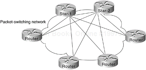
A partially meshed topology reduces the number of routers within a region that have direct connections to all other nodes in the region. All nodes are not connected to all other nodes. For a nonmeshed node to communicate with another nonmeshed node, it must send traffic through one of the collection point routers. Figure 6-4 illustrates such a situation.
There are many forms of partially meshed topologies. In general, partially meshed approaches are considered to provide the best balance for regional topologies in terms of the number of virtual circuits, redundancy, and performance.
The existence of broadcast traffic can present problems when introduced into packet-service networks. Broadcasts are necessary for a station to reach multiple stations with a single packet when the sending node does not know the specific address of each intended recipient. Table 6-1 lists common networking protocols and the general level of broadcast traffic associated with each, assuming a large-scale network with many routing nodes.
Table 6-1. Broadcast Traffic Levels of Protocols in Large-Scale Networks
The relative values high and low in Table 6-1 provide a general range for these protocols. Your situation and implementation will determine the magnitude of broadcast traffic. For example, the level of broadcast traffic generated in an AppleTalk Enhanced IGRP environment depends on the setting of the Enhanced IGRP hello-timer interval. Another issue relates to the size of the network. In a small-scale network, the amount of broadcast traffic generated by Enhanced IGRP nodes might be higher than with a comparable RTMP-based network. For large-scale networks, however, Enhanced IGRP nodes generate substantially less broadcast traffic than RTMP-based nodes.
Managing packet replication is an important design consideration when integrating broadcast-type LANs (such as Ethernet) with nonbroadcast packet services (such as X.25). With the multiple virtual circuits, characteristic of connections to packet-switched environments, routers must replicate broadcasts for each virtual circuit on a given physical line.
With highly meshed environments, replicating broadcasts can be expensive in terms of increased required bandwidth and the number of CPU cycles. Despite the advantages that meshed topologies offer, they are generally impractical for large packet-switching networks. Nonetheless, some level of circuit meshing is essential to ensure fault tolerance. The key is to balance the trade-off in performance against requirements for circuit redundancy.
When designing a WAN around a specific packet-service type, you must consider the individual characteristics of the virtual circuit. Performance under certain conditions will depend on a given virtual circuit's capability to accommodate mixed protocol traffic, for example. Depending on how the multiprotocol traffic is queued and streamed from one node to the next, certain protocols may require special handling. One solution might be to assign specific virtual circuits to specific protocol types. Performance concerns for specific packet-switching services include committed information rates (CIR) in Frame Relay networks and window size limitations in X.25 networks. (The CIR corresponds to the maximum average rate per connection [PVC] for a period of time.)
One of the chief concerns when designing a Frame Relay implementation is scalability. As your requirements for remote interconnections grow, your network must be able to grow to accommodate changes. The network must also provide an acceptable level of performance, while minimizing maintenance and management requirements. Meeting all these objectives simultaneously can be quite a balancing act. The discussions that follow focus on several important factors for Frame Relay networks:
Hierarchical design
Regional topologies
Broadcast issues
Performance issues
The guidelines and suggestions that follow are intended to provide a foundation for constructing scalable Frame Relay networks that balance performance, fault tolerance, and cost.
In general, the arguments supporting hierarchical design for packet-switching networks, discussed in the section titled Hierarchical Design earlier in this chapter, apply to hierarchical design for Frame Relay networks. To review, the three factors driving the recommendation for implementing a hierarchical design are the following:
Scalability of hierarchical networks
Manageability of hierarchical networks
Optimization of broadcast and multicast control traffic
The method by which many Frame Relay vendors tariff services is by Data Link Connection Identifier (DLCI), which identifies a Frame Relay permanent virtual connection. A Frame Relay permanent virtual connection is equivalent to an X.25 permanent virtual circuit, which, in X.25 terminology, is identified by a logical channel number (LCN). The DLCI defines the interconnection between Frame Relay elements. For any given network implementation, the number of Frame Relay permanent virtual connections is highly dependent on the protocols in use and actual traffic patterns.
How many DLCIs can be configured per serial port? It varies, depending on the traffic level. You can use all of them (about 1,000), but in common use, 200–300 is a typical maximum. If you broadcast on the DLCIs, 30–50 is more realistic due to CPU overhead in generating broadcasts. Specific guidelines are difficult because overhead varies by configuration. On low-end boxes (4,500 and below), however, the architecture is bound by the available I/O memory. The specific number depends on several factors that should be considered together:
Protocols being routed—. Any broadcast-intensive protocol constrains the number of assignable DLCIs. For example, AppleTalk is a protocol characterized by high levels of broadcast overhead. Another example is Novell IPX, which sends both routing and service updates resulting in higher broadcast bandwidth overhead. In contrast, IGRP is less broadcast-intensive because it sends routing updates less often (by default, every 90 seconds). However, IGRP can become broadcast-intensive if its IGRP timers are modified so that updates are sent more frequently.
Broadcast traffic—. Broadcasts, such as routing updates, are the single most important consideration in determining the number of DLCIs that can be defined. The amount and type of broadcast traffic will guide your ability to assign DLCIs within this general recommended range. Refer to Table 6-1, earlier in this chapter, for a list of the relative level of broadcast traffic associated with common protocols.
Speed of lines—. If broadcast traffic levels are expected to be high, you should consider faster lines and DLCIs with higher CIR and excess burst (Be) limits. You should also implement fewer DLCIs.
Static routes—. If static routing is implemented, you can use a larger number of DLCIs per line because a larger number of DLCIs reduces the level of broadcasting.
Size of routing protocol and SAP updates—. The larger the network, the larger the size of these updates. The larger the updates, the fewer the number of DLCIs that you can assign.
Two forms of hierarchical design can be implemented:
Hierarchical Meshed Frame Relay Networks
Hybrid-Meshed Frame Relay Networks
Both designs have advantages and disadvantages. The brief discussions that follow contrast these two approaches.
The objectives of implementing a hierarchical mesh for Frame Relay environments are to avoid implementing excessively large numbers of DLCIs and to provide a manageable, segmented environment. The hierarchical meshed environment features full meshing within the core PSDN and full meshing throughout the peripheral networks. The hierarchy is created by strategically locating routers between network elements in the hierarchy.
Figure 6-5 illustrates a simple hierarchical mesh. The network illustrated in Figure 6-5 illustrates a fully meshed backbone, with meshed regional networks and broadcast networks at the outer periphery.
The key advantages of the hierarchical mesh are that it scales well and localizes traffic. By placing routers between fully meshed portions of the network, you limit the number of DLCIs per physical interface, segment your network, and make the network more manageable. However, consider the following two issues when implementing a hierarchical mesh:
Broadcast and packet replication—. In an environment that has a large number of multiple DLCIs per router interface, excessive broadcast and packet replication can impair overall performance. With a high level of meshing throughout a hierarchical mesh, excessive broadcast and packet replication is a significant concern. In the backbone, where traffic throughput requirements are typically high, preventing bandwidth loss due to broadcast traffic and packet replication is particularly important.
Increased costs associated with additional router interfaces—. Compared with a fully meshed topology, additional routers are needed to separate the meshed backbone from the meshed peripheral networks. By using these routers, however, you can create much larger networks that scale almost indefinitely in comparison to a fully meshed network.
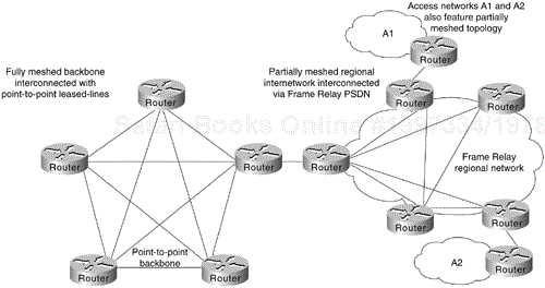
The economic and strategic importance of backbone environments often force network designers to implement a hybrid-meshed approach to WAN networks. Hybrid-meshed networks feature redundant, meshed leased lines in the WAN backbone and partially (or fully) meshed Frame Relay PSDNs in the periphery. Routers separate the two elements. Figure 6-6 illustrates such a hybrid arrangement.
Hybrid hierarchical meshes have the advantages of providing higher performance on the backbone, localizing traffic, and simplifying scaling of the network. In addition, hybrid-meshed networks for Frame Relay are attractive because they can provide better traffic control in the backbone and they allow the backbone to be made of dedicated links, resulting in greater stability.
The disadvantages of hybrid hierarchical meshes include the high costs associated with the leased lines, as well as broadcast and packet replication that can be significant in access networks.
You can adopt one of three basic design approaches for a Frame Relay–based packet service regional network:
Star Topologies
Fully Meshed Topologies
Partially Meshed Topologies
Each of these is discussed in the following sections. In general, emphasis is placed on partially meshed topologies integrated into a hierarchical environment. Star and fully meshed topologies are discussed for structural context.
The general form of the star topology is addressed in the section titled "Topology Design," earlier in this chapter. Stars are attractive because they minimize the number of DLCIs required and result in a low-cost solution. A star topology presents some inherent bandwidth limitations, however. Consider an environment in which a backbone router is attached to a Frame Relay cloud at 256 kbps, whereas the remote sites are attached at 56 kbps. Such a topology will throttle traffic coming off the backbone intended for the remote sites.
As suggested in the general discussion, a strict star topology does not offer the fault tolerance needed for many networking situations. If the link from the hub router to a specific leaf router is lost, all connectivity to the leaf router is lost.
A fully meshed topology mandates that every routing node connected to a Frame Relay network be logically linked via an assigned DLCI to every other node on the cloud. This topology is not tenable for larger Frame Relay networks for several reasons:
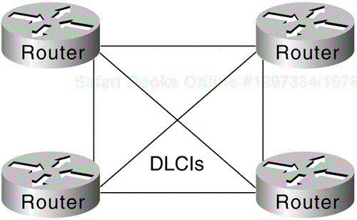
Large, fully meshed Frame Relay networks require many DLCIs. One is required for each logical link between nodes. As shown in Figure 6-7, a fully connected topology requires the assignment of [n(n – 1)]/2 DLCIs, where n is the number of routers to be directly connected.
Broadcast replication will choke networks in large, meshed Frame Relay topologies. Routers inherently treat Frame Relay as a broadcast medium. Each time a router sends a multicast frame (such as a routing update, spanning-tree update, or SAP update), the router must copy the frame to each DLCI for that Frame Relay interface.
These problems combine to make fully meshed topologies unworkable and unscalable for all but relatively small Frame Relay implementations.
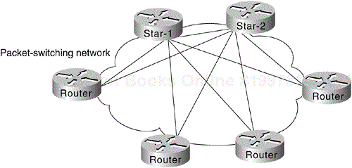
Combining the concepts of the star topology and the fully meshed topology results in the partially meshed topology. Partially meshed topologies are generally recommended for Frame Relay regional environments because they offer superior fault tolerance (through redundant stars) and are less expensive than a fully meshed environment. In general, you should implement the minimum meshing to eliminate single point-of-failure risk.
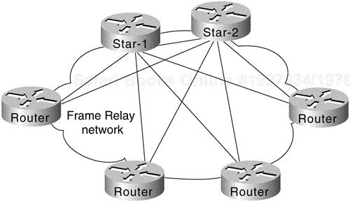
Figure 6-8 illustrates a twin-star, partially meshed approach. This arrangement is supported in Frame Relay networks running IP, ISO CLNS, DECnet, Novell IPX, AppleTalk, and bridging.
A feature called virtual interfaces (introduced with Software Release 9.21) enables you to create networks using partially meshed Frame Relay designs, as shown in Figure 6-8.
To create this type of network, individual physical interfaces are split into multiple virtual (logical) interfaces. The implication for Frame Relay is that DLCIs can be grouped or separated to maximize utility. Small fully meshed clouds of Frame Relay–connected routers can travel over a group of four DLCIs clustered on a single virtual interface, for example, whereas a fifth DLCI on a separate virtual interface provides connectivity to a completely separate network. All this connectivity occurs over a single physical interface connected to the Frame Relay service.
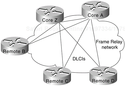
Prior to Software Release 9.21, virtual interfaces were not available and partially meshed topologies posed potential problems, depending on the network protocols used. Consider the topology illustrated in Figure 6-9.
Given a standard router configuration and router software predating Software Release 9.21, the connectivity available in the network shown in Figure 6-9 can be characterized as follows:
Core A and Core Z can reach all the remote routers.
Remote B, Remote C, and Remote D cannot reach each other.
For Frame Relay implementations running software prior to Software Release 9.21, the only way to permit connectivity among all these routers is by using a distance vector routing protocol that can disable split horizon, such as RIP or IGRP for IP. Any other network protocol, such as AppleTalk or ISO CLNS, does not work. The following configuration listing illustrates an IGRP configuration to support a partially meshed arrangement:
  router igrp 20
  network 45.0.0.0
  !
  interface serial 3
  encapsulation frame-relay
  ip address 45.1.2.3 255.255.255.0
  no ip split-horizon
This topology works with distance vector routing protocols, assuming that you want to establish connectivity from Remote B, C, or D to Core A or Core Z only, but not across paths. This topology does not work with link-state routing protocols because the router cannot verify complete adjacencies. Note that you will see routes and services of the leaf nodes that cannot be reached.
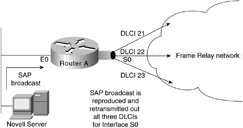
Routers treat Frame Relay as a broadcast medium, which means that each time the router sends a multicast frame (such as a routing update, spanning-tree update, or SAP update), the router must replicate the frame to each DLCI for the Frame Relay interface. Frame replication results in substantial overhead for the router and for the physical interface.
Consider a Novell IPX environment with multiple DLCIs configured for a single physical serial interface. Every time a SAP update is detected, which occurs every 60 seconds, the router must replicate it and send it down the virtual interface associated with each DLCI. Each SAP frame contains up to seven service entries, and each update is 64 bytes. Figure 6-10 illustrates this situation.
One way to reduce broadcasts is to implement more efficient routing protocols, such as Enhanced IGRP, and to adjust timers on lower-speed Frame Relay services.
Very large Frame Relay networks might have performance problems when many DLCIs terminate in a single router or access server that must replicate routing updates and service advertising updates on each DLCI. The updates can consume access-link bandwidth and cause significant latency variations in user traffic; the updates can also consume interface buffers and lead to higher packet-rate loss for both user data and routing updates.
To avoid such problems, you can create a special broadcast queue for an interface. The broadcast queue is managed independently of the normal interface queue, has its own buffers, and has a configurable size and service rate.
A broadcast queue is given a maximum transmission rate (throughput) limit, measured in both bytes per second and packets per second. The queue is serviced to ensure that no more than this maximum is provided. The broadcast queue has priority when transmitting at a rate below the configured maximum, and hence has a guaranteed minimum bandwidth allocation. The two transmission rate limits are intended to avoid flooding the interface with broadcasts. The actual transmission-rate limit in any second is the first of the two rate limits that is reached.
Two important performance concerns must be addressed when you are implementing a Frame Relay network:
Packet-Switched Service Provider Tariff Metrics
Multiprotocol Traffic Management Requirements
Each of these must be considered during the network planning process. The following sections briefly discuss the impact that tariff metrics and multiprotocol traffic management can have on overall Frame Relay performance.
When you contract with Frame Relay packet-switched service providers for specific capabilities, CIR (measured in bits per second) is one of the key negotiated tariff metrics. CIR is the maximum permitted traffic level that the carrier will allow on a specific DLCI into the packet-switching environment. CIR can be anything up to the capacity of the physical limitation of the connecting line.
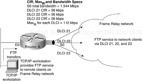
Other key metrics are committed burst (Bc) and excess burst (Be). Bc is the number of bits that the Frame Relay network is committed to accept and transmit at the CIR. Be sets the absolute limit for a DLCI in bits. This is the number of bits that the Frame Relay network will attempt to transmit after Bc is accommodated. Be determines a peak or maximum Frame Relay data rate (MaxR), where MaxR = (Bc + Be)/Bc × CIR, measured in bits per second.
Consider the situation illustrated in Figure 6-11. In this environment, DLCIs 21, 22, and 23 are assigned CIRs of 56 kbps. Assume that the MaxR for each line is 112 kbps (double the CIR). The serial line to which Router A is connected is a T1 line capable of 1.544 Mbps total throughput. Given that the type of traffic being sent into the Frame Relay network consists of FTP file transfers, the potential is high that the router will attempt to transmit at a rate in excess of MaxR. If this occurs, traffic might be dropped without notification if the Be buffers (allocated at the Frame Relay switch) overflow.
Unfortunately, there are relatively few ways to automatically prevent traffic on a line from exceeding the MaxR. Although Frame Relay itself uses the Forward Explicit Congestion Notification (FECN) and Backward Explicit Congestion Notification (BECN) protocols to control traffic in the Frame Relay network, there is no formally standardized mapping between the Frame Relay (link) level and most upper-layer protocols. At this time, an FECN bit detected by a router is mapped to the congestion notification byte for DECnet Phase IV or ISO CLNS. No other protocols are supported.
The actual effect of exceeding specified CIR and derived MaxR settings depends on the types of application running on the network. TCP/IP's backoff algorithm will see dropped packets as a congestion indication, for instance, and sending hosts might reduce output. NFS has no backoff algorithm, however, and dropped packets will result in lost connections. When determining the CIR, Bc, and Be for Frame Relay connection, you should consider the actual line speed and applications to be supported.
Most Frame Relay carriers provide an appropriate level of buffering to handle instances when traffic exceeds the CIR for a given DLCI. These buffers allow excess packets to be spooled at the CIR and reduce packet loss, given a robust transport protocol such as TCP. Nonetheless, overflows can happen. Remember that although routers can prioritize traffic, Frame Relay switches cannot. You can specify which Frame Relay packets have low priority or low time sensitivity and will be the first to be dropped when a Frame Relay switch is congested. The mechanism that allows a Frame Relay switch to identify such packets is the discard eligibility (DE) bit.
This feature requires that the Frame Relay network be able to interpret the DE bit. Some networks take no action when the DE bit is set. Other networks use the DE bit to determine which packets to discard. The most desirable interpretation is to use the DE bit to determine which packets should be dropped first and also which packets have lower time sensitivity. You can define DE lists that identify the characteristics of packets to be eligible for discarding, and you can also specify DE groups to identify the DLCI that is affected.
You can specify DE lists based on the protocol or the interface, and on characteristics such as fragmentation of the packet, a specific TCP or User Datagram Protocol (UDP) port, an access list number, or a packet size.
Note
To avoid packet loss, implement unacknowledged application protocols (such as packetized video) carefully. With these protocols, there is a greater potential for buffer overflow.
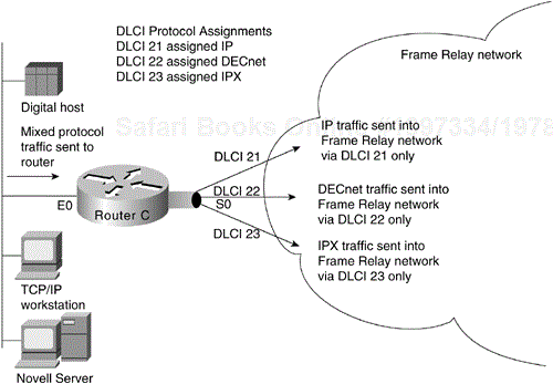
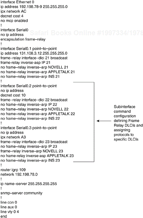
With multiple protocols being transmitted into a Frame Relay network through a single physical interface, you might find it useful to separate traffic among different DLCIs, based on protocol type. To split traffic in this way, you must assign specific protocols to specific DLCIs. This can be done by specifying static mapping on a per–virtual interface basis or by defining only specific types of encapsulations for specific virtual interfaces.
Figure 6-12 illustrates the use of virtual interfaces (assigned using subinterface configuration commands) to allocate traffic to specific DLCIs. In this case, traffic of each configured protocol is sent down a specific DLCI and segregated on a per-circuit basis. In addition, each protocol can be assigned a separate CIR and a separate level of buffering by the Frame Relay service provider.
Figure 6-13 provides a listing of the subinterface configuration commands needed to support the configuration illustrated in Figure 6-12. The command listing in Figure 6-13 illustrates the enabling of the relevant protocols and the assignment of the protocols to the specific subinterfaces and associated Frame Relay DLCIs. Software Release 9.1 and later uses Frame Relay Inverse Address Resolution Protocol (IARP) to map protocol addresses to Frame Relay DLCIs dynamically. For that reason, Figure 6-13 does not show Frame Relay mappings.
You can use the following commands in Software Release 9.1 and later to achieve a configuration similar to the configuration shown in Figure 6-13:
  Version 9.1
  interface serial 0
  ip address 131.108.3.12 255.255.255.0
  decnet cost 10
  novell network A3
  frame-relay map IP 131.108.3.62 21 broadcast
  frame-relay map DECNET 10.3 22 broadcast
  frame-relay map NOVELL C09845 23 broadcast
Beginning with Release 11.2, Cisco IOS supports Frame Relay traffic shaping, which provides the following features:
Rate enforcement on a per-virtual circuit basis—. The peak rate for outbound traffic can be set to the CIR or some other user-configurable rate.
Dynamic traffic throttling on a per-virtual circuit basis—. When BECN packets indicate congestion on the network, the outbound traffic rate is automatically stepped down; when congestion eases, the outbound traffic rate is stepped up again. This feature is enabled by default.
Enhanced queuing support on a per-virtual circuit basis—. Either custom queuing or priority queuing can be configured for individual virtual circuits.
By defining separate virtual circuits for different types of traffic, and specifying queuing and an outbound traffic rate for each virtual circuit, you can provide guaranteed bandwidth for each type of traffic. By specifying different traffic rates for different virtual circuits over the same time, you can perform virtual time division multiplexing. By throttling outbound traffic from high-speed lines in central offices to low-speed lines in remote locations, you can ease congestion and data loss in the network; enhanced queuing also prevents congestion-caused data loss. Traffic shaping applies to both PVCs and SVCs.
Unlike most data applications, which can tolerate delay, voice communications must be performed in near real time. This means that transmission and network delays must be kept low enough and constant enough to remain imperceptible to the user. Historically, packetized voice transmission was impossible, due to the voice bandwidth requirements and transmission delays associated with packet-based networks. Also, integrating voice over data networks has only recently been well understood because of the challenges of designing and building a network that can accommodate the two very different types of traffic: data and voice. The remainder of this chapter is an introduction to the design and implementation characteristics of voice traffic and its behavior on a Frame Relay network.
Human speech contains a significant amount of redundant information that is necessary for communications to occur in a conversation between persons in the same room, but which is not needed for a conversation to occur over a communications network. Typically, only 20% of a conversation consists of essential speech components that need to be transmitted for a successful voice conversation. The balance is made up of pauses, background noise, and repetitive patterns.
Packetized voice is possible and higher bandwidth efficiencies are attained by analyzing and processing only the essential components of the voice sample, instead of attempting to digitize the entire voice sample (with all the associated pauses and repetitive patterns). Current speech-processing technology takes the voice-digitizing process several steps further than conventional encoding methods.
Repetitive sounds are part of human speech, and are easily compressed. In a normal conversation, only about half of what is spoken will reach the listener's ear. In a typical communications network, however, all speech content is encoded and transmitted. Transmission of these identical sounds is not necessary and their removal can increase bandwidth efficiency.
A person speaking does not provide a continuous stream of information. Pauses between words and sentences, and those gaps that come at the end of one person talking but before the other begins, also can be removed to increase bandwidth efficiency. The pauses may be represented in compressed form, and then can be regenerated at the destination to maintain the natural quality of the spoken communication.
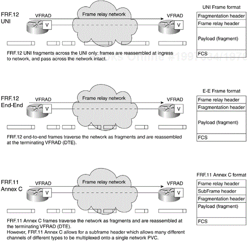
After the removal of repetitive patterns and silent periods, the remaining speech information may then be digitized and placed into voice packets suitable for transmission over Frame Relay networks. These packets or frames also tend to be smaller than average data frames. These frame sizes and the compression algorithms are specified in the Frame Relay Forum specifications FRF.11 and FRF.12 (see Figure 6-14).
The frame size is encoded using the encoding and compression algorithm used in ITU (International Telecommunications Union) standard number G.729, Conjugate-Structure-Algebraic Code-Excited-Linear-Predictive (CSA-CELP). Then, the frame is typically fragmented to remove large variable delay components. The use of smaller packets helps to reduce overall transmission delay and variability of delay across a Frame Relay network, and the compression algorithm reduces the overall bandwidth requirement.
Compression of voice involves the removal of silent periods, removing redundant information found in human speech, and applying specific algorithms to the coded bitstream of sampled voice traffic. Uncompressed digitized voice and fax require a large amount of bandwidth, typically 64 kbps. The 64-kbps rate is arrived at by multiplying the sampling rate (8000 samples per second) by the number of bits per sample (8). One of the methods to achieve lower bit rates is requiring fewer bits per sample, such as 5, 4, 3, or even 2 bits per sample (as specified in ITU G.726, Adaptive Differential Pulse Code Modulation, or ADPCM). The use of low bit-rate voice compression algorithms can make it possible to provide high-quality speech while using bandwidth efficiently.
Various algorithms are used to sample the speech pattern and reduce the information sent— all while retaining the highest voice-quality level possible. There are three basic types of voice coders: waveform coders, vocoders, and hybrid coders. Pulse Code Modulation (PCM) is an ITU standard (G.711) waveform coder, consumes 64 kbps, and is optimized for speech quality. PCM is the voice-encoding algorithm commonly used in telephone networks today. The Adaptive Differential Pulse Code Modulation (ADPCM) algorithm is an ITU standard (G.726) waveform coder. ADPCM can reduce the speech data rate to at least half that of PCM, and may be used in place of PCM while maintaining about the same voice quality. See Table 6-2 for various compression algorithms and their associated bandwidth requirements. (The bandwidth requirements in Table 6-2 are from the ITU G series specifications.)
Reducing the speech bandwidth requirements further and maintaining good voice quality through the use of vocoders and hybrid coders require the use of advanced compression algorithms made possible by the use of digital signal processors (DSPs). A DSP is a microprocessor designed specifically to process digitized signals such as those found in voice applications. Significant advances in the design of DSPs have occurred, and there are a number of standard low bit-rate voice-compression algorithms (such as the ITU G.729 hybrid coder) that provide significant reductions in the amount of information required to compress and reproduce speech. A G.729 coder generates only an 8 kbps bitstream from the 64 kbps origin PCM bitstream, for example, yielding 8:1 compression. Other algorithms such as ITU G.723.1 compress further, to as low as 5.3 kbps.
As the available bit rate is reduced from 64 kbps to 32, 16, or 8 kbps or below, DSP processors and other advanced compression algorithms allow the possibility of accomplishing voice compression within Voice over Frame Relay–capable devices at lower and lower bit rates.
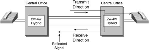
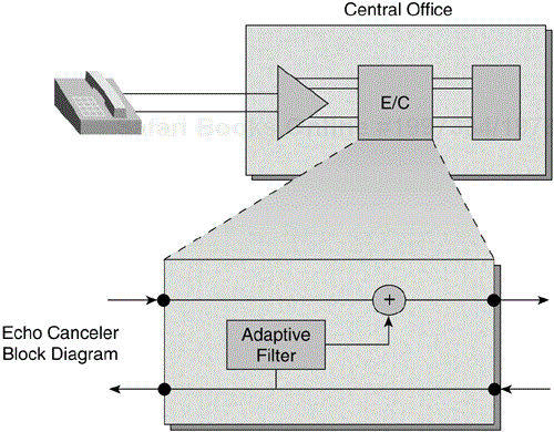
Echo is a phenomenon found in voice networks. Echo occurs when the transmitted voice is reflected back to the point from which it was transmitted. Echo is typically caused by a reflection of voice energy within a device called a hybrid, which converts a two-wire local loop copper pair to a four-wire interface for long-distance transmission. When there is an impedance mismatch between the two–wire and the four-wire interfaces, the voice energy that cannot be passed along the path of transmission is reflected back to the source (see Figure 6-15).
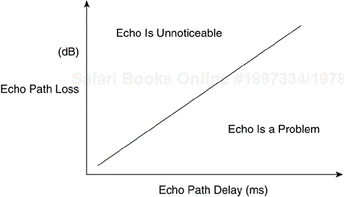
In voice networks, echo cancellation devices are used within a carrier's network when the propagation delay increases to the point where echo is made worse as a result of the combination of the reflected energy and a significant delay component of the end-to-end transmission of a voice conversation. Figure 6-16 shows echo as a function of delay and power levels.
The longer the distance of the voice transmission, the more delay is expected and the more likely that echo will result. Voice transmitted over a Frame Relay network will also face propagation delays. As the end-to-end delay increases, the echo becomes noticeable to the end user if it is not canceled (see Figure 6-17).
The bursty nature and variable frame sizes of Frame Relay may result in variable delays between consecutive packets. The variation in the time difference between each arriving packet is called jitter.
Jitter can cause the equipment at the receiving end customer's premises to have difficulty regenerating voice in a smooth and even fashion. Because voice is inherently a continuous wave form, a large gap between the regenerated voice packets will result in a distorted sound. To avoid dropping frames, data can be buffered at the speech decoder sufficiently to account for the worst-case delay variation through the network.
The application of Voice over Frame Relay networks can usually withstand infrequent packet loss better than data. If a Voice over Frame Relay packet is lost, the user will most likely not notice. If excessive frame loss occurs, it is equally unacceptable for Voice over Frame Relay and data traffic. Packet loss can occur as a result of queue overflow or when bit errors are introduced into the frame along the transmission path and the CRC (cyclic redundancy check) error-checking mechanism detects errors and drops the frame. In either case, the voice transmission can be sufficiently degraded as to be unusable.
It is necessary for Voice over Frame Relay to support fax and data modem services. Voice band fax and data modem signals can be demodulated and transmitted as digital data in packet format. This is typically referred to as fax relay, and can add efficiency to the overall support of fax traffic on a data network, without the requirement to modulate and demodulate fax over a voice channel at 64 kbps.
It is difficult, however, to reliably compress fax and data modem signals over voice channels to achieve the low-bandwidth utilization often necessary for the most efficient integration over Frame Relay. Typical Frame Relay switch interfaces use a scheme in which voice is compressed to a low bit rate, but upon detection of a fax tone, the bandwidth is reallocated to a 64 kbps rate to allow for support of higher-speed fax transmission. The typical requirement is a 64 kbps channel, supporting Group 3 fax at 14.4 kbps. If the equipment supports fax relay, the bit rate of the fax transmission remains 14.4 kbps across the entire transmission path.
Voice, fax, and some data types are delay-sensitive. This means that if the end-to-end delay or delay variation exceeds a specified limit, the service level will degrade. To minimize the potential for service degradation, one can employ a variety of mechanisms and techniques.
To minimize voice traffic delay, a prioritization mechanism that provides service to the delay-sensitive traffic first can be employed. Equipment capable of integrating Voice over Frame Relay may provide a variety of proprietary mechanisms to ensure a balance between voice and data transmission needs. These may include custom, priority, or weighted queuing. Although they may differ, the concept remains the same. For example, each input traffic type may be configured into one of several priority queues. Voice and fax traffic can be placed in the highest-priority queue, and lower-priority data traffic can be queued until the higher-priority voice and fax packets are sent.
Prioritization places delay-sensitive traffic, such as voice, ahead of lower-priority data transmissions.
Fragmentation is used to break up larger blocks of data into smaller, more predictable and manageable frames. Fragmentation attempts to ensure an even flow of voice frames into the network, minimizing delay (see Figure 6-14).
Fragmentation ensures that high-priority traffic such as voice does not have to wait to be sent. Long data packets can be interrupted to send a voice packet.
The fragmentation often affects all the data in the network to retain consistent voice quality. This is because even if the voice information is fragmented, delay will still occur if a voice frame is held up in the middle of the network behind a large data frame. This fragmentation of data packets ensures that voice and fax packets are not unacceptably delayed behind large data packets. Additionally, fragmentation reduces jitter because voice packets can be sent and received more regularly. Fragmentation, especially when used with prioritization techniques, is used to ensure a consistent flow of voice information. The objective of this technique is to enable Voice over Frame Relay technology to provide service approaching toll voice quality, while allowing the data transmission on the same network to use the remaining bandwidth efficiently.
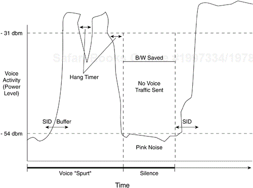
Digital speech interpolation (DSI) is also known as voice activity detection (VAD). The nature of speech communication includes pauses between words and sentences. VAD-compression algorithms, which identify and remove these periods of silence, effectively reduce the overall amount of speech information to be transmitted. DSI uses advanced voice-processing techniques to detect silent periods and suppress transmission of this information. By taking advantage of this technique, bandwidth consumption may be reduced (see Figure 6-18).
Some equipment vendors offer voice Frame Relay Access Devices (FRADs) that use different bandwidth-optimization multiplexing techniques, such as logical link multiplexing and subchannel multiplexing. Logical link multiplexing allows voice and data frames to share the same PVC, and thus enables the user to save on carrier PVC charges and to increase the utilization of the PVC.
Subchannel multiplexing is a technique used to combine multiple voice conversations within the same frame. By allowing multiple voice payloads to be sent in a single frame, packet overhead is reduced. This may offer increased performance on low-speed links. This technique can allow slow-speed connections to transport small voice packets efficiently across the Frame Relay network.
This chapter focused on the implementation of packet-switching services and addressed network design in terms of the packet-switching service topics, including hierarchical network design, topology design, broadcast issues, and performance issues. Also covered were Voice over Frame Relay networking design considerations.

