Edited by Salman Asad
As telephone companies make Integrated Services Digital Network (ISDN) services available, ISDN is becoming an increasingly popular way to connect remote sites. This case study covers the following ISDN scenarios:
Configuring DDR over ISDN—. This telecommuting scenario describes the configuration of home sites that use ISDN to connect to a central company network and shows you how to use calling line identification numbers to prevent unauthorized access to the central network.
Configuring Snapshot Routing over ISDN—. Snapshot routing provides cost-effective access to a central company network from branch or home offices. Snapshot routing is used to upgrade the telecommuting network and control routing updates in Novell IPX networks.
Configuring AppleTalk over ISDN—. This scenario shows you how to control AppleTalk packets that might otherwise trigger unnecessary ISDN connections.
Configuring IPX over ISDN—. This scenario shows you how to configure IPX as a Layer 3 protocol for ISDN.
In the United States, many companies today regard telecommuting as a way to solve space problems, conform to the Clean Air Act, and make employees more productive. In Europe, companies are looking for solutions that allow central offices to connect to remote sites. In the past, analog modems provided the necessary connectivity over serial lines, but they are not fast enough for LAN-to-LAN connections or for remote use of graphics programs, such as computer-aided design (CAD) tools. ISDN provides the needed additional bandwidth without requiring a leased line.
AnISDN Basic Rate Interface (BRI) provides two 64-kbps B channels for voice or data, and one 16-kbps D channel for signaling. Voice and data information is carried over the B channels digitally. In the United States, ans ISDN Primary Rate Interface (PRI) provides 23 64-kbps B channels for voice and data over a T1 connection, and one 64-kbps D channel for signaling. In Europe, a PRI provides 30 B channels for voice and data, and one D channel for signaling over an E1 connection.
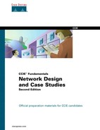
Figure 21-1 shows the network that will be discussed in this case study. The ISDN network uses multiple central-office ISDN switches
In this case study, the remote sites (homes) use Cisco 2503 routers, which provide one BRI, an Ethernet interface, and two high-speed serial interfaces. At the central company site, a Cisco 7000 series router equipped with a channelized T1 card answers the calls. The channelized T1 card provides a PRI.
Currently, in many parts of the United States, telephone companies have not deployed Signaling System 7, which means that calls between certain central offices must be placed at 56 kbps. This restriction does not apply to all parts of the United States or to other countries, but it does apply to some of the sample ISDN networks described in this chapter.
If you are using an external ISDN terminal adapter, also known as an ISDN modem, you can use the configuration examples provided in Chapter 19, "Dial-on-Demand Routing." Although an ISDN modem provides ISDN connectivity and enables you to use existing serial interfaces, it is not always the optimal solution because of the investment in an external unit and in additional cabling. Also, using V.25bis does not give the router full access to certain information available in an ISDN network, such as the speed of the call or the number of the calling party.
The native ISDN interface on the Cisco 2503 router allows the router to be directly connected to an ISDN NT1 device. In many countries, the NT1 is provided by the telephone company. In the United States, however, the NT1 is customer-owned equipment. By directly connecting to the ISDN network, the router has more direct control over ISDN parameters and has access to ISDN information.
Configuring a native ISDN interface is similar to configuring a serial interface using DDR routing, as described in Chapter 19. There are, however, two major differences:
The dialer in-band command is not required with ISDN. PRI and BRI interfaces are assumed by the router to be a DDR interface.
The individual B channels cannot be configured separately, unless you are using the dialer profile feature of the Cisco IOS. The B channels of a BRI appear to be a dialer rotary group with two members. In the United States, the B channels of a PRI appear to be a dialer rotary group with 23 members, and in Europe, the B channels of a PRI appear to be a dialer rotary group with 30 members. Because the PRI or BRI is a dialer rotary group, all configuration commands associated with a PRI or BRI apply to all B channels.
The following sections describe the configurations of the central-site and home-site routers. In this case study, both the central site and the home sites can place calls. The central site uses a Cisco 7000 router that connects to a Nor Tel DMS-100 central-office ISDN switch. One remote-site router (nick-isdn) connects to the same central-office switch that the central-site router uses. Connections from the other remote-site router (dave-isdn) pass through two central-office switches to reach the central-site router.
Two remote-site users, Dave and Nick, dial from their homes in to the central-site router that is configured as follows. Part of the configuration of the central-site router is specific to the DMS-100 switch, whereas other commands apply to any type of ISDN central-office switch.
  hostname central-isdn
  !
  username dave-isdn password 7 130318111D
  username nick-isdn password 7 08274D02A02
  isdn switch-type primary-dms100
  !
  interface ethernet 0
  ip address 11.108.40.53 255.255.255.0
  no mop enabled
  !
  controller t1 1/0
  framing esf
  linecode b8zs
  pri-group timeslots 2-6
  !
  interface serial 1/0:23
  ip address 11.108.90.53 255.255.255.0
  encapsulation ppp
  dialer idle-timeout 300
  dialer map ip 11.108.90.1 name dave-isdn speed 56 914085553680
  dialer map ip 11.108.90.7 name nick-isdn 8376
  dialer-group 1
  ppp authentication chap
  !
  router igrp 10
  network 11.108.0.0
  redistribute static
  !
  ! route to nick-isdn
  ip route 11.108.137.0 255.255.255.0 11.108.90.7
  ! route to dave-isdn
  ip route 11.108.147.0 255.255.255.0 11.108.90.1
  !
  !NTP
  access-list 101 deny udp 0.0.0.0 255.255.255.255 0.0.0.0 255.255.255.255 eq 123
  !SNMP
  access-list 101 deny udp 0.0.0.0 255.255.255.255 0.0.0.0   255.255.255.255 eq 161
  access-list 101 permit ip 0.0.0.0 255.255.255.255 0.0.0.0 255.255.255.
  !
  dialer-list 1 list 101
The configurationbegins by establishing the host name of the router. The username commands establish the names of the routers allowed to dial up this router. The names correspond to the host names of Dave's router and Nick's router. The isdn switch-type command specifies that the central-site router connects to a NorTel DMS-100 switch. The host name, usernames, and ISDN switch type vary from router to router.
The controller command uses t1 to specify a T1 controller interface. The "1" indicates that the controller card is located in backplane slot number 1. The "0" indicates port 0.
The framing command selects the frame type for the T1 data line. In this case, the framing command uses the esf keyword to indicate the extended super frame (ESF) frame type. The service provider determines which framing type, either sf, esf, or crc4, is required for your T1/E1 circuit.
The linecode command defines the line-code type for the T1 data line. In this case, the linecode command uses the b8zs keyword to indicate that the line-code type is bipolar 8 zero substitution (B8ZS). The service provider determines which line-code type, either alternate mark inversion (AMI) or B8ZS, is required for your T1/E1 circuit.
The pri-group controller configuration command specifies an ISDN PRI on a channelized T1 card in a Cisco 7000 series router. The timeslots keyword establishes the B channels. In this example, only five B channels (channels 2 through 6) are in use on this controller.
The ip address command establishes the IP address of the interface, and the encapsulation ppp command establishes the Point-to-Point Protocol (PPP) as the encapsulation method. PPP supports Challenge Handshake Authentication Protocol (CHAP) and Password Authentication Protocol (PAP) as authentication mechanisms for identifying the caller and providing a level of security. The dialer idle-timeout command sets the idle timeout to five minutes.
The dialer map commands establish the remote sites that the router can call. Because Dave's router connects to a central-office switch that does not use Signaling System 7, the dialer map command for calling Dave's router uses the speed keyword, which is valid for native ISDN interfaces only. The native ISDN interface on the Cisco 2503 operates at either 64 or 56 kbps. If the calling party and the called party use the same ISDN switch, they can communicate at 64 kbps. Otherwise, they must communicate at 56 kbps.
Because Nick's ISDN line connects to the same central office as the line that the central-site router uses, the telephone number in the dialer map command for connecting to Nick's router does not have to include the three-digit prefix. Note that because the central-site router uses lines that are part of a Centrex, the outgoing telephone numbers start with 9 if they are not four-digit numbers.
The dialer-group command associates the BRI with dialer access group 1. The ppp authentication chap command enables CHAP authentication.
In the routing section of the configuration, the router igrp command enables the Interior Gateway Routing Protocol (IGRP) and sets the autonomous system number to 10. The network command assigns the network number. The redistribute command sends the static route information (defined with the ip route commands) to other routers in the same IGRP area. Without this command, other routers connected to the central site would not have routes to the remote routers.
DDR tends to use static routes extensively because routing updates are not received when the dialup connection is not active. The first two ip route commands create the static routes that define the subnets that Dave and Nick use.
Note
The IGRP commands are the same on all central-site routers, except that the static routes correspond to the home sites calling in to each central-site router.
DDR uses access lists to determine whether a packet is interesting or uninteresting. Interesting packets cause a call to be placed if a call is not active, or cause a call that has already been placed to be maintained as active. The first extended access-list command states that IGRP updates are uninteresting. The second extended access-list command states that Network Time Protocol (NTP) packets are uninteresting. The third extended access-list command specifies that Simple Network Management Protocol (SNMP) packets are uninteresting, and the final extended access-list command states that all other IP packets are interesting. The dialer-list command assigns the set of access lists to dialer access group 1.
The configurations of the home-site routers are similar, but Nick's configuration is simpler because his router connects to the same central-office switch as the central-site router.
The configuration for the router at Nick's home is as follows:
  hostname nick-isdn
  !
  username central-isdn password 7 050D130C2A5
  isdn switch-type basic-dms100
  !
  interface ethernet 0
  ip address 11.108.137.1 255.255.255.0
  no mop enabled
  !
  interface bri 0
  ip address 11.108.90.7 255.255.255.0
  encapsulation ppp
  no ip route-cache
  isdn spid1 415555837601 5558376
  isdn spid2 415555837802 5558376
  dialer idle-timeout 300
  dialer map ip 11.108.90.53 name central-isdn 8362
  dialer map ip 11.108.90.53 name central-isdn 8370
  dialer-group 1
  ppp authentication chap
  !
  ip route 11.108.0.0 255.255.0.0 11.108.90.53
  !
  access-list 101 deny udp 0.0.0.0 255.255.255.255 0.0.0.0 255.255.255.255 eq 177
  access-list 101 permit ip 0.0.0.0 255.255.255.255 0.0.0.0 255.255.255.255
  !
  dialer-list 1 list 101
As with the central-site router, the isdn switch-type command specifies that the switch is an NT DMS-100 switch. Because Nick's router connects to the DMS-100, service profile identifiers (SPIDs) are required for the BRI. PPP and CHAP are configured, along with a username command for the central-site router. The configuration for Nick's router differs from that of the central site with regard to the dialer map commands and the routing section. Two dialer map commands point to the same next-hop address. If the attempt to call the first number fails, the second number will be used to connect to the next-hop address.
The isdn spid1 and isdn spid2 commands represent SPIDs. SPIDs are used when a BRI connects to a NorTel DMS-100 switch or to a National ISDN-1 switch. SPIDs are assigned by the service provider to associate a SPID number with a telephone number. Other switch types do not require SPIDs. Your service provider can tell you whether SPIDs are required for your switch. In this example, SPID 1 identifies 415 as the area code, 555 as the exchange, 8376 as the station ID, and 01 as the terminal identifier. The SPID format required by your service provider may differ from the examples shown in this case study.
The configuration for Dave's router is similar to the configuration for Nick's router, except that Dave's router is not in the same Centrex as the central company site. The configuration for Dave's router is as follows:
  hostname dave-isdn
  !
  username central-isdn password 7 08274341
  isdn switch-type basic-5ess
  !
  interface ethernet 0
  ip address 11.108.147.1 255.255.255.0
  no mop enabled
  !
  interface bri 0
  ip address 11.108.90.1 255.255.255.0
  encapsulation ppp
  no ip route-cache
  bandwidth 56
  dialer map ip 11.108.90.53 name central-isdn speed 56 14155558370
  dialer-group 1
  ppp authentication chap
  !
  ip route 11.108.0.0 255.255.0.0 11.108.90.53
  !
  dialer-list 1 list 101
Dave's configuration is different from Nick's configuration because Dave's router connects to an AT&T 5ESS central-office ISDN switch that does not run Signaling System 7. The isdn switch-type command specifies a basic rate AT&T switch, which does not require Dave's router configuration to use the isdn spid1 and isdn spid2 commands that the DMS-100 switch requires. The bandwidth interface configuration command tells routing protocols that the line operates at 56 kbps. The dialer map command uses the speed keyword so that when Dave's router dials up the central-site router, it sets the line speed to 56 kbps. This setting is necessary when the connection traverses a switch that does not run Signaling System 7.
Because Nick is in the same Centrex as the central company routers, the central router can use the calling line identification (CLID) number received from the ISDN switch to identify Nick. With CLID, the configuration for Nick does not require CHAP or PAP; however, Nick needs to modify his configuration to include CLID. Nick's new configuration and a sample of the central-site changed configuration are shown in the following sections.
Note
CLID is not available in all parts of the United States and other countries. Some countries do not require Centrex for CLID.
Here is the central-site PRI interface configuration modified for CLID:
  controller t1 1/0
  framing esf
  linecode b8zs
  pri-group timeslots 2-6
  !
  interface serial 1/0:23
  ip address 11.108.90.53 255.255.255.0
  dialer idle-timeout 300
  dialer map ip 11.108.90.7 name 5558376 8376
  dialer-group 1
The name keyword in the dialer map command specifies the actual string that calling line identification returns. This string differs from the number called: The number called is a four-digit Centrex number, and the number returned is the full seven digits.
As with the central site, the major difference in Nick's configuration is the use of the name keyword with the dialer map command that specifies the actual number being returned as the calling line number.
  interface bri 0
  ip address 11.108.90.7 255.255.255.0
  no ip route-cache
  isdn spid1 415555837601 5558376
  isdn spid2 415555837802 5558378
  dialer idle-timeout 300
  dialer map ip 11.108.90.53 name 5558362 8362
  dialer map ip 11.108.90.53 name 5558370 8370
  dialer-group 1
Because Dave is located several miles from the central office, calls to the central-office router are metered and billed to Dave's telephone number. The callback feature (introduced in Cisco IOS 11.0) allows Dave's router to place a call to the central-site router, requesting that the central-site router call Dave's router. Then, the central-site router disconnects the call and places a return call to Dave's router. With callback configured, Dave's telephone bill is reduced because actual data transfers occur when the central-office router calls back. The following commands configure callback on Dave's router:
  interface bri 0
  ppp callback request
  dialer hold-queue 100 timeout 20
The ppp callback command with the request keyword specifies that when the interface places a call, it is to request callback. The dialer hold-queue interface configuration command specifies that up to 100 packets can be held in a queue until the central-site router returns the call. If the central-site router does not return the call within 20 seconds plus the length of the enable timeout configured on the central-site router, the packets are dropped. The following commands configure callback on the central office router:
  map-class dialer class1
  dialer callback-server username
  interface serial 1/0:23
  dialer map ip 11.108.90.1 name dave-isdn speed 56 class class1 914085553680
  ppp callback accept
  dialer callback-secure
  dialer enable-timeout 1
  dialer hold-queue
The map-class command establishes a quality of service (QoS) parameter to be associated with a static map. The dialer keyword specifies that the map is a dialer map. The class1 parameter is a user-defined value that creates a map class to which subsequent encapsulation-specific commands apply.
The dialer map interface configuration command has been modified to include the class keyword and the name of the class, as specified in the map-class command. The name keyword is required so that, when Dave's router dials in, the interface can locate this dialer map statement and obtain the dial string for calling back Dave's router.
The ppp callback command with the accept keyword allows the interface to accept and honor callback requests that come into the interface. (Callback depends on PPP authentication, using PAP or CHAP.)
The dialer callback-server command allows the interface to return calls when callback is successfully negotiated. The username keyword specifies that the interface is to locate the dial string for making the return call by looking up the authenticated host name in a dialer map command.
The dialer callback-secure command specifies that the router is to disconnect the initial call, and to call back only if it has a dialer map command with a defined class for the remote router. If the dialer callback-secure command is not present, the central router will not drop the connection if it does not have a dialer map command with a defined class. The dialer enable-timeout interface configuration command specifies that the interface is to wait one second after disconnecting the initial call before making the return call.
Snapshot routing is an easy way to reduce connection time in ISDN networks by suppressing the transfer of routing updates for a configurable period of time. Snapshot routing is best suited for networks whose data-transfer connections typically last longer than five minutes and that are running the following distance vector protocols:
Routing Information Protocol (RIP) and Integrated Gateway Routing Protocol (IGRP) for IP
Routing Table Maintenance Protocol (RTMP) for AppleTalk
Routing Information Protocol (RIP) and Service Advertisement Protocol (SAP) for Novell Internet Packet Exchange (IPX)
Routing Table Protocol (RTP) for Banyan VINES
The goal of snapshot routing is to allow routing protocols to exchange updates as they normally would. Because Enhanced IGRP and link-state routing protocols, such as Novell Link Services Protocol (NLSP), Open Shortest Path First (OSPF), and Intermediate System-to-Intermediate System (IS-IS) depend on the frequent sending of hello messages to neighboring routers to discover and maintain routes, they are incompatible with snapshot routing.
Note
This case study applies snapshot routing to an ISDN network; other similar media, however, such as dedicated leased lines, can benefit from the reduction of periodic updates that snapshot routing provides.
Before snapshot routing became available in Cisco Internetwork Operating System (IOS) Software Release 10.2, ISDN interfaces were configured using static routes. Static routes, such as the routes defined by the ip route commands in the Central Site section earlier in this chapter, prevent bandwidth from being consumed by routing updates, but they are difficult to maintain as the network grows.
Snapshot routing supports dynamic routes by allowing routing updates to occur during an active period and reduces connection cost by suppressing routing updates during a quiet period, which can be up to 65 days long. During the quiet period, the routing tables on the routers at both ends of a link are frozen. shows the relationship of active and quiet periods over time
During the active period, the routers at each end of the connection exchange the routing updates that are normal for their configured routing protocols. They continue to exchange routing updates until the active period ends. When the active period ends, each router freezes its routing tables, stops sending routing updates, and enters the quiet period. Each router remains in the quiet period until a configurable timer expires, at which time one of the routers initiates a connection to send and receive routing updates.
To ensure that routing tables are updated, the active period must be long enough for several routing updates to come through the link. An active period that is too short might allow only one routing update to cross the link. If that update is lost due to noise on the line, the router on the other end would age out a valid route or would not learn about a new valid route. To make sure that updates occur, the active period must be at least five minutes long (that is, three times longer than the routing protocols'update intervals). Because the routing protocols update their routing tables during the active period as they normally would, there is no need to adjust any routing protocol timers.
If the line is not available when the router transitions from the quiet period to the active period, it enters a retry period. During the retry period, the router continually attempts to connect until it enters an active period, as shown in Figure 21-3.
Table 21-1 shows the minimum and maximum lengths of each period.
Table 21-1. Snapshot Routing Periods
| Period | Configurable | Minimum Length | Maximum Length |
|---|---|---|---|
| Active | Yes | 5 minutes | 100 minutes |
| Quiet | Yes | 5 minutes | 65 days |
| Retry | No | 8 minutes | 8 minutes |
By default, snapshot routing allows routing updates to be exchanged over connections established to transfer user data. This means that, if necessary, snapshot routing forces the connection to last as long as the active period. If you do not want the routers to exchange updates during connections established to transfer user data, use the suppress-statechange-updates keyword.
Snapshot routing is well suited to the hub-and-spoke topology of the telecommuting network described in the Configuring DDR over ISDN section at the beginning of this chapter. Snapshot routing is designed for a client/server relationship. The client routers, such as the home sites, determine the frequency at which the routers exchange updates by setting the length of the quiet period, and the server router accepts incoming snapshot connections from several client routers.
Note
Snapshot routing is not recommended for meshed topologies. In meshed topologies, configuring static routes is more efficient than configuring snapshot routing.
The following is the configuration of the central-site router after modification for snapshot routing:
  hostname central-isdn
  !
  username dave-isdn password 7 130318111D
  username nick-isdn password 7 08274D02A02
  isdn switch-type primary-dms100
  !
  interface ethernet 0
  ip address 11.108.40.53 255.255.255.0
  no mop enabled
  !
  controller t1 1/0
  framing esf
  linecode b8zs
  pri-group timeslots 2-6
  ip address 11.108.90.53 255.255.255.0
  encapsulation ppp
  dialer idle-timeout 300
  dialer map ip 11.108.90.1 name dave-isdn speed 56 914085553680
  dialer map ip 11.108.90.7 name nick-isdn 8376
  dialer-group 1
  isdn spid1 415555836201 5558362
  isdn spid2 415555837002 5558370
  snapshot server 5
  ppp authentication chap
  !
  router igrp 10
  network 11.108.0.0
  redistribute static
  !
  ! route to nick-isdn
  ip route 11.108.137.0 255.255.255.0 11.108.90.7
  ! route to dave-isdn
  ip route 11.108.147.0 255.255.255.0 11.108.90.1
  !
  access-list 101 deny igrp 0.0.0.0 255.255.255.255 0.0.0.0 255.255.255.255
  !NTP
  access-list 101 deny udp 0.0.0.0 255.255.255.255 0.0.0.0 255.255.255.255 eq 123
  !SNMP
  access-list 101 deny udp 0.0.0.0 255.255.255.255 0.0.0.0 255.255.255.255 eq 161
  access-list 101 permit ip 0.0.0.0 255.255.255.255 0.0.0.0 255.255.255.255
  !
  dialer-list 1 list 101
The ip route commands that configured static routes for the home sites have been removed from the configuration. The snapshot server command enables snapshot routing. The "5" sets the length of the active period to five minutes.
The following is the configuration of Dave's home-site router after modification for snapshot routing:
  hostname dave-isdn
  !
  username central-isdn password 7 08274341
  isdn switch-type basic-5ess
  !
  interface ethernet 0
  ip address 11.108.147.1 255.255.255.0
  no mop enabled
  !
  interface bri 0
  ip address 11.108.90.1 255.255.255.0
  encapsulation ppp
  no ip route-cache
  bandwidth 56
  dialer map snapshot 1 name central-isdn 14155558370
  dialer map ip 11.108.90.53 name central-isdn speed 56 14155558370
  dialer-group 1
  snapshot client 5 43200 suppress-statechange-updates dialer
  ppp authentication chap
  !
  dialer-list 1 list 101
The ip route commands that configured static routes for the home sites have been removed from the configuration. The dialer map snapshot command establishes a map (whose sequence number is 1) that the router uses to connect to the central-site router for the exchange of routing updates. The name keyword specifies the name of the remote router associated with the dial string. Because the ppp authentication interface configuration command enables CHAP authentication, when this router dials the central router, it receives the host name of the central router and compares it with the name specified by the name keyword.
The snapshot client command sets the length of the active period to five minutes (a value that must match the value set in the snapshot server's configuration) and sets the length of the quiet period to 43,200 seconds (12 hours). The suppress-statechange-updates keyword prevents the routers from exchanging updates during connections established to transfer user data. The dialer keyword allows the client router to dial up the server router in the absence of regular traffic, and is required when you use the suppress-statechange-update keyword.
This section describes a Novell IPX network for which snapshot routing has been configured. Client routers at branch offices use DDR to connect to a central router over ISDN. At the central office, NetWare servers use the Novell IPX protocol to provide services to NetWare clients on each branch office network. Some client-to-server connections are required during a limited period of the day. figure 21-4 illustrates the network
In this topology, the client routers are responsible for updating their routing tables by connecting to the server router when the quiet period expires. The client routers also retrieve update information if a reload occurs.
Note
Snapshot routing works with Novell 3.x and 4.x networks. However, Novell 4.x includes a time-synchronization protocol that causes Novell 4.x time servers to send an update every 10 minutes. To prevent the time server from generating update packets that would cause unwanted connections, you should load a NetWare Loadable Module (NLM) named TIMESYNC.NLM, which enables you to increase the update interval for these packets to several days. A similar problem is caused by Novell's efforts to synchronize NDS replicas. NetWare 4.1 includes two NLMs, DSFILTER.NLM and PINGFILT.NLM, which work together to control NDS synchronization updates. You should use these two modules to make sure that NDS synchronization traffic is sent to specified servers only at the specified times.
The following is the complete configuration for the server router:
  hostname RouterA
  !
  username RouterB password 7 120DOA031D
  username RouterC password 7 111D161118
  username RouterD password 7 43E7528384
  isdn switch-type vn3
  !
  ipx routing

  interface Ethernet 0
  ip address 192.104.155.99 255.255.255.0
  ipx network 300
  !
  interface bri 0
  ip address 1.0.0.1 255.0.0.0
  encapsulation ppp
  ipx network 10
  no ipx route-cache
  ipx update-time 20
  ipx watchdog-spoof
  dialer idle-timeout
  dialer wait-for-carrier-time 12
  dialer map ipx 10.0000.0000.0002 name RouterB broadcast 041389082
  dialer map ipx 10.0000.0000.0003 name RouterC broadcast 041389081
  dialer map ipx 10.0000.0000.0004 name RouterD broadcast 041389083
  !
  dialer-group 1
  snapshot server 10
  ppp authentication chap
  !
  access-list 901 deny 0 FFFFFFF 0 FFFFFFFF 457
  access-list 901 deny 1 10.0000.0000.0001 0 10.ffff.ffff.ffff 453
  access-list 901 deny 4 10.0000.0000.0001 0 l0.ffff.ffff.ffff 452
  access-list 901 deny 4 FFFFFFFF 0 FFFFFFFF 456
  access-list 901 permit -1
  !
  dialer-list 1 list 901
The configuration begins with the host name used for CHAP authentication. The usernames correspond to the host names of Router B, Router C, and Router D. The isdn switch-type command specifies that the router connects to a French VN3 ISDN BRI switch.
The dialer idle-timeout command specifies 60 seconds as the amount of idle time that must elapse before the router disconnects the line. The dialer wait-for-carrier-time command sets the wait-for-carrier time to 60 seconds.
The first dialer map command sets the next-hop address of Router B to 10.0000.0000.0002. When Router B dials up the server router (Router A), the server router uses the next-hop address to transmit packets to Router B. The broadcast keyword sets 041389082 as the address to which IPX broadcasts are to be forwarded. The second and third dialer map commands set similar values for Router C and Router D.
The snapshot server command sets the length of the active period to 10 minutes. The ppp authentication command sets CHAP as the authentication protocol.
Access lists are used to determine whether an outgoing packet is interesting or uninteresting. Uninteresting packets are dropped, and interesting packets cause a call to be placed if a call is not active, or cause a call that has already been placed to be maintained as active. The access lists defined by this configuration are extended Novell IPX access lists. The first access-list command defines any packets intended for the Novell serialization socket as uninteresting. The second access-list command defines RIP packets as uninteresting. The third access-list command defines SAP packets as uninteresting. The fourth access-list command defines Novell diagnostic packets generated by the Autodiscovery feature as uninteresting, and the final access-list command states that all other packets are interesting. The dialer-list global configuration command assigns access list 901 to dialer access group 1, which is associated with BRI 0 by the dialer-group interface configuration command.
The configurations for the client routers are the same except for the commands that configure the router's host name, the username that it uses when it dials up Router A, and the router's network numbers. The following is the configuration for Router B:
  hostname RouterB
  !
  username RouterA password 7 105A060D0A
  ipx routing
  isdn switch-type vn3
  isdn tei first-call
  !
  interface ethernet 0
  ip address 192.104.155.100 255.255.255.0
  ipx network 301
  !
  interface bri 0
  no ip address
  encapsulation ppp
  ipx network 10
  no ipx route-cache
  ipx update-time 20
  ipx watchdog-spoof
  dialer idle-timeout 60
  dialer wait-for-carrier-time 12
  dialer map snapshot 1 name RouterA 46148412
  dialer map ipx 10.0000.0000.0001 name RouterA broadcast 46148412
  dialer-group 1
  snapshot client 10 86400 dialer
  ppp authentication chap
  !
  access-list 901 deny 0 FFFFFFFF 0 FFFFFFFF 457
  access-list 901 deny 1 10.0000.0000.0002 0 10.ffff.ffff.ffff 453
  access-list 901 deny 4 10.0000.0000.0002 0 10.ffff.ffff.ffff 452
  access-list 901 deny 4 FFFFFFFF 0 FFFFFFFF 456
  access-list 901 permit 0
  !
  dialer-list 1 list 901
The configuration begins with the host name used for CHAP authentication. The usernames correspond to the host names of Router B, Router C, and Router D. The isdn switch-type command specifies that the router connects to a French VN3 ISDN BRI switch.
The isdn tei global configuration command uses the first-call keyword to specify that ISDN terminal endpoint identifier (TEI) negotiation is to occur when Router A places or receives its first ISDN call. (The default is for TEI negotiation to occur when the router is powered on.)
The dialer wait-for-carrier interface configuration command specifies 12 seconds as the number of seconds that the interface will wait for the carrier to come up when it places a call.
The snapshot client interface configuration command sets the length of the active period to 10 minutes (a value that must match the value set in the snapshot server's configuration), and sets the length of the quiet period to 86,400 seconds (24 hours). Because the suppress-statechange-updates keyword is not used, the routers can exchange updates during connections established to transfer user data. The dialer keyword allows the client router to dial up the server router in the absence of regular traffic.
To run AppleTalk over an ISDN network effectively, you need to prevent Name Binding Protocol (NBP) packets and RTMP updates from triggering unnecessary connections over ISDN connections.
Figure 21-5 shows a sample AppleTalk network that uses ISDN to connect two networks located in different cities. Users on the district-office network occasionally need access to servers located on the main-office network and vice versa. In this scenario, both routers dial up each other when user data from one part of the network needs to reach the other part of the network.
Users of hosts connected to the main-office network do not need to access the Training zone, so when configuring Router A, one goal is to prevent NBP packets generated by the Training zone from triggering an ISDN connection with the main-office network. Another configuration goal for both routers is to prevent NBP packets generated by the printers on each network from triggering an ISDN connection.
To control the forwarding of NBP packets, use AppleTalk-style access lists. AppleTalk-style access lists enable you to control the flow of NBP packets based on the type of the entity that originated the packet, the name of the entity that originated the packet, and the zone of the entity that originated the packet.
Note
The capability to control the forwarding of NBP packets was introduced in Cisco IOS Software Release 11.0.
Both routers also need to control RTMP packets. To control RTMP packets, configure static AppleTalk cable ranges and node numbers, and use the no appletalk send rtmps command on the ISDN BRI or PRI interface that connects two AppleTalk networks.
As shown in Figure 21-5,Router A is located in the district office. The district-office network consists of two zones: Sales and Training. On Router A, an AppleTalk-style access list is assigned to BRI 0 to prevent the forwarding of NBP packets that come from printers and NBP packets that come from the Training zone. If the router were to allow the forwarding of these packets, they would trigger an unnecessary ISDN connection to the main-office network
  hostname RouterA
  !
  username RouterB password 7 125D063D2E
  appletalk routing
  appletalk static cable-range 20-20 to 15.43 zone Administration
  appletalk static cable-range 25-25 to 15.43 zone Marketing
  isdn switch-type basic-ni1
  !
  interface ethernet 0
  appletalk cable-range 5-5 5.128
  appletalk zone Sales
  !
  interface ethernet 1
  appletalk cable-range 10-10 10.26
  appletalk zone Service
  !
  interface bri 0
  appletalk static cable-range 15-15 15.42
  appletalk zone PhoneZone
  no appletalk send-rtmps
  encapsulation ppp
  ppp authentication chap
  dialer idle-timeout 240
  bandwidth 56
  dialer map appletalk 15.43 name RouterA speed 56 912065553240
  dialer-group 1
  isdn spid1 602555463101 5554631
  !
  access-list 601 deny nbp 1 type LaserWriter
  access-list 601 deny nbp 2 zone Training
  access-list 601 permit nbp 3 zone Sales
  access-list 601 deny other-nbps
  access-list 601 permit other-access
  !
  dialer-list 1 list 601
The hostname command establishes the host name of Router A. The username command establishes the name of the router allowed to dial up Router A. The name corresponds to the host name of Router B. The password keyword indicates that the username command specifies a password. The "7" indicates that the password is encrypted using a Cisco-defined encryption algorithm. The appletalk routing command enables AppleTalk routing.
The appletalk static cable-range commands create static AppleTalk routes to the zones in the main office network. Static AppleTalk routes are required because the no appletalk send-rtmps command prevents the exchange of RTMP updates between the two networks. Without static routes, zones for the main office would not appear when users open the Chooser on hosts connected to the district-office network. The isdn switch-type command specifies that Router A connects to a National ISDN-1 switch.
The appletalk cable-range commands for each Ethernet interface establish the network number for the cable segment to which the interface connects and the node number of the interface. For each interface, the appletalk zone command establishes the zone name for the network connected to the interface. None of the interface configurations specifies an AppleTalk routing protocol, so the interfaces use the default routing protocol, RTMP.
The no appletalk send-rtmps interface configuration command prevents Router A from sending RTMP updates out on interface BRI 0. To compensate for the lack of RTMP exchange, you must configure static AppleTalk routes (using the appletalk static cable-range command).
The encapsulation ppp command specifies PPP encapsulation, and the ppp authentication chap command enables CHAP authentication. The dialer idle-timeout command sets the idle timeout to 240 seconds (four minutes). The bandwidth command tells routing protocols that the line operates at 56 kbps.
The dialer map command establishes the remote site that Router A is to call. In this case, the dialer map command establishes 15.43 as the next-hop address. The name keyword specifies the name of the remote router associated with the dial string. The speed keyword specifies that Router A is to set the line's rate to 56 kbps, which is required when the connection traverses a switch that does not support Signaling System 7. The dialer-group command associates the interface BRI 0 with dialer access group 1.
The isdn spid1 commands represent SPIDs and are required by National ISDN-1 switches. Service providers assign SPIDs to associate a SPID number with a telephone number. Your service provider can tell you whether SPIDs are required for your switch. In this example, SPID 1 identifies 602 as the area code, 555 as the exchange, 4631 as the station ID, and 01 as the terminal identifier.
The first access-list nbp command defines access list 601 and prevents the forwarding of NBP packets generated by any LaserWriter printer on the district-office network. The second access-list nbp command prevents the forwarding of NBP packets generated by the Training zone. The third access-list nbp command allows the forwarding of NBP packets generated by the Sales zone.
The access-list other-nbps global configuration command prevents the forwarding of all other NBP packets that have not been explicitly permitted or denied by previous access-list nbp global configuration commands.
The access-list other-access command permits all other access checks that would otherwise be denied because they are not explicitly permitted by an access-list command. The dialer-list command assigns the access list 601 to dialer access group 1, which is associated with BRI 0.
As shown in Figure 21-5, Router B is located in the main office. The main-office network consists of two zones: Marketing and Administration. With the exception of the OpenReqs server in the Administration zone, users of hosts connected to the district-office network do not need to access servers located in the Administration zone. Like the district-office network, each zone in the main-office network has its own printer, so there is no need for Router B to forward NBP packets that the printers originate. The access list for Router B prevents NBP packets that come from printers and NBP packets that come from all servers in the Administration zone (except OpenReqs) from triggering an ISDN connection to the district-office network
  hostname RouterB
  !
  username RouterA password 7 343E821D4A
  appletalk routing
  appletalk static cable-range 5-5 to 15.42 zone Sales
  appletalk static cable-range 10-10 to 15.42 zone Training
  isdn switch-type basic-5ess
  !
  interface ethernet 0
  appletalk cable-range 20-20 20.5
  appletalk zone Administration
  !
  interface ethernet 1
  appletalk cable-range 25-25 25.36
  appletalk zone Marketing
  !
  interface bri 0
  appletalk static cable-range 15-15 15.43
  appletalk zone PhoneZone
  no appletalk send-rtmps
  encapsulation ppp
  ppp authentication chap
  dialer idle-timeout 240
  bandwidth 56
  dialer map appletalk 15.42 name RouterB speed 56 917075553287
  dialer-group 1
  !
  access-list 601 deny nbp 1 type LaserWriter
  access-list 601 permit nbp 2 object OpenReqs
  access-list 601 permit nbp 3 zone Marketing
  access-list 601 deny other-nbps
  access-list 601 permit other-access
  dialer-list 1 list 601
The configuration for Router B is similar to the configuration for Router A, with the following differences:
The isdn switch-type command specifies that Router B connects to an AT&T 5ESS central-office ISDN switch. This type of switch does not use SPID numbers, so the isdn spid1 command is not used.
The first access-list nbp command defines access list 601 and prevents the forwarding of NBP packets generated by the LaserWriter printers connected to the main-office network. The second access-list nbp command allows the forwarding of packets generated by the server OpenReqs. The third access-list nbp command configurations allows the forwarding of packets generated by the Marketing zone.
Configuring ISDN when using IPX as a Layer 3 protocol can be achieved by using the configuration examples in this section. Explanations of the network diagram and the configuration commands used are also contained in this section.
In the following network, the internal IPX address, IPX network, and IPX address on the BRI of the router have been defined, respectively. Also, the SPID numbers on the BRI have been defined.
The following information applies to the network diagramed in Figure 21-6:
| NW312 internal IPX address | 2EE67FE3.0000.0000.0001 |
| PC1/NW312 IPX network | 8022A |
| NW410 internal IPX address | 301586E0.0000.0000.0001 |
| PC2/NW410 IPX network | 8022C |
| C2503 interface B0 IPX address | 8022B.0000.0c09.509f |
| C2503 ISDN phone numbers | 4085554321 |
| 4085559876 | |
| C2503 ISDN SPIDs | 408555432101 5554321 |
| 408555987601 5559876 | |
| C4000 interface B0 IPX address | 8022B.0000.0c02.e649 |
| C4000 ISDN phone numbers | 4155551234 |
| 4155556789 | |
| C4000 ISDN SPIDs | 415555123401 5551234 |
| 415555678901 5556789 |
The following shows the configuration for the C2503 router for configuring IPX over ISDN. The configuration includes line numbers that will be referred to in the explanation section after the configuration:
   1 C2503#wr t
   2 ######
   3 Current configuration:
   4 !
   5 version 10.2
   6 !
   7 hostname C2503
   8 !
   9 enable password test
  10 !
  11 username C4000 password cisco
  12 ipx routing 0000.0c09.509f
  13 ipx gns-response-delay 1000
  14 isdn switch-type basic-dms100
  15 !
  16 interface Ethernet0
  17 ipx network 8022A
  18 ipx encapsulation SAP
  19 !
  20 interface Serial0
  21 no ip address
  22 shutdown
  23 !
  24 interface Serial1
  25 no ip address
  26 shutdown
  27 !
  28 interface BRI0
  29 encapsulation ppp
  30 bandwidth 56
  31 ipx network 8022B
  32 no ipx route-cache
  33 ipx watchdog-spoof
  34 dialer idle-timeout 300
  35 dialer map ipx 8022B.0000.0c02.e649 name C4000 speed 56 broadcast 14155551234
  36 dialer map ipx 8022B.0000.0c02.e649 name C4000 speed 56 broadcast 14155556789
  37 dialer hold-queue 5
  38 dialer load-threshold 100
  39 dialer-group 1
  40 isdn spid1 408555432101 5554321
  41 isdn spid2 408555987601 5559876
  42 ppp authentication chap
  43 !
  44 access-list 900 deny -1 FFFFFFFF 0 FFFFFFFF 452
  45 access-list 900 deny -1 FFFFFFFF 0 FFFFFFFF 453
  46 access-list 900 deny -1 FFFFFFFF 0 FFFFFFFF 457
  47 access-list 900 permit -1
  48 ipx route 8022C 8022B.0000.0c02.e649
  49 ipx route 301586E0 8022B.0000.0c02.e649
  50 !
  51 ipx sap 4 NW410 301586E0.0000.0000.0001 451 2
  52 !
  53 !
  54 dialer-list 1 list 900
  55 !
  56 line con 0
  57 line aux 0
  58 line vty 0 4
  59 password test
  60 login
  61 !
  62 end
This section contains an explanation of the C2503 router configuration by referring to the line numbers.
  C2503#wr t
  ######
  Current configuration:
  !
  version 10.2
  !
  hostname C2503
  !
  enable password test
  !
username C4000 password cisco
The username C4000 is the hostname of the remote router and is used by the dialer map command. The username is case-sensitive and must match the remote router's host name exactly.
The password, which is used by the CHAP authentication process, is case-sensitive and must match the corresponding entry on the remote router exactly.
Note
To avoid confusion, the unencrypted form of the password cisco is shown in this sample configuration. In the actual configuration, the password would appear in its encrypted form: 7 13061E010803, where 7 denotes the encryption type and 13061E010803 is the encrypted form of the password cisco. When entering or making changes to the username command, always type the password in its unencrypted form and do not enter the encryption type (7), which is set automatically.
ipx routing 0000.0c09.509f
This command enables IPX routing. The router will choose a MAC address from one of its interfaces to associate with the process, so you do not need to specify it with the command. Just enter the command ipx routing.
ipx gns-response-delay 1000
The static SAP command that follows will advertise the remote server, even when the ISDN link is not active. Therefore, it may be necessary to increase the period of time before the router replies to a workstation's Get Nearest Server (GNS) request to ensure that the local file server can respond first.
isdn switch-type basic-dms100
The ISDN switch type must match your carrier's equipment. If you change the switch type, you must reload the router for the new switch type to take effect.
  interface Ethernet
  ipx network 8022A
8022A is the network number of the local network. To determine this number, type config at the local server's console prompt and match the router=92's interface network number to the LAN protocol network number. You do not need to include the leading zeros displayed for the LAN protocol network number with this command.
ipx encapsulation SAP
This command sets the Ethernet frame type of the interface to match that of the local file server. To determine the server=92s frame type, type config at the local server's console prompt, and match the router's interface IPX encapsulation to the frame type specified.
Note
The Cisco supported frame types are as follows:
| Novell Frame Type | Cisco Encapsulation |
| Novell Ethernet_II | arpa |
| Novell Ethernet_802.3 | novell-ether |
| IEEE 802.2 | sap |
| IEEE 802.2 SNAP | snap |
  interface Serial0
  no ip address
  shutdown
  !
  interface Serial1
  no ip address
  shutdown
  !
  interface BRI0
  encapsulation ppp
PPP encapsulation is recommended over HDLC to allow use of CHAP authentication.
bandwidth 56
The default bandwidth setting for a BRI interface is 64 kbps. If you configure your dialer map statements with the speed 56 option, you should include the bandwidth statement.
ipx network 8022B
8022B is the IPX network number of the ISDN segment for both routers. This network number should be unique to your network.
no ipx route-cache
IPX route cache must be turned off when IPX watchdog spoofing is enabled.
ipx watchdog-spoof
This command enables the router to reply to the local server's watchdog packets on behalf of the remote client. Without it, the server's watchdog packets would be seen as interesting packets and would activate the ISDN link.
dialer idle-timeout 300
This command sets the number of seconds the ISDN connection will remain open if no interesting traffic is being routed. The timer is reset each time an interesting packet is forwarded.
  dialer map ipx 8022B.0000.0c02.e649 name C4000 speed 56 broadcast 14155551234
  dialer map ipx 8022B.0000.0c02.e649 name C4000 speed 56 broadcast 14155556789
The dialer map command is used with CHAP authentication to place the initial call to the remote router when interesting traffic is forwarded to the BRI interface. After the connection is active, the dialer idle-timeout command determines how long it will remain active. A dialer map statement is required for each ISDN phone number to be called. Be aware, however, that two dialer map statements pointing to the same location might activate both B channels when the use of only one channel might be desired.
The parameters for this command are as follows:
8022B.0000.0c02.e649—. The IPX address of the remote router's BRI interface. To determine this address, type show ipx interface B 0 at the remote router's console prompt.
name C4000—. The host name of the remote router. The name is case-sensitive and should match the name configured for the username command shown earlier.
speed 56—. Sets the dialer speed to 56 kbps for ISDN circuits that are not 64 kbps end-to-end, and should be included in both routers'dialer map statements. (Most installations in North America must be configured for 56 kbps.)
broadcast—. Allows the forwarding of broadcast packets. Use of the broadcast parameter does not make broadcast packets interesting, however. Unless broadcast packets are specified as interesting packets by the dialer-list command, they will only be forwarded when the ISDN link is active.
14155551234 14155556789—. The remote router's ISDN telephone numbers.
dialer hold-queue 5
This command allows interesting packets to be queued until the ISDN connection is established. It is especially useful when a NetWare login is used to activate the connection to prevent the workstation from timing out. In this example, five interesting packets will be queued.
dialer load-threshold 100
This command is used to configure bandwidth on demand by setting the maximum load before the dialer places another call through the second B channel. The load is the calculated weighted average load value for the interface, where 1 is unloaded and 255 is fully loaded. The actual load value you should configure depends on the characteristics of your particular network. In this example, the second B channel will be activated when the load reaches 39% of maximum utilization, which is 100 divided by 255.
dialer-group 1
The dialer-group 1 command enables the dialer list 1 on the BRI interface, which determines which packets will be interesting to activate the ISDN connection.
  isdn spid1 408555432101 5554321
  isdn spid2 408555987601 5559876
The isdn spid commands are used if your carrier assigns SPIDs to your ISDN lines.
  access-list 900 deny -1 FFFFFFFF 0 FFFFFFFF 452
  access-list 900 deny -1 FFFFFFFF 0 FFFFFFFF 453
  access-list 900 deny -1 FFFFFFFF 0 FFFFFFFF 457
  access-list 900 permit -1
This access list determines which IPX packets will be interesting and activate the ISDN link. The access list you should create depends on your particular network design.
The command parameters for this example are as follows:
access-list 900 deny -1 -1 0 -1 452—. This will determine all SAP packets to be uninteresting.
access-list 900 deny -1 -1 0 -1 453—. This will determine all RIP packets to be uninteresting.
access-list 900 deny -1 -1 0 -1 457—. This will determine all security packets to be uninteresting.
access-list 900 permit -1—. This will determine all other packets to be interesting.
ipx route 8022C 8022B.0000.0c02.e649
This command creates a static route to the remote router's Ethernet network via the remote router's BRI interface. This is necessary because dynamic routes are removed when the ISDN link is down.
The command parameters for this example are as follows:
8022C—. The external IPX network number of the remote network. To determine this number, type config at the remote server's console prompt and match the network number to the LAN protocol statement.
8022B.0000.0c02.e649—. The IPX address of the remote router's BRI interface. To determine this address, type show ipx interface B 0 at the remote router's console prompt.
ipx route 301586E0 8022B.0000.0c02.e649
This ipx route command creates a static route to the remote server via the remote router's BRI interface. This is required because dynamic routes are lost when the ISDN link is down.
The command parameters for this example are as follows:
301586E0—. The network portion of the remote server's internal IPX address. To determine this address, type show ipx servers at the remote router's console prompt.
8022B.0000.0c02.e649—. The IPX address of the remote router's BRI interface. To determine this address, type show ipx interface B 0 at the remote router=92's console prompt.
ipx sap 4 NW410 301586E0.0000.0000.0001 451 2
This command creates a static SAP entry for the remote server, which the local router will advertise even when the ISDN link is not active.
The command parameters for this example are as follows:
4—. SAP type (server).
NW410—. Name of SAP service.
301586E0.0000.0000.0001—. Internal IPX network and host address of remote server. To determine this address, type show ipx servers at the remote router's console prompt.
451—. Socket (port) number of remote server, which is determined by the command show ipx servers on the remote router.
2—. RIP hop count to the remote server.
dialer-list 1 list 900
This command points to access list 900, which determines which IPX packets will be interesting.
The following shows the configuration for the C4000 router for configuring IPX over ISDN. For an explanation of the commands, see the section titled "Explanation of the C2503 Configuration," earlier in this chapter. (Note that this explanation is in the context of the C2503 configuration, but the general command descriptions still apply):
   1 C4000#wr t
   2 ######
   3 Current configuration:
   4 !
   5 version 10.2
   6 !
   7 hostname C4000
   8 !
   9 enable password test
  10 !
  11 username C2503 password cisco
  12 ipx routing 0000.0c02.e649
  13 ipx gns-response-delay 1000
  14 isdn switch-type basic-dms100
  15 !
  16 interface Ethernet0
  17 ipx network 8022C
  18 ipx encapsulation SAP
  19 !
  20 interface Serial0
  21 no ip address
  22 shutdown
  23 !
  24 interface Serial1
  25 no ip address
  26 shutdown
  27 !
  28 interface BRI0
  29 encapsulation ppp
  30 bandwidth 56
  31 ipx network 8022B
  32 no ipx route-cache
  33 ipx watchdog-spoof
  34 dialer idle-timeout 300
  35 dialer map ipx 8022B.0000.0c09.509f name C2503 speed 56 broadcast   14085554321
  36 dialer map ipx 8022B.0000.0c09.509f name C2503 speed 56 broadcast   14085559876
  37 dialer hold-queue 5
  38 dialer load-threshold 100
  39 dialer-group 1
  40 isdn spid1 415555123401 5551234
  41 isdn spid2 415555678901 5556789
  42 ppp authentication chap
  43 !
  44 access-list 900 deny -1 FFFFFFFF 0 FFFFFFFF 452
  45 access-list 900 deny -1 FFFFFFFF 0 FFFFFFFF 453
  46 access-list 900 deny -1 FFFFFFFF 0 FFFFFFFF 457
  47 access-list 900 permit -1
  48 ipx route 8022A 8022B.0000.0c09.509f
  49 ipx route 2EE67FE3 8022B.0000.0c09.509f
  50 !
  51 ipx sap 4 NW312 2EE67FE3.0000.0000.0001 451 2
  52 !
  53 !
  54 dialer-list 1 list 900
  55 !
  56 line con 0
  57 line aux 0
  58 line vty 0 4
  59 password test
  60 login
  61 !
  62 end
When you configure ISDN, controlling packets that trigger unnecessary connections is a major concern. In the past, one way to control routing update packets was to configure static routes. Snapshot routing and NBP-packet filtering provide new ways to control routing updates. Snapshot routing enables you to configure the network so that routed protocols update their routing tables dynamically without triggering frequent and costly ISDN connections. Snapshot routing is ideally suited for relatively stable networks in which a single router is a central point through which routing updates flow. Configuring ISDN in an IPX environment was also covered in this chapter.