Edited by Ron McCarty
This chapter describes current Asynchronous Transfer Mode (ATM) technology that network designers can use in their networks today, as well as future ATM technology to watch. This chapter also covers implementation considerations for leveraging Cisco products while deploying ATM solutions in existing LAN and WAN environments.
ATM is a mature but evolving technology designed for the high-speed transfer of voice, video, and data through public and private networks in a cost-effective manner.
ATM is based on the efforts of Study Group XVIII of the International Telecommunication Union Telecommunication Standardization Sector (ITU-T, formerly the Consultative Committee for International Telegraph and Telephone [CCITT]) and the American National Standards Institute (ANSI). Their goals have been to apply very large-scale integration (VLSI) technology to the transfer of data within public networks.
Current efforts to bring ATM technology to private networks and to encourage interoperability between private and public networks is being done by the ATM Forum, which was jointly founded by Cisco Systems, NET/ADAPTIVE, Northern Telecom, and Sprint in 1991. The ATM Forum's current membership includes more than 600 organizations wishing to promote ATM technology and solutions. Members include network operating systems vendors, telecommunication vendors and value-added resellers, and LAN/WAN hardware vendors.
The network is the critical tool for information flow in today's computing environment. Applications require larger data pipes than earlier generations, networks must scale to meet immediate business needs, and networks must provide redundancy and quick recovery from failures.
The Internet has been the major force in bringing multimedia to the desktop. Besides the Internet's limitless supply of multimedia, WAN connections are now expected to carry voice and data streams. LAN applications are also being deployed across WAN and VPN links. In addition, multimedia applications based on core business needs, including voice and video applications, are wanted at the desktop. This growth in bandwidth needs and blurring of traditional LAN/WAN applications'borders encourages exploiting technologies that are not limited by traditional LAN/WAN design limitations. The integration of voice, video, and data over single circuits also pressures networks to cost less than comparable nonintegrated solutions, yet still support the larger applications and provide the necessary bandwidth to support voice and video.
Integration of voice, video, and data creates quality of service (QoS) issues that network designers have not had to consider as a major design issue with TCP/IP-based networks— bandwidth was either adequate or upgraded on LANs to provide a "good enough" environment for interactive programs. WAN connectivity, for example, despite limited bandwidth, worked using TCP's connection-oriented, sliding-window mechanism that provided a robust-enough connection for noninteractive WAN applications. In those cases where the connection was so poor that TCP could not maintain a connection, most applications recovered gracefully and attempted the connection later.
Multimedia applications must receive a guaranteed minimum bandwidth or QoS to be effective. Users will accept a certain amount of loss and noise; however, a timeout during delivery and later retry is usually not acceptable. QoS issues and integration of services (voice, video, and data) are the deciding factors to consider when designing or expanding networks to include ATM networking.
This section discusses the following ATM concepts:
ATM Functional Layers
ATM Addressing
ATM Media
Multiservice Networks
Just as the Open System Interconnection (OSI) reference model describes how two computers communicate over a network, the ATM protocol model describes how two end systems communicate through ATM switches. The ATM protocol model consists of the following three functional layers:
ATM physical layer
ATM layer
ATM adaptation layer (AAL)
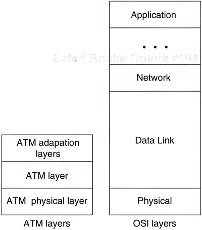
As Figure 5-1 shows, these three layers correspond roughly to Layer 1 and parts of Layer 2 (such as error control and data framing) of the OSI reference model.
The ATM physical layer controls transmission and receipt of bits on the physical medium. It also keeps track of ATM cell boundaries and packages cells into the appropriate type of frame for the physical medium being used. The ATM physical layer is divided into two parts:
Physical medium sublayer
Transmission convergence sublayer
The physical medium sublayer is responsible for sending and receiving a continuous flow of bits with associated timing information to synchronize transmission and reception. Because it includes only physical medium–dependent functions, its specification depends on the physical medium used. Some existing standards that can carry ATM cells are Category 5 copper wiring, SONET (Synchronous Optical Network)/SDH, DS-3/E3, 100-Mbps local fiber (Fiber Distributed Data Interface [FDDI] physical layer), and 155-Mbps local fiber (Fiber Channel physical layer).
The transmission convergence sublayer is responsible for the following:
Cell delineation—. Maintains ATM cell boundaries.
Header error-control sequence generation and verification—. Generates and checks the header error-control code to ensure valid data.
Cell-rate decoupling—. Inserts or suppresses idle (unassigned) ATM cells to adapt the rate of valid ATM cells to the payload capacity of the transmission system.
Transmission-frame adaptation—. Packages ATM cells into frames acceptable to the particular physical layer implementation.
Transmission-frame generation and recovery—. Generates and maintains the appropriate physical layer frame structure.
The ATM layer establishes virtual connections and passes ATM cells through the ATM network. To do this, it uses the information contained in the header of each ATM cell. The ATM layer is responsible for performing the following functions:
Delivers the 48-byte payload on an established ATM connection.
Multiplexes and demultiplexes the cells of different virtual connections. These connections are identified by their virtual channel identifier (VCI) and virtual path identifier (VPI) values.
Performs cell identification to determine cell type and priority.
The ATM layer is a complex layer for network designers more accustomed to other networking fundamentals. This complexity arises from the QoS issues traditionally only seen within telecommunication switches. The complexity is further compounded because of the granularity needed to support traffic with various QoS needs (from stringent to no QoS needed).
QoS is based on performance parameters formerly defined by the ATM Forum. The following parameters may be negotiated during session setup:
Peak-to-peak cell delay variation (peak-to-peak CDV)—. The difference between the best cell transfer delay and the worst cell transfer delay. The worst case is based on a predefined probability-based value.
Maximum cell transmission delay (maxCTD)—. The predefined low probable maximum cell transmission delay.
Cell loss ration (CLR)—. The ration of lost cells to total cells. A CLR can be negotiated for each class of cells (high or low priority) or all cells.
In addition to the negotiable parameters just listed, there are also parameters based on statistical data; these are, therefore, not negotiated:
Cell error ration (CER)—. Ratio of errors to total cells.
Cell misinsertion rate (CMR)—. Rate of misinserted cells. This is the number of cells that were received, but that should have been sent to another ATM device.
Severely errored cell block ratio (SECBR)—. Ratio of severely errored cell blocks to total cell blocks.
The AAL is responsible for segmentation and reassembly of upper-layer data. The AAL must provide a payload of 48 bytes to the ATM layer. In addition to the segmentation and reassembly, the AAL also provides specific services to the upper layers. The ITU-T recommends four service classes: Class A, Class B, Class C, and Class D; these classes are based on characteristics of the requested session:
Class A—. Connection-oriented, constant bit rate, delay-/time-sensitive session
Class B—. Connection-oriented, variable bit rate, delay-/time-sensitive session
Class C—. Connection-oriented, variable bit rate, no delay-/time-sensitive relation required
Class D—. Connectionless-oriented, variable bit rate, no delay-/time-sensitive relation required
To implement the four service types, four AAL layers (protocols) have been specified.
Table 5-1 summarizes the characteristics of each AAL.
Table 5-1. ATM Adapter Layers
| Characteristics | AAL1 | AAL2 | AAL3/4 | AAL5 |
|---|---|---|---|---|
| Requires timing between source and destination | Yes | Yes | No | No |
| Data rate | Constant | Variable | Variable | Variable |
| Connection mode | Connection oriented | Connection oriented | Connection oriented | Connection oriented |
| Traffic types | Voice and circuit emulation | Voice (telephone quality) | Data | Data |
AAL1 is appropriate for transporting telephone traffic and uncompressed video traffic. It requires timing synchronization between the source and destination and, for that reason, depends on a medium that supports clocking, such as SONET. Clock recovery is performed by the receiver using the clock recovery bit in the header.
AAL1 uses bits of the payload to define additional fields. The payload data consists of a synchronous sample (for example, one byte of data generated at a sampling rate of 125 microseconds); the sequence number (SN) field; and sequence number protection (SNP) fields, which provide the receiving AAL1 ordering information to ensure proper reassembly. A three-bit cyclic redundancy check also provides error detection and recovery.
AAL2 is designed to provide services to low–bit-rate, delay-sensitive applications such as telephone-quality voice services. Because the traffic in these types of applications is of variable length, Logical Link Controls (LLCs) were designed to provide virtual point-to-point connections that use the LLC field and length field to assemble the smaller variable-length packets into ATM cells.
AAL3/4 was designed for network service providers and is closely aligned with Switched Multimegabit Data Service (SMDS). AAL3/4 is used to transmit SMDS packets over an ATM network.
AAL3/4 uses field identifiers for the following:
Type—. Identifies whether the cell is the beginning of a message, continuation of a message, or end of a message.
Sequence number—. Identifies the order in which cells should be reassembled.
Multiplexing identifier—. Identifies cells from different traffic sources interleaved on the same virtual circuit connection (VCC), so that the correct cells are reassembled at the destination.
CRC trailer—. Provides error detection and correction.
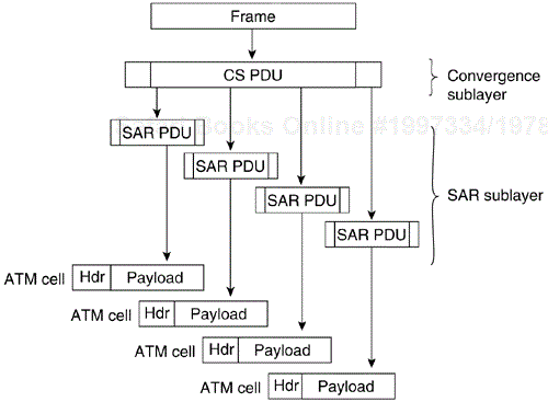
Figure 5-2 shows how the cells are prepared for AAL3/4.
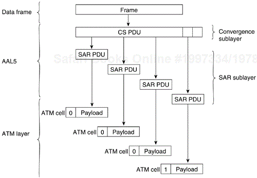
AAL5 prepares a cell for transmission, as shown in Figure 5-3.
First, the convergence sublayer of AAL5 appends a variable-length pad and an eight-byte trailer to a frame. The pad is long enough to ensure that the resulting PDU falls on the 48-byte boundary of the ATM cell. The trailer includes the length of the frame and a 32-bit CRC computed across the entire PDU, which allows AAL5 at the destination to detect bit errors and lost cells, or cells that are out of sequence.
Next, the segmentation and reassembly sections the CS PDU into 48-byte blocks. Then, the ATM layer places each block into the payload field of an ATM cell. For all cells except the last cell, a bit in the PT field is set to zero to indicate that the cell is not the last cell in a series that represents a single frame. For the last cell, the bit in the PT field is set to one. When the cell arrives at its destination, the ATM layer extracts the payload field from the cell; the SAR sublayer reassembles the CS PDU; and the CS uses the CRC and the length field to verify that the frame has been transmitted and reassembled correctly.
AAL5 is the adaptation layer used to transfer most non-SMDS data, such as classical IP over ATM and local-area network (LAN) emulation.
ATM addressing uses the ATM layer for addressing. Unlike an IP node, this addressing requires that the end ATM node know the complete path to the destination. ATM addressing bypasses the overhead associated with in-transit routing decisions; however, ATM devices must, at least within ATM edge switches, provide Layer 3 logical addressing.
Several ATM address formats have been developed. Public ATM networks typically use E.164 numbers, which are also used by narrowband ISDN (N-ISDN) networks.
Figure 5-4 shows the format of private-network ATM addresses. The three formats are Data Country Code (DCC), International Code Designator (ICD), and Network Service Access Point (NSAP)–encapsulated E.164 addresses.
The fields of an ATM address are as follows:
AFI—. One byte of authority and format identifier. The AFI field identifies the type of address. The defined values are 45, 47, and 39 for E.164, ICD, and DCC addresses, respectively.
DFI—. One byte of domain specific part (DSP) format identifier.
ESI—. Six bytes of end-system identifier, which is an IEEE 802 Media Access Control (MAC) address.
The ATM address formats are modeled on ISO NSAP addresses, but they identify Subnetwork Point of Attachment (SNPA) addresses. Incorporating the MAC address into the ATM address makes it easy to map ATM addresses into existing LANs.
The ATM Forum has defined multiple standards for encoding ATM over various types of media. Table 5-2 lists the framing Wtypes and data rates for the various media, including unshielded twisted-pair (UTP) supported by Cisco products.
Table 5-2. ATM Physical Rates
| Media | |||||||
|---|---|---|---|---|---|---|---|
| Framing | Data Rate (Mbps) | Multimode Fiber | Single Mode Fiber | Coaxial Cable | UTP-3 | UTP-5 | STP |
| DS-1 | 1.544 | X | |||||
| E1 | 2.048 | X | |||||
| DS-3 | 45 | X | |||||
| E3 | 34 | X | |||||
| STS-1 | 51 | X | |||||
| SONET STS3c | 155 | X | X | X | X | ||
| SDH STM1 | |||||||
| SONET STS12c | 622 | X | X | ||||
| SDH STM4 | |||||||
| TAXI 4B/ 5B | 100 | X | |||||
| 8B/10B | 155 | X | X | ||||
| Fiber Channel) | |||||||
There are two standards for running ATM over copper cable: Category 3 and Category 5. Category 5 supports 155 Mbps with NRZI encoding; Category 3 supports 51 Mbps with CAP-16 encoding. CAP-16 is more difficult to implement; so, although it may be cheaper to wire with UTP-3 cable, workstation cards designed for CAP-16–based UTP-3 may be more expensive and will offer less bandSwidth.
ATM's support of fiber and copper cable will ease future migrations by organizations with large investments in fiber and copper.
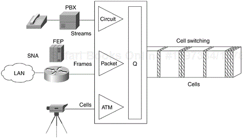
ATM has emerged as one of the technologies for integrating services as well as for providing WAN services to connect LANs. ATM is also a LAN; however, its LAN usage has not been as popular because of Ethernet's continued growth in the 100-Megabit and Gigabit arena. ATM supports various traffic types in separate or mixed streams, delay-sensitive traffic, and nondelay-sensitive traffic, as shown in Figure 5-5.
ATM supports various speeds from 1.54 Mbps to 622 Mbps. ATM has been adopted by the industry's equipment vendors, from LAN to private branch exchange (PBX) to international carriers. With ATM, Cisco's ATM switches, and ATM edge routers, network designers can integrate services, provide LAN-to-WAN connectivity, and cost-effectively support emerging applications for their enterprises.
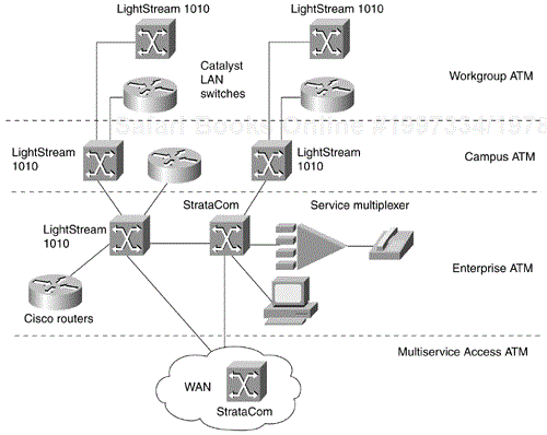
The trend in networking is to give network designers greater flexibility to solve multiple networking problems without creating multiple networks or writing off existing data-communications investments. Routers can provide a reliable, secure network and act as a barrier against inadvertent broadcast storms in the local networks. Switches, which can be divided into two main categories—LAN switches and WAN switches—can be deployed at the workgroup, campus backbone, or WAN level, as shown in Figure 5-6.
Underlying and integrating all Cisco products is the Cisco IOS software. The Cisco IOS software enables disparate groups, diverse devices, and multiple protocols all to be integrated into a highly reliable and scalable network.
Even though all ATM switches perform cell relay, ATM switches differ markedly in the following ways:
Variety of interfaces and services that are supported
Redundancy
Depth of ATM networking software
Sophistication of traffic-management mechanism
Just as there are routers and LAN switches available at various price/performance points with different levels of functionality, ATM switches also come in various configurations to support various ATM integration into workgroups, campuses, and the enterprise.
Workgroup ATM switches are often characterized as having Ethernet switch ports and an ATM uplink to connect to a campus ATM switch; however, due to the popularity of switched 100-Mb Ethernet, campus and enterprise ATM switches are also supporting Ethernet ports. An example of a workgroup ATM switch is the Cisco Catalyst 5000 family of switches.
The Catalyst 5500 switch provides high-performance switching in workgroup and campus environments. The Catalyst 5500 LAN has a 13-slot chassis. Slot 1 is reserved for the supervisor engine module, which provides switching, local and remote management, and dual Fast Ethernet uplinks. Slot 2 is available for a second redundant supervisor engine or any of the other supported modules. Slots 3–12 support Ethernet, Fast Ethernet, Gigabit Ethernet, Fiber Distributed Data Interface (FDDI), Copper Distributed Data Interface (CDDI), and ATM modules. Slot 13 can be populated only with a LightStream 1010 ATM Switch Processor (ASP). If an ASP is present in slot 13, slots 9–12 support any of the standard LightStream 1010 ATM switch port adapter modules (PAMs).
The Catalyst 5500 has a 10-Gbps media-independent switch fabric and a 40-Gbps cell-switch fabric. The backplane provides the connection between power supplies, supervisor engine, interface modules, and backbone module. The 3.6-Gbps media-independent fabric supports Ethernet, Fast Ethernet, FDDI/CDDI, ATM LAN Emulation, and RSM modules. The 5-Gbps cell-based fabric supports a LightStream 1010 ASP module and ATM PAMs.
Campus ATM switches are generally used for small-scale ATM backbones (for instance, to link ATM routers or LAN switches). This use of ATM switches can alleviate current backbone congestion while supporting the deployment of virtual LANs (VLANs). Campus switches need to support a wide variety of both local backbone and WAN types, but also need to be price/performance optimized for the local backbone function. In this class of switches, ATM routing capabilities that allow multiple switches to be tied together are very important. Congestion-control mechanisms for optimizing backbone performance are also important.
Cisco's expansion of campus ATM switches includes the Catalyst 8500 family of products.
The Catalyst 8540 supports 40 Gbps of nonblocking switch-fabric performance. The first three slots are reserved for the processor modules. Two modules are required, and the third redundant module can be used in the third slot. The remaining 10 ports support Ethernet, Fast Ethernet, Gigabit Ethernet, and OC3c (155 Mbps) and OC12c (622 Mbps) ATM.
Enterprise ATM switches are sophisticated multiservice, multimedium, and multiprotocol devices designed to form the core backbones of large enterprise networks. They are intended to complement, and in some cases replace, the role of today's high-end multiprotocol routers. Enterprise ATM switches are used to interconnect campus ATM switches. Enterprise class switches, however, can act not only as ATM backbones, but can also serve as the single point of integration for all the disparate services and technology found in enterprise backbones today. By integrating all these services onto a common platform and a common ATM transport infrastructure, network designers can gain greater manageability and eliminate the need for multiple overlay networks.
Cisco's LightStream 1010 is an enterprise switch that can support the enterprise backbone or provide edge ATM services to the enterprise. The LightStream 1010 ATM switch comes with a five-slot modular chassis that supports dual fault-tolerant load-sharing power supplies. The ATM switch processor is located in the central slot, and the switch fabric supports speed up to 5 Gbps. The LightStream 1010 family of ATM switches is an example of a campus ATM switch with support for multiple ATM segments. The LightStream 1010 will support up to 32 switched OC-3 ATM ports in a standard 19-inch (48-centimeter) rack. For more information on deploying workgroup and campus ATM switches in your network, see Chapter 12, "Designing Switched LAN Networks."
Cisco's BPX 8600 is a powerful broadband ATM edge switch designed to meet the demanding, high-traffic needs of a large private enterprise or public service provider. The switch has 15 slots, two of which support the redundant broadband control cards made up of the switching fabric and control system. An additional slot is used by the status monitor. The remaining 12 cards can be used to support BPX, IGX, MGX, or ATM UNI and NNI interfaces. The switch's performance is optimized through the use of both input and output switch buffers.
IP networking requires high-performance routers, as well as ATM switching services.
The Cisco 7500 router incorporates distributed switching functions that enable network designers to provide the high-performance routing necessary to support networks using ATM, multilayer LAN switching, emulated LAN (ELAN), and virtual LAN (VLAN) technologies.
The Cisco 7500 family of routers offers broad support for high-speed ATM and WAN interfaces. The high port densities supported by the Cisco 7500 series easily handle the large number of interfaces required for remote-site connectivity. Network designers can deploy the Cisco 7500 series in the WAN environment to access multiple types of carrier-service offerings, including ATM backbones. The router provides 2.1 Gbps of throughput.
The Cisco 7500 also provides the redundant power supplies expected of high-end routers and a redundant Route Switch Processor (RSP), as well as load sharing for IP (other protocols are planned) if the redundant RSP is present. The Cisco 7500 has proved to be the enterprise router of choice; and with its ATM support, it can act as a campus or enterprise edge ATM router.
Beyond private networks, ATM platforms are also widely deployed by service providers, both as customer premises'equipment and within public networks. Such equipment supports multiple WAN services, including Frame Relay switching, IP-based services, ATM NNI interconnect, and public ATM services exploiting a common ATM infrastructure. These high-end enterprise ATM switches, often referred to as carrier class, will often be used in these public-network applications because of their emphasis on high availability and redundancy, their support of multiple interfaces, and their capability to integrate voice and data. The Cisco BPX 8600, discussed earlier, is an example of a carrier class ATM switch. As the telecommunications industry further expands, especially in Europe, the demand for carrier class switches will also expand.
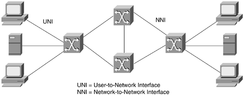
ATM is based on the concept of two endpoint devices communicating by means of intermediate switches. As Figure 5-7 shows, an ATM network is made up of a series of switches and endpoint devices. The endpoint devices can be ATM-attached end stations, ATM-attached servers, or ATM-attached routers.
As Figure 5-7 shows, an ATM network has two types of interfaces:
The UNI connection is made up of an endpoint device, and a private or public ATM switch. Early ATM developers were mostly concerned with the UNI interface to bring products to market.
The NNI is the connection between two ATM switches. The UNI and NNI connections can be carried by different physical connections.
In addition to the UNI and NNI protocols, the ATM Forum has defined protocols to support LAN Emulation (LANE). LANE is a technology network that designers use to network LANs, such as Ethernet and Token Ring, with ATM-attached devices. The need to connect Ethernet and Token Ring networks to ATM networks has created the largest market for ATM edge switches. (Early ATM designers assumed that Ethernet and Token Ring would be phased out as soon as ATM gained popularity, but switched 100-Mb and Gigabit Ethernet have ensured Ethernet's continued growth.)
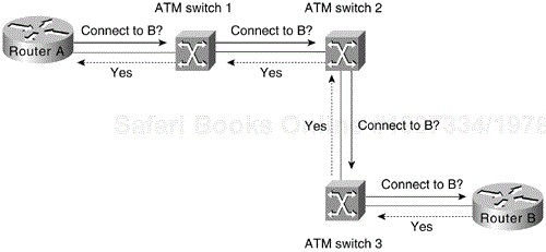
In an ATM network, a connection must be established between two endpoints before any data transfer can occur. This connection is accomplished through a signaling protocol, as shown in Figure 5-8.
As Figure 5-8 shows, for Router A to connect to Router B, the following must occur:
Router A sends a signaling request packet to its directly connected ATM switch (ATM switch 1).
This request contains the ATM address of Router B, as well as any QoS parameters described later required for the connection.
ATM switch 1 reassembles the signaling packet from Router A, and then examines it.
If ATM switch 1 has an entry for Router B's ATM address in its switch table, and it can accommodate the QoS requested for the connection, it sets up the virtual connection and forwards the request to the next switch (ATM switch 2) along the path.
Every switch along the path to Router B reassembles and examines the signaling packet, and then forwards it to the next switch if the QoS parameters can be supported. Each switch also sets up the virtual connection as the signaling packet is forwarded.
If any switch along the path cannot accommodate the requested QoS parameters, the request is rejected and a rejection message is sent back to Router A with a possible lower QoS available.
When the signaling packet arrives at Router B, Router B reassembles it and evaluates the packet. If Router B can support the requested QoS, it responds with an accept message. As the accept message is propagated back to Router A, the switches set up a virtual circuit.
Note
A virtual channel is equivalent to a virtual circuit—that is, both terms describe a logical connection between the two ends of a communications connection. A virtual path is a logical grouping of virtual circuits that allows an ATM switch to perform operations on groups of virtual circuits.
Note
ATM cells consist of five bytes of header information and 48 bytes of payload data. The VPI and VCI fields in the ATM header are used to route cells through ATM networks. The VPI and VCI fields of the cell header identify the next network segment that a cell needs to transmit on its way to its final destination.
The ATM Forum has defined a standard for LANE. LANE is a technology that network designers can deploy to network existing Ethernet and Token Ring LANs with ATM networks. LANE provides MAC encapsulation (OSI Layer 2) to support the highest number of existing OSI Layer 3 protocols. The end result is that all devices attached to an emulated LAN (ELAN) appear to be on one bridged segment. In this way, AppleTalk, IPX, IP, and other protocols will have similar performance characteristics as in a traditional bridged environment using the same media; however, network communications between ELANs still have to communicate through a Layer 3 router. Because communicating through the Layer 3 router adds unnecessary latency in an ATM network that would not normally require Layer 3 services except to support the existing Ethernet and Token Ring LANs, the ATM Forum defined Multiprotocol over ATM.
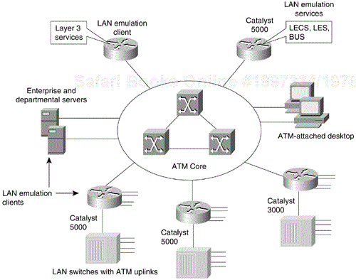
Figure 5-9 shows an example of an ATM LANE network that uses routers for inter-ELAN communications.
Using Multiprotocol over ATM, the ATM stations realize that inter-ELAN communication is taking place and build a direct "shortcut" to the receiving station, effectively bypassing the latency that occurs in the topology shown in Figure 5-9.
LANE components include the following:
LAN Emulation Client (LEC)—. ATM systems that support both the LAN, such as Ethernet or Token Ring, and ATM LANE—for example, the Catalyst family of switches and Cisco 7500, 7000, 4500, and 4000 series routers that support ATM attachments. The LEC emulates an interface to a legacy LAN to the higher-level protocols, as well as performs data forwarding, address resolution, and registration of MAC addresses with the LAN Emulation server (LES). The LEC communicates with other LECs via ATM virtual channel connections (VCCs).
LAN Emulation Configuration Server (LECS)—. The LECS maintains a database of ELANs and the ATM addresses of the LESs that control the ELANs. An LECS accepts queries from LECs and responds with the ATM address of the LES that serves the appropriate ELAN.
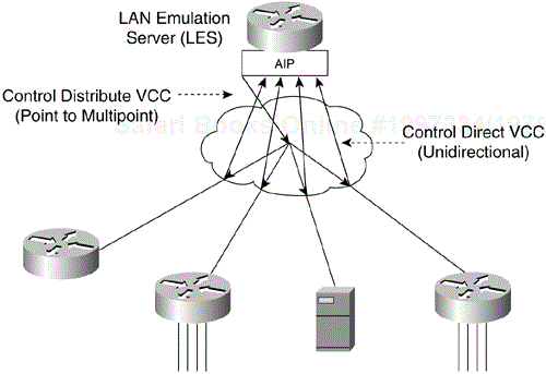
LAN Emulation Server (LES)—. The LES provides a central control point for all LECs. LECs maintain a Control Direct VCC to the LES to forward registration and control information. The LES maintains a point-to-multipoint VCC, known as the Control Distribute VCC, to all LECs. The Control Distribute VCC is used only to forward control information. As new LECs join the ATM ELAN, each LEC is added as a leaf to the Control Distribute tree.
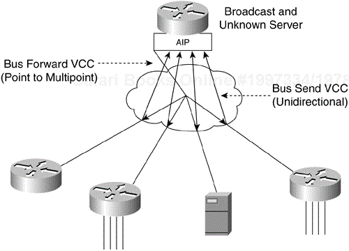
Broadcast and Unknown Server (BUS)—. The BUS acts as a central point for distributing broadcasts and multicasts. ATM is a point-to-point technology without broadcast support. LANE solves this problem by centralizing the broadcast support in the BUS. Each LEC must set up a Multicast Send VCC to the BUS. The BUS then adds the LEC as a leaf to its point-to-multipoint VCC (known as the Multicast Forward VCC).
The BUS also acts as a multicast server. LANE is defined on ATM adaptation layer 5 (AAL5), which specifies a simple trailer to be appended to a frame before it is broken into ATM cells. The problem is that there is no way to differentiate between ATM cells from different senders when multiplexed on a virtual channel. It is assumed that cells received will be in sequence, and when the End of Message (EOM) cell arrives, you should just have to reassemble all the cells that have already arrived.
The BUS takes the sequence of cells on each Multicast Send VCC and reassembles them into frames. When a full frame is received, it is queued for sending to all the LECs on the Multicast Forward VCC. This guarantees that all the cells from a particular data frame will be sent in order and not interleaved with cells from any other data frames on the point-to-multipoint VCC.
Note that because LANE is defined at OSI Layer 2, the LECS is the only security checkpoint available. After it has been told where to find the LES and it has successfully joined the ELAN, the LEC is free to send any traffic (whether malicious or not) into the bridged ELAN. The only place for any OSI Layer 3 security filters is in the router that routes this ELAN to other ELANs, and this security is bypassed once Multiprotocol over ATM has completed a "shortcut" to bypass the router. Therefore, the larger the ELAN, the greater the exposure to security violations.
An ELAN provides Layer 2 communication between all users on an ELAN. One or more ELANs can run on the same ATM network. However, each ELAN is independent of the others and users on separate ELANs cannot communicate directly. As mentioned, routers or MPOA is required for inter-ELAN communication.
Because an ELAN provides Layer 2 communication, it can be equated to a broadcast domain. In addition, IP subnets and IPX networks that are defined on Layer 3–capable devices such as routers frequently map into broadcast domains (barring secondary addressing). This makes it possible to assign an IP subnetwork or an IP network to an ELAN.
An ELAN is controlled by a single LES/BUS pair, and the mapping of an ELAN to its LES ATM address is defined in the LEC's database. ELANs consist of multiple LECs and can be Ethernet or Token Ring, but not both at the same time.
For ELAN to operate properly, the LECs on that ELAN need to be operational. Each LEC goes through a boot-up sequence, as described in the following sections.
In a typical LANE operation, the LEC must first find the LECS to discover which ELAN it should join. Specifically, the LEC is looking for the ATM address of the LECS that serves the desired ELAN.
To resolve the ATM address of the LECS, the LEC does the following:
Queries the ATM switch via Interim Local Management Interface (ILMI). The switch has a MIB variable set up with the ATM address of the LECS. The LEC can then use UNI signaling to contact the LECS.
Looks for a fixed ATM address specified by the ATM Forum as the LECS ATM address.
Accesses permanent virtual circuit (PVC) 0/17, a well-known PVC.
The LEC creates a signaling packet with the ATM address of the LECS. It signals a Configure Direct VCC and then issues an LE_CONFIGURE_REQUEST on that VCC. The information in this request is compared with the data in the LECS database. The source ATM address is most commonly used to place an LEC into a specific ELAN. If a matching entry is found, a successful LE_CONFIGURE_RESPONSE is returned with the ATM address of the LES that serves the desired ELAN.
You can configure the LECS database in any of the following three ways:
Configure ELAN names at the LEC—. In this configuration, all the LECs are configured with an ELAN name that they can embed in their Configure_Requests. This is the most basic form of the LECS database, and it needs only to contain the list of ELANs and their corresponding LES ATM addresses. In this configuration, all LECs that specifically request to join a given ELAN are returned the ATM address of the corresponding LES. An LEC that does not know which ELAN to join can be assigned to a default ELAN if one is configured in the LECS database.
The following is an example of LEC-to-ELAN mapping at the LEC:
lane database test-1
name finance server-atm-address 47.0091.8100.0000.0800.200c.1001.
  0800.200c.1001.01
name marketing server-atm-address 47.0091.8100.0000.0800.200c.1001.
  0800.200c.1001.02
default-name finance
Configure LEC to ELAN assignment in the LECS database—. In this configuration, all the information is centralized in the LECS database. The LECs do not need intelligence, and they can just query the LECS to determine which ELAN they should join. Although this is a more time-intensive configuration, it provides tighter control over all the ELANs. Consequently, it can be used to tighten security.
With this method, the LECs are identified by their ATM addresses or MAC addresses. Because wildcarding of ATM address prefixes is also supported, it is useful to make such relationships as, "Assign any LEC joining with a prefix of A to ELAN X." The following is an example of LEC-to-ELAN mapping in the LECS database:
lane database test-2
name finance server-atm-address 47.0091.8100.0000.0800.200c.1001.
  0800.200c.1001.01
name marketing server-atm-address 47.0091.8100.0000.0800.200c.1001.
  0800.200c.1001.02
default-name finance
client-atm-address  47.0091.8100.0000.08  name finance
client-atm-address  47.0091.8100.0000.09  name marketing
mac-address 00c0.0000.0100 name finance
mac-address 00c0.1111.2222 name marketing
Hybrid combination—. You can configure a combination of the preceding two methods.
After the LEC has discovered the ATM address of the desired LES, it drops the connection to the LECS, creates a signaling packet with the ATM address of the LES, and signals a Control Direct VCC. Upon successful VCC setup, the LES sends an LE_JOIN_REQUEST. This request contains the LEC ATM address, as well as a MAC address that the LEC wants to register with the ELAN. This information is maintained so that no two LECs can register the same MAC or ATM addresses.
Upon receipt of the LE_JOIN_REQUEST, the LES checks with the LECS via its own open connection with the LECS, and verifies the request, thus confirming the client's membership. Upon successful verification, the LES adds the LEC as a leaf of its point-to-multipoint Control Distribute VCC. Finally, the LES issues the LEC a successful LE_JOIN_RESPONSE that contains a LANE client ID (LECID), which is an identifier unique to the new client. This ID is used by the LEC to filter its own broadcasts from the BUS. Figure 5-10 shows examples of LES connections.
After the LEC has successfully joined the LES, its first task is to resolve the ATM address of the BUS and join the broadcast group. The LEC creates an LE_ARP_REQUEST packet with the MAC address 0xFFFFFFFF. This special LE_ARP packet is sent on the Control Direct VCC to the LES. The LES recognizes that the LEC is looking for the BUS, responds with the ATM address of the BUS, and forwards that response on the Control Distribute VCC.
When the LEC has the ATM address of the BUS, its next action is to create a signaling packet with that address and signal a Multicast Send VCC. Upon receipt of the signaling request, the BUS adds the LEC as a leaf on its point-to-multipoint Multicast Forward VCC. At this time, the LEC has become a member of the ELAN. Figure 5-11 shows examples of BUS connections.
The real value of LANE is the ATM forwarding path that it provides for unicast traffic between LECs. When an LEC has a data packet to send to an unknown destination, it issues an LE_ARP_REQUEST to the LES on the Control Direct VCC. The LES forwards the request on the Control Distribute VCC, so all LEC stations hear it. In parallel, the unicast data packets are sent to the BUS, to be forwarded to all endpoints. This flooding is not the optimal path for unicast traffic, and this transmission path is limited to 10 packets per second (per the LANE standard). Unicast packets continue using the BUS until the LE_ARP_REQUEST has been resolved.
If bridging or switching devices with LEC software participate in the ELAN, they translate and forward the ARP on their LAN interfaces. One of the LECs should issue an LE_ARP_RESPONSE and send it to the LES, which forwards it to the Control Distribute VCC so that all LECs can learn the new MAC-to-ATM address binding. The 10 packet per second flooding is then no longer needed.
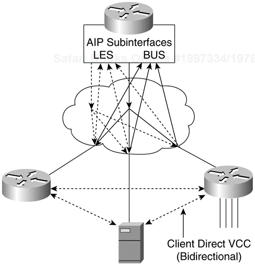
When the requesting LEC receives the LE_ARP_RESPONSE, it has the ATM address of the LEC that represents the MAC address being sought. The LEC should now signal the other LEC directly and set up a Data Direct VCC that will be used for unicast data between the LECs.
While waiting for LE_ARP resolution, the LEC forwards unicasts to the BUS. With LE_ARP resolution, a new optimal path becomes available. If the LEC switches immediately to the new path, it runs the risk of packets arriving out of order. To guard against this situation, the LANE standard provides a flush packet.
When the Data Direct VCC becomes available, the LEC generates a flush packet and sends it to the BUS. When the LEC receives its own flush packet on the Multicast Forward VCC, it knows that all previously sent unicasts must have already been forwarded. It is now safe to begin using the Data Direct VCC. Figure 5-12 shows an example of a fully connected ELAN.
As Table 5-3 indicates, the LANE functionality (the LECS, LEC, LES, and BUS) can be implemented in different Cisco devices.
Table 5-3. Cisco LANE Implementation
| Cisco Product | Available LANE Components | Required Software Release |
|---|---|---|
| Family of Catalyst 5000 switches | LECS, LES, BUS, LEC | ATM Module Software Version 2.0 or later |
| Family of Catalyst 3000 switches | LECS, LES, BUS, LEC | ATM Module Software Version 2.1 or later |
| Family of Cisco 7000 routers | LECS, LES, BUS, LEC | Cisco IOS Software Release 11.0 or later |
| Family of Cisco 7500 routers | LECS, LES, BUS, LEC | Cisco IOS Software Release 11.1 or later |
| Family of Cisco 4500 and 4000 routers | LECS, LES, BUS, LEC | Cisco IOS Software Release 11.1 or later |
These functions will be defined on ATM physical interfaces and subinterfaces. A subinterface can be defined as a logical interface, and is a part of a physical interface such as an Optical Carrier 3 (OC-3) fiber. ATM interfaces on the Cisco routers and the ATM module on the Catalyst 5000 switch can be logically divided into up to 255 logical subinterfaces.
This section examines the implementation of ATM LANE networks and covers the following topics:
LANE Design Considerations
LANE Redundancy
The following are some general LANE design considerations:
The ATM Interface Processor (AIP) provides an interface to ATM switching fabrics for transmitting and receiving data. The data rate is determined by the physical layer interface module (PLIM).
One active LECS supports all ELANs.
In each ELAN, there is one LES/BUS pair and some number of LECs.
The LES and BUS functionality must be defined on the same subinterface and cannot be separated.
There can be only one LES/BUS pair per ELAN.
The current LANE Phase 1 standard does not provide for any LES/BUS redundancy.
The LECS and LES/BUS can be different routers, bridges, or workstations.
VCCs can be either switched virtual circuits (SVCs) or permanent virtual circuits (PVCs), although PVC design configuration and complexity might make anything more than a very small network prohibitively unmanageable and complex.
If an LEC on a router subinterface is assigned an IP, IPX, or AppleTalk address, that protocol is routable over that LEC. If there are multiple LECs on a router and they are assigned protocol addresses, routing will occur between the ELANs. For routing between ELANs to function correctly, an ELAN should be in only one subnet for a particular protocol.
Network designers can deploy PNNI as a Layer 2 routing protocol for bandwidth management, traffic distribution, and path redundancy for LANE networks. PNNI is an ATM routing protocol used for routing call setups, and is implemented in the ATM switches. Most LANE networks consist of multiple ATM switches and typically employ the PNNI protocol.
Note
Although PNNI is an advanced routing protocol and supports QoS-based routing, this particular aspect of PNNI is not discussed in this chapter because most LANE networks are based on the best-effort traffic category.
Some PNNI-related features that can be useful in scaling LANE networks are the following:
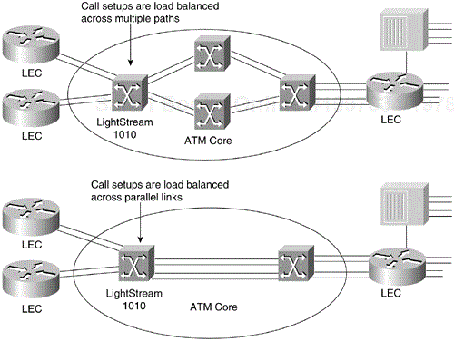
Support of load-balance call setup requests across multiple paths between two end stations
Support of load-balance call setups across multiple parallel links
Support for link and path redundancy with fast convergence
Excellent call setup performance across multiple hops using the background routing feature
Figure 5-13 shows how the Light Stream 1010 switch supports load balancing.
As Figure 5-13 shows, load balancing of calls is enabled by default on the LightStream 1010 switch. Background routing, however, is not enabled by default. Background routing can be thought of as routing of call setups using a path from a precomputed route database. The background routing process computes a list of all possible paths, to all destinations, and across all the service categories (for example, constant bit rate [CBR], virtual bit rate-real time [VBR-RT], virtual bit rate and non-real time [VBR-NRT], and available bit rate-unspecified bit rate [ABR-UBR]).
When a call is placed from Point A to Point B, PNNI picks a cached routed from the background route table instead of computing a route on demand. This eases the CPU load and provides a faster rate of processing the call setups.
Background routing can be useful in networks that have a stable topology with respect to QoS. It is, however, not very effective in networks that have rapidly changing topologies (for example, Internet service provider [ISP] networks or carrier networks). Campus LANE networks can use this feature effectively because all the SVCs in the network belong to the UBR or ABR category. To enable this feature, use the following command:
  atm router pnni
    node 1 level 56
    bg-routes
The current implementation of PNNI on the LightStream 1010 switch is fully ATM Forum-PNNI Version 1-compliant. The LightStream default PNNI image license supports a single level of hierarchy, in which multiple peer groups can be interconnected by IISP or by other switches that support full PNNI hierarchy; extra PNNI image licenses will support multiple levels of routing hierarchy.
The PNNI protocols have been designed to scale across all sizes of ATM networks, from small campus networks of a handful of switches, to the possible global ATM Internet of millions of switches. This level of scalability is greater than that of any existing routing protocol, and requires very significant complexity in the PNNI protocol.
Specifically, such scalability mandates the support of multiple levels of routing hierarchy, based on the use of prefixes of the 20-byte ATM address space. The lowest level of the PNNI routing hierarchy consists of a single peer group within which all switches flood all reachability and QoS metrics to one another. This is analogous, for instance, to a single area in the OSPF protocol.
Subsequently, multiple peer groups at one level of the hierarchy are aggregated into higher-level peer groups, within which each lower-level peer group is represented by a single peer group leader, and so on iteratively up the PNNI hierarchy. Each level of the hierarchy is identified by a prefix of the ATM address space, implying that PNNI could theoretically contain more than 100 levels of routing hierarchy. However, a handful of levels would be adequate for most networks. The price to be paid for such scalability is the need for highly complex mechanisms for supporting and bringing up the multiple levels of hierarchy, and for electing the peer-group leaders within each peer group at each level.
Spanning-Tree Protocol is a Layer 2 protocol supported by switches and bridges to prevent temporary loops in networks with redundant links. Because an LEC bridges Ethernet/Token Ring traffic over an ATM backbone, the spanning-tree bridge protocol data units (BPDUs) are transmitted over the entire ELAN. The ATM network appears as a shared Ethernet/Token Ring network to the spanning-tree process at the edge of the Layer 2 switches.
The spanning-tree topology of a LANE-based network is substantially simpler than a pure frame-switched network that employs the Spanning-Tree Protocol. It follows that spanning-tree convergence times, which can be a major issue in large frame-switched networks, can be less of an issue in LANE networks. Note that spanning tree must reconverge if there are failures at the edge devices or inside the ATM network. If there is a need to tune the convergence time to a lower or higher value, the forward delay parameter can be used.
Although LANE enables network designers to connect their legacy LANs to an ATM network, LANE Version 1.0 does not define mechanisms for building redundancy and fault tolerance into the LANE services. Consequently, this makes the LANE services a single point of failure. Moreover, router redundancy and path/link redundancy are also issues that the network designer needs to consider.
Network designers can use the following techniques to build fault-tolerant and resilient LANE networks:
Simple Server Replication Protocol (SSRP) for LANE provides redundancy that works with Cisco and any third-party LECs.
Hot Standby Router Protocol (HSRP) over LANE provides redundancy for the default router configured at IP end stations.
Redundant modules supported by Cisco ATM switches.
Spanning-Tree Protocol on the Ethernet-ATM switches.
The following subsections examine these various mechanisms and highlight design rules and issues to consider while implementing redundant LANE networks. The discussion begins by examining SSRP, which was developed to provide redundant LANE services.
Although many vendors implemented redundant LANE services early on, the services violated the LANE 1.0 specification and therefore were not interoperable with other third-party implementations. SSRP supports the LANE 1.0 specification, however, and is interoperable with third-party LEC implementations, which is important when implementing an interoperable ATM network.
The SSRP discussion is followed by a description of HSRP over LANE, which provides a mechanism for building router redundancy. Following this is an examination of the Spanning-Tree Protocol and other product-specific features that can be used to build link and path redundancy into edge devices.
A major concern with LANE 1.0 networks is that only one set of LANE service components can be accessed by an LEC at any given time. This results in the following limitations:
Only a single LECS supports all ELANs.
There can be only one LES/BUS pair per ELAN.
A failure in any of these service components has the following impact on network operation:
LECS failure—. A failed LECS impacts all the ELANs under its control because it provides access control for all its ELANs. Although the existing ELANs would continue to work normally (assuming only Cisco LECs), no new LEC can join any ELAN under the control of that LECS. Also, any LEC that needs to rejoin its ELAN or change its membership to another ELAN cannot because the LES cannot verify any LEC trying to join an ELAN.
LES/BUS failure—. The LES/BUS pair is needed to maintain an operational ELAN. The LES provides the LE_ARP service for ATM-MAC address mappings, and the BUS provides broadcast and unknown services for a given ELAN. Therefore, a failure of either the LES or the BUS immediately affects normal communication on the ELAN. However, a LES/BUS failure impacts only the ELAN served by that pair.
It is clear that these issues can be limiting to networks in which resiliency and robustness are required; therefore, these issues might even be deciding factors as to whether to implement LANE-based ATM networks. In addition, other design considerations can have implications on the overall robustness of the LANE environment (the placement of the LANE service components within an ATM network, for example).
Increasing the resiliency of a LANE-based network essentially includes delivering increased robustness in the LANE service components such as the LECS, LES, and BUS. Such robustness is provided by SSRP through a primary-secondary combination of the LANE services. For LECS redundancy, one primary LECS is backed up by multiple secondary LECSs. LES/BUS redundancy is also handled in a similar fashion, where one primary LES/BUS pair is backed up by multiple secondaries. Note that the LES/BUS functions are always co-located in a Cisco implementation and the pair is handled as one unit with respect to redundancy.
In the LANE 1.0 specification, the first step for an LEC during initialization is to connect with the LECS to obtain the LES ATM address for the ELAN it wants to join. For the LEC to connect to the LECS, multiple mechanisms are defined. First, the LEC should query the ATM switch it is attached to for the LECS address. This address discovery process is done using the ILMI protocol on VPI, VCI - 0, 16.
The following is an example of the configuration command to add an LECS address to a LightStream 1010 switch:
atm lecs-address <LECS NSAP address> <index>
With SSRP, multiple LECS addresses are configured into the ATM switches. An LEC, which requests the LECS address from the ATM switch, gets the entire table of LECS addresses in response. The LEC first attempts to connect to the highest-ranking LECS address. If this fails, it tries the next one in the list and so on until it connects to the LECS.
Whereas the LEC always tries to connect to the highest-ranking LECS available, SSRP ensures that there is only a single primary that responds to the Configure Request queries coming from the LEC. The establishment of a primary LECS and the placement of the others in backup go to the heart of SSRP. The following describes the way SSRP establishes a primary LECS. Upon initialization, an LECS obtains the LECS address table from the switch and then tries to connect to all the LECSs below itself in rank. The rank is derived from the index entry in the LECS address table.
If an LECS has a connection (VCC) from an LECS whose rank is higher than its own, it is in backup mode. The highest-ranking LECS does not have any other LECS that connects to it from above and assumes the role of the primary LECS.
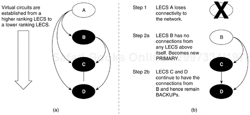
Figure 5-14 shows the procedure of a backup taking over in the case of a failed primary LECS. The LANE network shown in Figure 5-14 has four LECS entities (LECS A, B, C, and D). All the ATM switches in the network are configured with the same LECS address table. After startup, LECS A obtains the LECS address table from the ATM switch it is attached to and finds that it has three LECSs below itself, and therefore tries to connect to LECS B, C, and D. LECS B connects to LECS C and LECS D, and LECS C connects to LECS D. There is a downward establishment of VCCs. Because LECS A does not have any VCCs from above, it becomes the primary LECS.
During normal network operation, LECS A responds to all configure requests, and the backup LECSs (LECS B, C, and D) do not respond to any queries. If for some reason the primary LECS (LECS A) fails because of such conditions as a box failure, LECS B loses its VCC from LECS A, as do the other LECS.
At this point, LECS B does not have any VCCs from above and therefore is now the highest-ranking available LECS in the network. LECS B now becomes the primary LECS. LECS C and LECS D still have connections from higher-ranking LECSs, and therefore continue to operate in backup mode, as shown in Step 2b of Figure 5-14.
The LES/BUS redundancy portion of SSRP supports the configuration of multiple LES/BUS pairs that work in a primary-secondary fashion. However, the mechanisms used here are different from those used for the LECS redundancy described in the preceding section.
Multiple LES/BUS pairs for a given ELAN are first configured into the LECS database. Within this database, each LES/BUS pair is assigned a priority. After initialization, each LES/BUS opens a VCC with the primary LECS using the LECS address discovery mechanism. The LES/BUS pair with the highest priority that has an open VCC to the LECS is assigned as the primary LES/BUS by the primary LECS.
There are no theoretical limits on the number of LECSs that can be configured using SSRP; however, a recommended number is two (one primary and one backup) or three LECSs (one primary and two backups). Any more redundancy should be implemented only after very careful consideration because it will add significant complexity to the network. This added complexity might result in a substantial increase in management time to troubleshoot such networks.
To support the LECS redundancy scheme, you must adhere to the following configuration rules. Failure to do so will result in improper operation of SSRP and a malfunctioning network.
Each LECS must maintain the same database of ELANs. Therefore, you must maintain the same ELAN database across all the LECSs.
You must configure the LECS addresses in the LECS address table in the same order on each ATM switch in the network.
When using SSRP with the Well Known Address, do not place two LECSs on the same ATM switch. If you place two LECs on the same ATM switch, only one LECS can register the Well Known Address with the ATM switch (through ILMI) and this can cause problems during initialization.
SSRP can be used with independent third-party LECs if the third-party LECs use ILMI for LECS address discovery and can appropriately handle multiple LECS addresses returned by the ATM switch. The LEC should step through connecting to the list of LECS addresses returned by the ATM switch, for example. The first LECS that responds to the configuration request is the master LECS.
SSRP also works with LECS Well Known Address (47.0079….) defined in the LANE 1.0 specification. The Cisco LECS can listen on multiple ATM addresses at the same time. Therefore, it can listen on the Well Known Address and the autoconfigured ATM address, which can be displayed using the show lane default command.
When the LECS is enabled to listen on the Well Known Address, it registers the Well Known Address with the ATM switch so that the ATM switches can advertise routes to the Well Known Address and route any call setup requests to the correct place.
Under SSRP, there are multiple LECSs in the network. If each LECS registers the Well Known Address to the ATM switches that it is connected to, call setups are routed to different places in the network. Consequently, under SSRP you must configure an autoconfigured address so that the negotiation of the master first takes place, and then the master registers the Well Known Address with the ATM switch. If the master fails, the Well Known Address moves with the master LECS. The PNNI code on the LightStream 1010 switch takes care of advertising the new route to the Well Known Address when there is a change of LECS mastership. Therefore, third-party LECs that use only the Well Known Address can also interpolate with SSRP. SSRP is the only redundancy scheme that can be used with almost any LEC in the industry.
To implement SSRP with the Well Known Address, follow these steps:
Configure the LECS to listen on the autoconfigured address (or on a separate ATM address that you have predetermined). This autoconfigured (or other) address should be programmed into the ATM switches for the LECS address discovery mechanism.
Configure each LECS to listen on the Well Known Address using the lane config fixed-config-atm-address command. After the master LECS is determined using the LECS redundancy procedure, the master registers the Well Known Address to the ATM switch.
Note
SSRP with the Well Known Address does not work properly under certain circumstances (during failure) if two LECS are attached to the same ATM switch, because of the possibility of duplicate address registration on the same switch (which ILMI does not allow). Make sure each LECS is on a separate ATM switch.
In the event of network partitions in which two separate ATM clouds are formed due to an interconnecting link or switch failure, each cloud has its own set of LANE services if SSRP is configured to handle network partitions.
When configuring SSRP, use the following guidelines to accommodate the possibility of network partition:
Configure each partition with its own LANE services that can become active during a network partition. If you are connecting two sites or campuses across a MAN and you want the same ELANs at both locations, for example, configure each campus/site with its own LANE services.
Routing behavior should be carefully examined during a network partition in the case where an ELAN maps to a Layer 3 network (for example, an IP subnet or IPX network) because there are now two routes to the same subnet (assuming there are redundant routers in the network). If there are no redundant routers, one of the partitions will be effectively isolated from the rest of the network. Intra-ELAN traffic will continue to behave properly.
HSRP is a protocol that network designers can use to guard against router failures in the network. The HSRP protocol is exchanged between two routers and one of them is elected as the primary router interface (or subinterface) for a given subnet. The other router acts as the hot standby router.
In HSRP, a default IP address and a default virtual MAC address are shared between the two routers exchanging the HSRP protocol. All IP end stations use this default IP address as the default gateway to communicate with end stations outside their immediate subnet. Therefore, when there is a primary router failure, the hot standby router takes over the default gateway address and the MAC address so that the end station can continue communicating with end stations that are not in its immediate subnet.
Because HSRP is a Layer 2 mechanism and needs a MAC address–based Layer 2 network, it is possible to implement HSRP-style recovery over LANE. The mechanisms used are the same as for any Ethernet interface and can be configured at a subinterface level.
ATM technology, ATM networks, and ATM integration into current networks have been covered in this chapter.
ATM has three functional layers: the ATM physical layer, the ATM layer, and the ATM adaptation layer. ATM supports multiple media at the physical layer. The ATM layer is responsible for payload delivery, virtual connections, and cell identification.
ATM manages QoS issues at the ATM adaptation layer. The adaptation layer's four traffic classifications—AAL1, AAL2, AAL3/4, and AAL5—impact QoS decisions.
In addition to ATM technology, other design considerations were covered (LANE and ATM switch sizing, for example). This chapter also discussed Cisco ATM offerings.
