Appendix C. SNA Host Configuration for SRB Networks

When designing source-route bridging (SRB) networks featuring routers and IBM Systems Network Architecture (SNA) entities, you must carefully consider the configuration of SNA nodes as well as routing nodes. This appendix provides examples that focus on three specific SNA devices:

  • Front-end processors (FEPs)

  • Virtual Telecommunications Access Method (VTAM)-switched major nodes

  • 3174 cluster controllers

Figure C-1 illustrates a typical environment. Tables C-1 through C-6 present the definition parameters for the devices shown in Figure C-1.

Typical SNA Host Environment

Figure C-1. Typical SNA Host Environment

FEP Configuration

The parameters listed in Tables C-1 through C-6 illustrate input to the Network Control Program (NCP) system generation process that runs in the host processor using the Network Definition Facility (NDF). The NDF is part of the ACF/NCP/System Support Program utility. The output produced by the generation process is a load module that runs in an FEP. Its typical size can be slightly under 1 MB to more than 3 MB. The ACF/NCP/System Support Program utility is also used for loading and dumping an FEP.

The following tables outline relevant parameters for generating Token Ring resources.

Table C-1. BUILD Definition Parameters

Parameter Example, Parameter Value, or Range Parameter Description and Implementation Notes
LOCALTO 1.5 Local ring acknowledgment timer (seconds).
REMOTTO 2.5 Remote ring acknowledgment timer (seconds).
MAXSESS 5000 Maximum amount of sessions for all attached resources.
MXRLINE None Maximum number of NTRI physical connections (Version 5.2.1 and earlier only).
MXVLINE None Maximum number of NTRI logical connections (Version 5.2.1 and earlier only).
T2TIMER (localt2, remott2, N3) (Version 5.R4 and later only.) Parameters specify a receiver acknowledgment/timer (T2) for local and remote Token Rings, whether from peripheral or subarea nodes. Acceptable values: localt2 range is 0 to 2.0 seconds; remott2 range is 0 to 2.0 seconds; N3 range is 1 to 127 (default is 2). The values for localt2 and remott2 should be 10.0 percent of the value of the adjacent station's T1 timer. N3 specifies the maximum number of I-frames received without sending an acknowledgment for subarea connections.

The LUDRPOOL definition shown in Table C-2 specifies the number of peripheral resources required for the correct amount of control block storage to be reserved for new connections.

Table C-2. LUDRPOOL Definition Parameters

Parameter Example, Parameter Value, or Range Parameter Description and Implementation Notes
NUMTYP2 None Maximum is 16,000.
NUMILU None Required for LU Type 2.1 devices (independent LUs).

The GROUP definition shown in Table C-3 specifies group definition parameters.

Table C-3. GROUP Definition Parameters

Parameter Example, Parameter Value, or Range Parameter Description and Implementation Notes
AUTOGEN Number Specifies the number of LINE/PU pairs for this group.
COMPOWN Y Twin FEP backup-capable resource.
COMPSWP Y TIC portswap-capable (hot backup).
COMPTAD Y TIC capable of IPL loading FEP.
DIAL YES or NO Applies to ECLTYPE parameter specifications. YES required for (LOGICAL,PERIPHERAL); NO required for all other combinations indicated in ECLTYPE specification.
ECLTYPE (PHYSICAL,ANY) Allows PU 4 and PU 2 devices to attach.
(PHYSICAL, PERIPHERAL) Allows PU 2 devices only.
(PHYSICAL, SUBAREA) Allows PU 4 devices only.
(LOGICAL, PERIPHERAL) Defines devices attaching as PU 2.
(LOGICAL, SUBAREA) Defines devices attaching as PU 4.
LNCTL SDLC Required for NCP processing compatibility.
PHYPORT None Required for ECLTYPE LOGICAL only; links this to a ECLTYPE PHYSICAL.
TIMER error, ras, stap, or lstap Entry points for NTRI timer routines.

The LINE definition shown in Table C-4 specifies line definition parameters.

Table C-4. LINE Definition Parameters

Parameter Example, Parameter Value, or Range ParameterDescription and Implementation Notes
ADAPTER TIC1 4 MB Token Ring interface.
TIC2 4 or 16 MB Token Ring interface.
ADDRESS 1088 to1095 Range of valid addresses for TICs; only one specified per LINE definition.
BEACTO 52 Time in seconds the ring can beacon before TIC considers it down; maximum is 600.
LOCADD 4000abbbbbbb Locally administered TIC address, where a is any value from 0 to 7, and b is any integer value from 0 to 9.
LOCALTO 1.5 V5R4; same as in BUILD (see Table C-1), but only for PU 4 (LOGICAL, SUBAREA) devices; allows granularity for individual TICs for SUBAREA connections.
REMOTTO 2.5 V5R4 parameter; same as LOCALTO; see BUILD parameters in Table C-1.
T2TIMER localt2, remott2, N3 V5.4 parameter; see BUILD parameters in Table C-1; can be defined in LINE definition only if a subarea node was defined in GROUP definition.
MAXTSL 2044 to 16732 Specifies maximum data in bytes that NTRI can transmit; TIC1 maximum is 2044; TIC2 maximum at TRSPEED16 is 16732.
PORTADD Number For association of physical to logical ECLTYPEs; matches physical or logical ECLTYPE specification.
RETRIES m, t, n, ml Where m = number of retries for remote ring sessions, t = pause between retry sequence, n = number of retry sequences, and ml = number of retries in a sequence for local ring sessions.
TRSPEED 4 or 16 TIC speed.

Table C-5 specifies physical unit (PU) definition parameters.

Table C-5. FEP Physical Unit (PU) Definition Parameters

Parameter Example, Parameter Value, or Range Parameter Description and Implementation Notes
ADDR aa4000bccccccc Destination service access point (DSAP) and MAC address for the PU of the Token Ring device in the FEP, where aa = the DSAP and is a nonzero hexadecimal multiple of 4; b = 0 to 7; c = 0 to 9; enter 4000 as shown; only specified if ECLTYPE defined in GROUP definition is one of the following: (LOG,SUB), (PHY,SUB), (PHY,ANY).
PUTYPE 1, 2, or 4 Depends on ECLTYPE:
  • For NTRI LOGICAL resources, only PUTYPE=2 is valid; for NTRI PHYSICAL resources, only PUTYPE=1 is valid
  • For NTRI PHYSICAL/SUBAREA LINES and PHYSICAL PERIPHERAL LINES, only PUTYPE=1 is valid. For NTRI LOGICAL PERIPHERAL LINES, only PUTYPE=2 is valid.
XID YES or NO Defines the capability of a PU to receive and respond to an XID while in normal disconnected mode; for NTRI LOGICAL LINES, only YES is valid; for NTRI PHYSICAL LINES, only NO is valid.

Table C-6 specifies logical unit (LU) definition parameters.

Table C-6. FEP Logical Unit (LU) Definition Parameter

Parameter Example, Parameter Value, or Range Parameter Description and Implementation Notes
LOCADDR 0 Specify this response only.

VTAM-Switched Major Node Definitions

Devices that are attached to Token Ring and communicate with an IBM host application must be defined via the VTAM access method associated with the host. These devices are seen as dial-in resources from the host side and are defined in a configuration component named Switched Major Node. Some common definitions used in network configurations are outlined in Table C-7 through Table C-9

Table C-7. VBUILD Definition Parameter

Parameter Example, Parameter Value, or Range Parameter Description and Implementation Notes
TYPE SWNET Specifies a type of resource for VTAM; SWNET indicates switched major node type.

Table C-8. VTAM PU Definition Parameters

Parameter Example, Parameter Value, or Range Parameter Description and Implementation Notes
IDBLK 017 Typical values:
• 017 = 3X74
• 05D = PC-base VTAM PU
• 0E2 = Cisco SDLLC (registered with IBM)
IDNUM xxxxx Unique number identifying a device.
MAXOUT 1 to 7 Number of I-frames sent before acknowledgment is required.
MAXDATA 265 Indicates maximum number of bytes a PU 2 device can receive; ignored for PU 2.1, as this value is negotiable.
Default for 3174 is 521.
PUTYPE 2 Only valid value.
XID YES or NO YES should be used for PU 2.1 devices.
NO should be specified for any other device.

Table C-9. VTAM LU Definition Parameter

Parameter Example, Parameter Value, or Range Parameter Description and Implementation Notes
LOCADDR 2 through FF Logical unit (LU) addresses attached to a PU.

3174 Cluster Controller Configuration Example

The following configuration was taken from a 3174-13R cluster controller serial number 45362 connected to a Token Ring. These entries were used with a specific 3174 running on a 4 Mbps Token Ring. The configuration of this 3174-13R involved three specific configuration screens. Tables C-10 through C-12 list the configuration line numbers,entries used, and descriptions of the configuration line. When applicable, extended descriptions are included for configuration entries that are relevant to the requirements of the routed network.

Note

Of particular interest when configuring 3174 devices for a router-based SRB environment are configuration line items 106, 107, and 384 in configuration screen 2 (refer to Table C-11). These specify the required addresses and relevant Token Ring type for the cluster controller.

Table C-10. 3174-13R Screen 1 Configuration Details

Configuration Line Number Sample Value Parameter Description and Implementation Notes
98  Online test password.
99 TKNRNG Description field.
100 13R Model number.
101 7 Host attachment type.

Table C-11. 3174-13R Screen 2 Configuration Details

Configuration Line Number Sample Value Parameter Description and Implementation Notes
106 4000 2222 4444 04 The first 12 hexadecimal digits form the source MAC address of the cluster controller (4000 2222 4444); the last two digits are the source SAP (SSAP) for LLC2 (0x04 = SNA).
107 4000 0037 4501 04 The first 12 hexadecimal digits form the destination MAC address of the FEP (4000 0037 4501); the last two digits are the DSAP for LLC2 (0x04 for SNA).
108 0045362 Serial number of the cluster controller.
110 0 MLT storage support.
116 0 Individual port assignment.
121 01 Keyboard language.
123 0 Country extended code page support.
125 00000000 Miscellaneous options (A).
126 00000000 Miscellaneous options (B).
127 0 0 RTM definition.
132 0000 Alternate base keyboard selection.
136 0000 Standard keyboard layout.
137 0000 Modified keyboard layout.
138 0 Standard keypad layout.
141 A Magnetic character set.
165 0 Compressed program symbols.
166 A Attribute select keypad.
168 0 Additional extension; mode key definition.
173 0000 DFT options.
175 000000 DFT password.
179 000 Local format storage.
213 0 Between bracket printer sharing.
215 45362 PU identification.
222 0 Support for command retry.
382 0521 Maximum ring I-frame size; range of values is 265 to 2057.
383 2 Maximum number of I-frames 3174 will transmit before awaiting an acknowledgment (transmit window size).
384 0 Ring speed of the Token Ring network:
• 0 = 4 Mbps
• 1 = 16 Mbps normal token release
• 2 = 16 Mbps early token release

Table C-12. 3174-13R Screen 3 Configuration Details

Configuration Line Number Sample Value Parameter Description and Implementation Notes
500 0 CSCM unique.
501 TOSFNID Network identifier.
503 TOSFCTLR LU name.

SNA end stations implement Logical Link Control type 2 (LLC2) when attached to a local-area network (LAN). LLC2 implements the following:

  • Timers

  • Sequencing

  • Error recovery

  • Windowing

  • Guaranteed delivery

  • Guaranteed connection

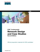
Figure C-2 illustrates how the T1 reply timer and error recovery operates for a 3174. Assume that the link between the two routers just failed. The following sequence characterizes the error recovery process illustrated in Figure C-2:

  1. The 3174 sends a data frame and starts its T1 timer.

  2. The T1 timer expires after 1.6 seconds.

  3. The 3174 goes into error recovery.

  4. The 3174 sends an LLC request (a receiver ready with the poll bit on), which requests the 3745 to immediately acknowledge this frame.

  5. The 3174 starts its T1 timer.

  6. The T1 timer expires after 1.6 seconds.

This operation is retried a total of seven times. The total elapsed time to disconnect the session is calculated as follows:

  • The first attempt plus seven retries multiplied by 1.6 seconds:

    = 8 × 1.6 seconds

    = 12.8 seconds

T1 Timer and Error Recovery Process for 3174

Figure C-2. T1 Timer and Error Recovery Process for 3174

..................Content has been hidden....................

You can't read the all page of ebook, please click here login for view all page.
Reset
18.220.235.104