Chapter 12. Wireless LAN (WLAN) Security
Wireless LAN (WLAN) network deployments are on the rise and are becoming increasingly popular because of the ease of deployment, cost effectiveness, scalability, and significant productivity gains. This rise in the recent years has offered greater mobility to users by allowing them to move freely without tangling with wired workstations. Some of the most common WLAN deployments are not secured appropriately, thereby attracting unauthorized use of the network services. The lack of trust in the security of the wireless technology has caused increasing concern when organizations are deploying WLAN-based network solutions. Organizations now demand comprehensive and secure WLAN solutions. As the leader in providing wireless networking technology, Cisco now offers comprehensive solutions to secure wireless LAN networks.
Wireless LAN (WLAN)
WLAN is a LAN that uses radio communication to provide mobility to network users while maintaining the connectivity to the wired network.
The IEEE standardizes the security for wireless-based networks into two main components: the encryption and the authentication. The following section provides a basic overview of WLANs followed by a closer look at the security features.
Radio Waves
WLAN is a LAN that transmits over the air by using radio waves that travel between the clients and access points (AP).
WLAN uses spread-spectrum technology that is based on radio waves to enable communication between devices in a limited area, also known as the basic service set. Spread spectrum technology is used both to increase the data rate and increase its tolerance to harmful interference. Spread spectrum dictates that data transmissions are spread across numerous frequencies. This gives users the capability to avoid interference from other wireless devices.
Radio waves do not require a line of sight between sender and receiver and can send or receive signals through the walls, ceilings, floors, and so on. This means that the broadcast transmission can reach unintended recipients. Therefore, strong security measures are needed to provide the same level of security as offered by wired LAN networks.
IEEE Protocol Standards
In 1990, the IEEE standards committee established a group to develop a standard for wireless communication devices. The objective was to implement wireless LAN networks (an upper-layer feature) at the data link (Layer 2) and physical layer (Layer 1) of the OSI model because they use standard interfaces into the IP layer (Layer 3). This solution provided scalability for existing operating systems and applications to be integrated into WLAN devices without modification in the upper layers.
The IEEE introduced the 802.11 family for wireless communication devices that offered the following over-the-air modulation techniques used for the wireless-based LAN technologies:
• IEEE 802.11 (The original standard defined in 1997)
• IEEE 802.11a (Defined in 1999)
• IEEE 802.11b (Defined in 1999)
• IEEE 802.11g (Defined in 2003)
• IEEE 802.11n (Under development, expected in 2007/2008)
The Wi-Fi Alliance, on the other hand, is a nonprofit, vendor-neutral organization that provides the branding for 802.11-based technology known as Wi-Fi. An 802.11-based device undergoes rigorous functionality and operational testing before it can be certified by the Wi-Fi Alliance as a compliant device to ensure the interoperability with all other Wi-Fi certified products regardless of the vendor.
Communication Method—Radio Frequency (RF)
As pointed out earlier, the WLAN is a LAN that transmits data over the air, using radio frequencies to communicate between wireless enabled devices. The transmission frequency of a WLAN depends on the IEEE protocol standard used.
The wireless-based standards take advantage of the ISM band (Industrial, Scientific, and Medical) radio spectrum that is deemed usable by the public. The 802.11 standard specifically takes advantage of the following RF bands:
• The 2.4-GHz band is used for 802.11 and 802.11b networks, providing data rates of 1 to 2 Mbps and 11 Mbps, respectively.
• The 2.4-GHz band is also used by the 802.11g networks, providing data rates of up to 54 Mbps.
• The 5.8-GHz band is used for 802.11a networks, providing data rates of 5 Mbps, 11 Mbps, and up to 54 Mbps.
• The new 802.11n standard (which is currently under development) will also be using the 2.4-GHz or 5.8-GHz band, providing data rates of up to 540 Mbps. The 802.11n standard is projected to be up to 50 times faster than 802.11b and approximately 10 times faster than the 802.11a or 802.11g.
These bands are unlicensed frequency bands (but are regulated by authorities) and are free for use by anyone without restriction as long as they comply with the regulations.
WLAN Components
WLAN networks comprise the following basic components:
• Wireless Access Point (WAP or AP): An AP is often a hardware device (but it can also be software based) that connects wireless communication devices. WAPs are commonly used to relay data between the wireless and wired network devices and other wired network resources. AP is a two-way transceiver that broadcasts data within a specific frequency spectrum. AP also performs security functions such as authentication and encryption for the wireless clients and data transmission through the wireless network.
• Wireless Network Card (NIC): A device such as a workstation or laptop requires a NIC to connect to the wireless network through radio waves. The NIC scans the available frequency spectrum for connectivity and associates the spectrum to an AP.
• Wireless bridge: Wireless bridges are optional components that are used to connect multiple LANs (wired and wireless) at the MAC-layer level. Wireless bridges can be used in building-to-building wireless scenarios, because they can cover longer distances than the normal AP. A normal AP without the wireless bridge has a coverage range of up to 1 mile, as specified by the IEEE 802.11 standards. With wireless bridges, this coverage can be extended.
• Antenna: The function of an antenna is to radiate the modulated signal through the air so that wireless clients can send and receive transmissions. Antennas are required on both the AP and the wireless client. Access points and wireless devices such as laptops usually have built-in antennas. The range and propagation characteristics of a wireless device are determined by the antenna shape and type, which can be customized for the specific application.
Figure 12-1 shows a basic setup that includes wired and wireless LAN network connections.
Figure 12-1. Wired and Wireless LAN Connected Clients
WLAN Security
Security is a top concern for all WLAN network deployments. As with any wired network, WLAN security focuses on data privacy and access control. The security of WLAN networks can be divided into two main components:
• Authentication: Strong authentication mechanisms enforce access control policy to allow authorized users to connect to the wireless network.
• Encryption: Data encryption helps ensure that only authorized recipients understand the transmitted data.
WLAN networks are widely deployed today and have become frequent targets for unauthorized access as well as a means to break into the internal network without having to connect through the wired network. WLAN networks are prone to unauthorized access as data is transmitted over the air on unlicensed frequencies, and if not encrypted, any intruder can intercept the open radio frequency range and view the data.
Using packet-sniffing software, data transmitted over the air can be easily intercepted within any unencrypted wireless network, and all contents can be viewed. In addition, the intruder can gain unauthorized access to internal networks or access to free Internet.
Most vendors are shipping wireless products with an “open-access” policy—that is, with no security features enabled by default. Although an open-access policy is suitable for public locations, such as hot spots, airports, coffee shops, and other free access zones, it is not feasible for private and enterprise networks. Wireless security features must be enabled to safeguard networks from being exposed to unauthorized access and wireless threats and attacks.
These and other security concerns have caused organizations to avoid WLAN network deployments, regardless of the numerous benefits that they provide. Securing a WLAN network is not difficult, as long as proper security solutions are selected and applied. Cisco Unified Wireless Network provides a comprehensive solution to security a WLAN network.
The following features and technologies are available to secure WLAN networks:
• Service Set Identifiers (SSID)
• MAC authentication
• Client Authentication (Open and Shared Key)
• Static WEP
• WPA, WPA2, and 802.11i (WEP enhancements)
• 802.1x and EAP
• WLAN NAC
• WLAN IPS
• VPN IPsec
Service Set Identifiers (SSID)
SSID is an arbitrary ID or name for a wireless LAN network that logically segments the subsystem. SSID provides basic access control mechanisms. All wireless devices in a specific WLAN subsystem require attachment through the SSID to bind with the WLAN network. Although SSID is not designed to be used as a security mechanism, nor does it provide data privacy or authentication, it can prevent unauthorized access to clients that do not have the valid SSID to connect to the WLAN network.
By default, an AP will broadcast its SSID in plain text to all wireless devices in the frequency range. Network sniffer tools can be used to eavesdrop on over-the-air transmission and capture SSID beacon messages to determine whether the SSID is used in the network. Therefore, it is recommended that you disable the SSID broadcast option. Network administrators should provide the SSID information to authorized wireless users to allow connection to the wireless network AP.
Although disabling the SSID broadcast may prevent someone from inadvertently connecting to your network, it is not an effective security mechanism. Disabling SSID broadcasting also breaks the Windows Wireless Zero Configuration feature. Disabling SSID does not provide complete protection from unauthorized access because some packet-sniffing software can monitor network transmission over the air to discover and learn the correct SSID in use.
MAC Authentication
Another common feature is the use of MAC address-based authentication. MAC-based authentication allows network access to known MAC addresses. The access point verifies the client MAC address against a locally configured list of allowed addresses or against an external authentication server. Access points can be preconfigured with all the wireless client MAC addresses in the MAC table that is maintained on the access point. When a client requests association to the access point, the MAC table is checked, and if the MAC address of the client matches, the authentication is successful. The client is associated to the access point and can transmit data through the AP. MAC-based authentication is very simple to configure, and most wireless vendors, including Cisco, support this feature. Note that the MAC authentication feature can be easily circumvented by using a MAC spoofing technique, in which the attacker sniffs your currently associated MAC address and spoofs it to get associated connection information, which results in an unauthorized connection. There are several techniques to combat MAC spoofing, as discussed in Chapter 7, “Attack Vectors and Mitigation Techniques.”
Note
MAC authentication is not specified in the IEEE 802.11 standard, but many vendors, including Cisco, support it.
Client Authentication (Open and Shared Key)
The IEEE 802.11 standards support the following client authentication mechanisms that provide a rudimentary level of access control:
• Open authentication: In addition to SSID, open authentication can be implemented to provide an additional layer to the access control on the access point. Open authentication involves the use of wired equivalent privacy (WEP) keys, which allow authorized clients with the correct WEP key to associate with access points and transmit and receive data through the access points.
• Shared-key authentication: Shared-key authentication is similar to open authentication, but in this case the access point sends the client a challenge packet. The client replies to the challenge packet by encrypting it with its WEP keys. If the WEP keys are correct, the access point will be able to decrypt the packet, and the client will be associated to the access point and be able to transmit and receive data through the access point. Without the correct WEP keys, authentication will fail and the client will not be able to associate with the access point. Shared-key authentication is not considered very secure because the intruder can sniff both the clear-text challenge packet and the encrypted challenge reply with a WEP key and decipher the WEP key.
Static Wired Equivalent Privacy (WEP)
Static WEP is another common type of client authentication. A static WEP key is composed of either 40 or 128 bits that is statically defined by the user on the access point and on all individual wireless clients that need to associate with the access point. This approach is not very scalable because it requires entering the static WEP key on each wireless device in the WLAN network. A static WEP key can be sniffed using tools such as AirSnort and deciphered. The attacker must capture enough packets with a weak initialization vector to computationally compute the WEP key.
WPA, WPA2, and 802.11i (WEP Enhancements)
Enhancements are required to mitigate the WEP vulnerabilities that were discussed in the previous section. The IEEE group introduced the 802.11i standard to include two encryption enhancements for all known WEP vulnerabilities in the original 802.11 security implementation:
• Temporal Key Integrity Protocol (TKIP): An IEEE 802.11i standard that provides software enhancements to the RC4-based encryption algorithm used in WEP. TKIP enhances the WEP security by adding measures such as per-packet keying (PPK), message integrity check (MIC), and broadcast key rotation to address known WEP vulnerabilities.
• Advanced Encryption Standard (AES-CCMP): An encryption protocol in the IEEE 802.11i standard upon the Counter Mode with CBC-MAC (CCM) of the AES encryption algorithm. CCM is the algorithm providing data privacy. The Cipher Block Chaining Message Authentication Code (CBC-MAC) component of CCMP provides data integrity and authentication. AES is a stronger alternative to the RC4 encryption algorithm.
These enhancements are leveraged by the new security feature WPA and WPA2. The section that follows details the WPA, WPA2, and 802.11i standard.
IEEE 802.11i defines the core security standards for WLAN networks. The IEEE 802.11i standard provides stronger encryption, authentication, and key management approaches to secure wireless data. It includes two new confidentiality protocols as mentioned previously—the TKIP and AES. Both are used for confidentiality, with a key system for each traffic type, key caching, and preauthentication mechanisms.
Wi-Fi Protected Access (WPA) is a standard security solution from the Wi-Fi Alliance that addresses all known WEP vulnerabilities in the original IEEE 802.11 security implementation and provides protection from known WLAN attacks. WPA uses the Temporal Key Integrity Protocol (TKIP) for encryption, based on the RC4 algorithm. WPA supports the preshared key (PSK) and IEEE 802.1x/EAP modes of operation for authentication. The PSK verification works via a password or a passphrase on both the client device and the access point. If the password on the client matches with the access point, verification is successful, and the client is authenticated. WPA is supported by the Cisco Unified Wireless Network solution.
WPA2 is the next generation of wireless security. It is the Wi-Fi Alliance’s interoperable implementation of the ratified IEEE 802.11i standard. WPA2 provides a stronger encryption mechanism through AES encryption algorithm using Counter Mode with Cipher Block Chaining Message Authentication Code Protocol (CCMP). WPA2 supports the PSK and IEEE 802.1x/EAP modes of operation for authentication. WPA2 is also supported by the Cisco Unified Wireless Network solution.
Both WPA and WPA2 offer a high level of assurance by providing data privacy and strong access control to restrict network access to authorized users.
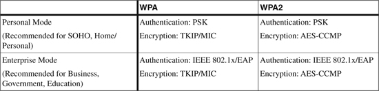
WPA and WPA2 have two operation modes. Both modes provide encryption and authentication support to meet the various needs of the different market segments (refer to Table 12-1):
• Personal Mode: Personal Mode supports wireless products by using the PSK mode of operation for authentication. A preshared key is required to be configured manually on both the access point and clients. An authentication server is not required. Personal Mode is targeted to Small Office Home Office (SOHO) environments.
• Enterprise Mode: Enterprise Mode supports wireless products by using both the PSK and IEEE 802.1x/EAP modes of operation for authentication. A AAA server using the RADIUS protocol is required when using the IEEE 802.1x mode for authentication, key management, and centralized management of user credentials. (Refer to Chapter 11, “Layer 2 Access Control,” for more details on implementing 802.1x solutions.) Enterprise Mode is targeted to enterprise environments.
Table 12-1 illustrates the summary of WPA, WPA2, and a comparison of the two operation modes.
Table 12-1. Comparison of WPA, WPA2, and the Operation Mode Types
Note
The information in Table 12-1 is taken from “Cisco LAN Security - Cisco Wi-Fi Protected Access, WPA2 AND IEEE 802.11I” at http://www.cisco.com/en/US/netsol/ns339/ns395/ns176/ns178/netqa0900aecd801e3e59.html.
Note
The Enterprise Mode of both operation modes uses IEEE 802.1x and Extensible Authentication Protocol (EAP) for authentication.
IEEE 802.1x and EAP
As discussed in Chapter 11, the Cisco IBNS solution extends network access security based on the 802.1x technology by using EAP. EAP can be used for wired and wireless LANs, but is commonly used for wireless LAN networks. The WPA and WPA2 standard officially adopts the EAP method types for authentication.
Note
RFC 4017 describes the specification and the requirements for EAP methods used in WLAN authentication.
EAP is a universal authentication framework, not a specific authentication mechanism. EAP provides common functions and communication specifications for an authentication mechanism.
These varying mechanisms are called EAP methods, and there are currently about 40 different EAP methods.
Several variations in EAP methods can be used in the 802.1x solutions to provide identity-based network access control. Choosing an EAP mechanism depends on the clients, the policy, and the existing infrastructure, as illustrated in the following questions that must be answered:
• Is there a Certificate Authority PKI infrastructure available within the network?
• What client platforms are supported within the network?
• Is there any existing authentication system?
• Is there a requirement to support multiple EAP mechanisms?
The following sections describe support for some of the common EAP methods used in access control solutions:
• EAP Message Digest 5 (EAP-MD5)
• EAP Transport Level Security (EAP-TLS)
• EAP Tunneled Transport Level Security (EAP-TTLS)
• EAP Flexible Authentication via Secure Tunneling (EAP-FAST)
• Protected EAP (PEAP)
• Cisco Lightweight Extensible Authentication Protocol (Cisco-LEAP)
EAP Message Digest 5 (EAP-MD5)
EAP-MD5 (Extensible Authentication Protocol-Message Digest 5) is one of the IETF open standard, nonproprietary EAP types. EAP-MD5 is popular because of the ease of deployment. However, it is not one of the most secure EAP types because the MD5 hash function is susceptible to various attacks, such as offline dictionary attacks. EAP-MD5 does not support mutual authentication or key generation, which makes it unsuitable for use with dynamic WEP, WPA, or WPA2 environments.
EAP is defined in RFC 3748 (which replaces RFC 2284). MD5 is defined in RFC 1321.
The following list outlines the authentication process that takes place when an IEEE 802.1x supplicant connects to the wireless network using the EAP-MD5 authentication method. Figure 12-2 illustrates the EAP-MD5 message exchange between the client supplicant, the authenticator (switch or access point), and the authentication server (RADIUS), as explained in the list that follows.
Figure 12-2. EAP-MD5 Message Exchange
1 An IEEE 802.1x supplicant client initiates a connection request to the network by sending an EAPoL (EAP over LAN) Start message to the authenticator (Switch or Access Point).
2 The authenticator sends an EAP Identity Request message to the client.
3 The client replies with an EAP Identity Response to the authenticator.
4 The authenticator forwards the EAP Identity Response message to the authentication server encapsulated in the RADIUS protocol.
5 The authentication server sends an MD5 Challenge Request that is forwarded to the client by the authenticator.
6 The client replies with a Challenge Response message to the server.
7 The authentication server validates the user identity and sends an EAP Success or Fail message to the client.
8 Based on the authentication server reply (Pass or Fail), the authenticator enables the port connected to the client.
EAP Transport Layer Security (EAP-TLS)
Extensible Authentication Protocol-Transport Layer Security (EAP-TLS) is another open standard IETF standard, which is developed by Microsoft Corporation as an extension of Point-to-Point Protocol (PPP) to provide authentication within PPP, with TLS providing integrity of negotiation and key exchange. EAP-TLS provides greater security by using TLS, which is considered the successor of the SSL standard and therefore one of the most secure EAP methods available.
EAP-TLS offers per-packet confidentiality and integrity to protect identification and a standardized mechanism for key exchange.
EAP-TLS uses the X.509 PKI infrastructure to provide certificate-based 802.1x port-based access control. EAP-TLS addresses a number of weaknesses in other EAP protocols such as EAP-MD5.
Deployment of EAP-TLS increases in complexity because it requires mutual authentication, negotiation of encryption methods, and, most important, requires installing certificates on the client supplicant and server.
EAP-TLS is defined in RFC 2716.
The following authentication process takes place when an IEEE 802.1x supplicant connects to the wireless network by using the EAP-TLS authentication method. Figure 12-3 illustrates the EAP-TLS message exchange between the client supplicant, the authenticator (switch or access point), and the authentication server (RADIUS), as explained in the list that follows.
Figure 12-3. EAP-TLS Message Exchange
1 An IEEE 802.1x supplicant client initiates a connection request to the network by sending an EAPoL Start message to the authenticator (Switch or Access Point).
2 The authenticator sends an EAP Identity Request message to the client.
3 The client replies with an EAP Identity Response to the authenticator.
4 The authenticator forwards the EAP Identity Response message to the authentication server encapsulated in RADIUS protocol.
5 The authentication server sends an EAP-TLS Start message to the client.
6 The client replies with an EAP-TLS Client Hello message.
7 The authentication server replies with an EAP-TLS Server Hello message and includes its own server certificate and requests for the client’s certificate.
8 The client verifies the server certificate using the server public key, sends the client certificate to the server, and sends the cipher trust protocol set.
9 The server verifies the client certificate, confirms the cipher trust protocol set, and validates the client credentials.
10 TLS tunnel is established and sends an EAP Success or Fail message to the client via the protected tunnel.
11 Based on the authentication server reply (Pass or Fail), the authenticator enables the port connected to the client.
EAP Tunneled Transport Layer Security (EAP-TTLS)
EAP-TTLS was codeveloped by Funk Software and Certicom. EAP-TTLS is widely supported across wireless platforms because it offers the same level of security and integrity as EAP-TLS without the overhead of installing PKI certificates on the client. EAP-TTLS requires a server-side certificate only on the authentication server. Note that despite the fact that EAP-TTLS requires only a certificate on the server side, the server is still able to authenticate the client after the secure tunnel has been established.
EAP-TTLS is described in an IETF Internet draft “draft-funk-eap-ttls-v1-01.txt.” The draft can be found at http://tools.ietf.org/id/draft-funk-eap-ttls-v1-01.txt.
Here is a snippet from the abstract of the Internet draft:
“EAP-TTLS is an EAP type that utilizes TLS to establish a secure connection between a client and server, through which additional information may be exchanged. The initial TLS handshake may mutually authenticate client and server; or it may perform a one-way authentication, in which only the server is authenticated to the client.”
Note
EAP-TTLS is an individual draft submission and is not standardized in the IETF.
EAP Flexible Authentication via Secure Tunneling (EAP-FAST)
Extensible Authentication Protocol-Flexible Authentication via Secure Tunneling (EAP-FAST) was developed by Cisco Systems, and an initial draft was submitted to the IETF in February 2004. The draft was revised and resubmitted in April 2005. EAP-FAST was developed to address the weaknesses of LEAP.
EAP-FAST uses the TLS tunnel, thereby providing a strong level of encryption. Similar to other EAP types that use the TLS approach, EAP-FAST offers confidentiality and integrity to protect user identification.
Although the concept is similar to other EAP types using TLS tunnel, the major differentiator is that EAP-FAST does not use the PKI infrastructure for user identity (server certificate is optional) to establish the tunnel. The client server architecture in EAP-FAST is based on strong shared secret keys that are unique on every client. These shared secret keys are called Protected Access Credential (PAC). The shared secret keys are distributed automatically to the client device via in-band provisioning or manually via out-band provisioning.
EAP-FAST is significantly faster because of the PAC architecture that expedites the tunnel establishment. Tunnel establishment using a shared secret key is inherently faster than using a PKI certificate-based exchange method. EAP-FAST remains popular among the other EAP-based solutions that provide encrypted EAP transactions.
EAP-FAST negotiation occurs in two phases:
• In Phase 1, the supplicant client and the authentication server perform mutual authentication using the PAC and establish the TLS tunnel.
• In Phase 2, the client exchanges the user credentials using the protected tunnel.
Figure 12-4 shows the details of the Phase 1 and 2 message exchange.
The following authentication process takes place when an IEEE 802.1x supplicant connects to the wireless network by employing EAP-FAST using the EAP-GTC (Generic Token Card) authentication method that is embedded in a TLS-protected tunnel. Figure 12-4 illustrates the EAP-FAST message exchange between the client supplicant, the authenticator (switch or access point), and the authentication server (RADIUS), as explained next:
1 An IEEE 802.1x supplicant client initiates a connection request to the network by sending an EAPoL Start message to the authenticator (Switch or Access Point).
2 The authenticator sends an EAP Identity Request message to the client.
3 The client replies with an EAP Identity Response to the authenticator.
4 The authenticator forwards the EAP Identity Response message to the authentication server, encapsulated in the RADIUS protocol.
5 The authentication server sends an EAP-TLS Start message to the client.
6 The authentication server sends an EAP-FAST Start message to the client, which includes the Authority ID.
Figure 12-4. EAP-FAST Message Exchange
7 The client sends an EAP-TLS Client Hello message and selects a stored PAC key (a unique shared secret key based on the received Authority ID). The client also sends a PAC Opaque reply to the server (based on the PAC key selected).
8 The authentication server decrypts the PAC Opaque key by using the master key to derive the PAC key and sends an EAP-TLS Server Hello message and the cipher trust protocol set.
9 The client confirms the cipher trust protocol set.
10 When the PAC keys match on both ends, mutual authentication is successful and the TLS tunnel is established.
11 After the TLS tunnel is established, the server sends an authentication request using the EAP-GTC request via the protected tunnel.
12 The client sends an authentication response message to the EAP-GTC authentication via the tunnel.
13 The server verifies the client identity and sends an EAP Success or Fail message to the client via the protected tunnel.
14 Based on the authentication server reply (Pass or Fail), the authenticator enables the port connected to the client.
Protected EAP (PEAP)
Protected Extensible Authentication Protocol (PEAP) is another open standard EAP type that was jointly developed by Cisco Systems, Microsoft Corporation, and RSA Security.
PEAP is a hybrid authentication protocol that creates a secured TLS tunnel and design architecture that is similar to EAP-TTLS discussed earlier. To establish the TLS tunnel, both PEAP and EAP-TTLS require server-side certificates only. PEAP is unique in that any EAP method type can be encapsulated in a TLS tunnel to provide a secure connection between the client and server.
To date, the following two PEAP subtypes are certified for the WPA and WPA2 standard:
• PEAPv0 with EAP-MSCHAPv2
• PEAPv1 with EAP-GTC
As shown in Figure 12-5, PEAP establishes the TLS tunnel in Phase 1, thereby creating a secure channel that can then be used to initiate any other EAP type that uses the protected tunnel in Phase 2. Theoretically, any EAP type can be wrapped within the TLS tunnel.
As discussed in the EAP-MD5 section and shown in Figure 12-2, challenge authentication and negotiation is in clear text without encryption. Although challenge exchange provides better protection, it is still susceptible to offline dictionary attacks. With PEAP, challenge exchange is protected with the strong security of the TLS channel.
The authentication processes outlined in the steps that follow take place when an IEEE 802.1x supplicant connects to the wireless network by using the PEAP-MSCHAPv2 authentication method. Figure 12-5 illustrates the PEAP message exchange among the client supplicant, the authenticator (switch or access point), and the authentication server (RADIUS), as explained in the list that follows.
Figure 12-5. PEAP with EAP-MSCHAPv2 Message Exchange
1 An IEEE 802.1x supplicant client initiates a connection request to the network by sending an EAPoL Start message to the authenticator (Switch or Access Point).
2 The authenticator sends an EAP Identity Request message to the client.
3 The client replies with an EAP Identity Response to the authenticator.
4 The authenticator forwards the EAP Identity Response message to the authentication server encapsulated in the RADIUS protocol.
5 The authentication server sends an EAP-TLS Start message to the client.
6 The client replies with an EAP-TLS Client Hello message.
7 The authentication server replies with an EAP-TLS Server Hello message and sends the server certificate to the client. (Note that no client certificate is requested.)
8 The client verifies the server certificate using the server public key and sends the cipher trust protocol set.
9 The server confirms that the cipher trust protocol and TLS tunnel is established.
10 The authenticator sends an EAP Identity Request message to the client.
11 The client replies with an EAP Identity Response to the authenticator via the protected tunnel.
12 The authentication server sends a Challenge Request via the protected tunnel.
13 The client replies with a Challenge Response message to the server via the protected tunnel.
14 The Authentication Server validates the user identity and sends an EAP Success or Fail message to the client via the protected tunnel.
15 Based on the authentication server reply (Pass or Fail), the authenticator enables the port connected to the client.
Cisco Lightweight EAP (LEAP)
Lightweight Extensible Authentication Protocol (LEAP) is a Cisco proprietary EAP method.
Cisco was a pioneer in introducing EAP support for WLAN devices. Cisco introduced LEAP in 2000 offering the first WLAN authentication method.
Cisco LEAP is a mutual authentication algorithm that uses a logon password as the shared secret that is known by the client and is used to respond to the challenges between the client and the authentication server. LEAP provides dynamic per-user, per-session encryption keys.
Most password-based authentication algorithms are susceptible to dictionary attacks, and the most effective way to safeguard against dictionary attacks is to create a strong password policy. Because Cisco LEAP uses password-based authentication, Cisco LEAP is also known to be susceptible to offline dictionary attacks, just like any other EAP type that uses a challenge response. At the DEFCON convention in 2003, a presentation was delivered that explored mechanisms that could make it easier for someone to write a tool to launch an offline dictionary attack on password-based authentications that leverage Microsoft MS-CHAP.
Cisco published a white paper, which is available on Cisco.com, to respond to the offline dictionary attacks on Cisco LEAP. EAP-FAST is one of the Cisco-suggested EAP methods to mitigate the offline dictionary attacks against MS-CHAP in LEAP.
Note
“Cisco Response to Dictionary Attacks on Cisco LEAP” can be found at http://www.cisco.com/en/US/products/hw/wireless/ps430/prod_bulletin09186a00801cc901.html.
Newer protocols such as EAP-TTLS and PEAP do not have this problem, because the challenge response is tunneled within a secure encrypted TLS tunnel.
EAP Comparison Chart
Table 12-2 provides a summary comparison of PEAP, EAP-FAST, Cisco LEAP, and EAP-TLS standards.
Table 12-2. Comparison Chart of PEAP, EAP-FAST, Cisco LEAP, and EAP-TLS
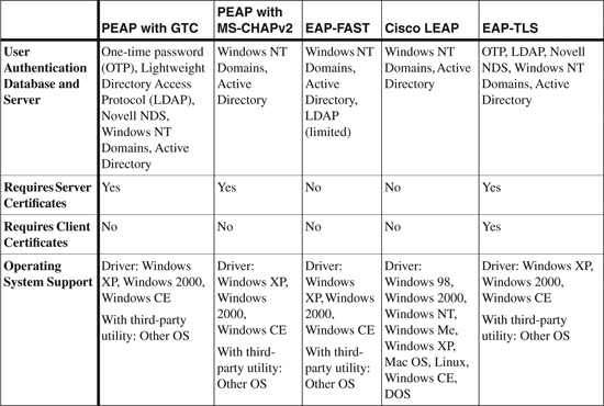
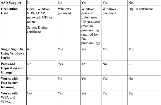
Note
The information in Table 12-2 is taken from “Cisco Aironet 1200 Series – Q&A” at http://www.cisco.com/en/US/products/hw/wireless/ps430/products_qanda_item0900aecd801764fa.shtml.
WLAN NAC
Network Admission Control (NAC) for WLANs is a set of technologies and solutions used to enforce security policy compliance on all devices seeking network access and resources, thereby limiting damage from emerging security threats.
NAC is an industry initiative led by Cisco Systems and is part of the Cisco Self-Defending Network initiative that improves the network’s capability to automatically identify, prevent, and adapt to security threats.
The WLAN NAC solution is available with the Cisco Unified Wireless Network solution.
WLAN IPS
Cisco Access Points offer an Intrusion Prevention System (IPS) for WLANs to provide intrusion detection capability while simultaneously forwarding data over the air. This allows an access point to monitor real-time wireless data, scanning for potential security threats to wireless devices. At this time, Cisco is the only vendor providing a WLAN solution that offers simultaneous wireless protection and data delivery.
WLAN IPS is part of the Cisco Self-Defending Network initiative, and is the first in the industry to offer an integrated wired and wireless IPS security solution.
A WLAN IPS solution is available with the Cisco Unified Wireless Network solution.
Note
Refer to the following white paper for integrating IPS to address wireless threats:
VPN IPsec
Virtual Private Network IP Security (VPN IPsec) is a framework and architecture of open standards for ensuring secure private communications over IP networks. VPN IPsec offers the confidentiality, integrity, and authenticity of data communications across shared or public networks.
IPsec can also be used as a solution (out-of-band) to secure WLAN traffic that is encapsulated in the IPsec tunnel.
Mitigating WLAN Attacks
A variety of attacks can be launched against WLAN networks. Both WPA and WPA2 devices offer protection to the network from a variety of network attacks when IEEE 802.1x, EAP types, and TKIP and AES are used. Table 12-3 shows a list of common attacks and the EAP enhancements that are used to protect against known attacks.
Table 12-3. WLAN Attack Mitigation
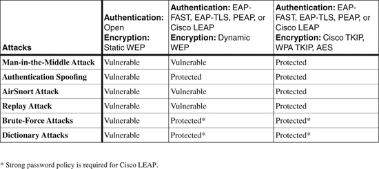
Note
The information in Table 12-3 is taken from “Cisco Wireless LAN Security Overview” at http://www.cisco.com/en/US/products/hw/wireless/ps430/prod_brochure09186a00801f7d0b.html.
Cisco Unified Wireless Network Solution
The Cisco Unified Wireless Network offers a secure WLAN solution by combining the best-of-breed wireless standards and specifications to fulfill the need for scalable, reliable, and secure wireless networking and security services.
The Cisco Unified Wireless Network delivers the same level of security, scalability, reliability, ease of deployment, and management for wireless LAN networks that is offered by any other wired LAN solution.
The Cisco Unified Wireless Network solution offers all the WLAN security features that were discussed previously in this chapter and provides comprehensive WLAN attack mitigation, as described in Table 12-3.
Some of the common security features offered by Cisco Unified Wireless Network solution are
• Enterprise-ready, standards-based WLAN network
• Support of IEEE 802.11 standards
• SSID, MAC authentication, and other common techniques
• Support for WPA, WPA2, and 802.11i
• Mutual authentication mechanisms
• Support for IEEE 802.1x and various EAP methods
• Support for TKIP and AES
• Support of Wireless NAC
• Support of Wireless IPS
• Support for radio resource management (RRM) to monitor over-the-air packets and alert the network management console of different types of threats, such as rogue access points, rogue clients, ad hoc networks, and wireless DoS attacks
• Addressing of known wireless attacks and provision of mitigation techniques
• Support of Management Frame Protection (MFP) for 802.11 management attack mitigation
Components of Cisco Unified Wireless Network
The Cisco Unified Wireless Network is composed of five interconnected elements that work together to deliver a unified enterprise-class wireless solution. The five interconnected elements are
• Client devices
• Access points
• Network unification
• Network management
• Mobility services
Note
Cisco offers a wide range of WLAN products to support the five interconnecting elements of the Cisco Unified Wireless Network solution.
Refer to the following website for further information on the Cisco Unified Wireless Network solution, features, benefits, and in-depth details about each of the five elements:
http://www.cisco.com/en/US/products/ps6521/prod_brochure09186a0080184925.html
Cisco Unified Wireless Network solution provides a comprehensive integrated security solution to protect WLAN networks.
Tip
In addition to the WLAN security features discussed in this chapter, refer to the following link on Cisco.com for white papers on WLAN Security Solutions: http://www.cisco.com/en/US/netsol/ns340/ns394/ns348/ns386/networking_solutions_white_papers_list.html.
Summary
WLANs are increasingly deployed throughout organizations to provide greater mobility, scalability, and productivity.
Securing WLANs has always been considered difficult because of the variety of available solutions with varying standards. Cisco, one of the pioneers and leaders in providing wireless networking technology, now offers comprehensive solutions to secure WLANs.
The chapter started with a brief introduction and overview of WLAN, providing details of various IEEE 802.11 protocol standards and details of various WLAN components.
The major portion of the chapter provided detailed sections of various WLAN security features that are available to secure WLANs. Features covered include SSID, MAC authentication, Client authentication (Open and Shared Key), Static WEP, WPA/WPA2, 802.1x, EAP methods, WLAN NAC, WLAN IPS, and IPsec VPN.
The chapter provided a comparison chart of various EAP methods and another table showing a list of common attacks and the EAP enhancements used to protect against known attacks.
The chapter concluded with an overview of the Cisco Unified Wireless Network solution that provides a comprehensive integrated security solution to protect WLANs.
References
http://www.cisco.com/en/US/products/hw/wireless/ps430/prod_brochure09186a00801f7d0b.html
http://www.answers.com/topic/wireless-lan-security
http://en.wikipedia.org/wiki/Extensible_Authentication_Protocol
http://www.cisco.com/en/US/netsol/ns339/ns395/ns176/ns178/netqa0900aecd801e3e59.html
http://www.cisco.com/en/US/products/hw/wireless/ps430/products_qanda_item0900aecd801764f1.shtml
http://www.cisco.com/en/US/products/ps6521/prod_brochure0900aecd80355b2f.html
http://www.cisco.com/en/US/products/ps6548/products_white_paper0900aecd804f155b.shtml
http://www.cisco.com/en/US/netsol/ns340/ns394/ns348/ns337/networking_solutions_package.html
http://www.cisco.com/en/US/products/ps6521/prod_brochure09186a0080184925.html