Chapter 19. Multiprotocol Label Switching VPN (MPLS VPN)
Multiprotocol Label Switching (MPLS) is a widely used transport mechanism that carries data traffic over a packet-switched network (PSN).
MPLS VPN is a service solution extension of the MPLS for providing VPN services that allows enterprises and service providers to build highly efficient, scalable, and secure next-generation intelligent networks.
This chapter provides an overview of MPLS VPN architecture and a basic understanding of the various types of MPLS VPNs. The chapter also covers the Cisco Layer 2 VPN (L2VPN) and Layer 3 VPN (L3VPN) solutions.
Multiprotocol Label Switching (MPLS)
MPLS is a transport mechanism that carries data over a packet-switched network. MPLS is widely used by service providers and large-scale enterprise networks.
MPLS framework was designed to provide flexibility to operate with virtually any Layer 3 and Layer 2 technology. MPLS-based solutions can be integrated seamlessly over any existing infrastructure.
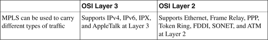
MPLS supports several Layer 3 and Layer 2 protocols. Table 19-1 shows a list of commonly supported protocols.
Table 19-1. MPLS Supported Protocols
MPLS was originally a Cisco proprietary technology called tag switching—a solution designed by a group of Cisco engineers. It was later handed over to the IETF for open standardization and was renamed label switching.
Tip
MPLS working documents, Internet-draft papers, and RFCs can be downloaded from the following Internet Engineering Task Force (IETF)–based MPLS working group website:
MPLS Architecture Overview
The MPLS architecture defines the basic mechanism for performing label switching within an MPLS core network.
MPLS combines the benefits of packet forwarding based on connection-oriented Layer 2 switching with connectionless Layer 3 routing.
The advantage of this architecture is that routers at the network edge can use conventional IP forwarding, whereas routers in the network core can run MPLS and use switching instead of conventional routing table lookup. This also simplifies the hop-by-hop data forwarding path by replacing the Layer 3 route lookup function performed in traditional routers with a label swapping mechanism, thus providing faster packet forwarding and improved network performance.
MPLS architecture assigns labels to each packet to be able to transport them across the MPLS core network. The concept of label is similar to other Layer 2 technologies, such as Frame Relay or ATM. Labels are used to perform the next-hop label lookup at Layer 2 to traverse the network. Each node within the network processes the label on the incoming packet, swaps the label with a new label at outgoing (label swapping), and forwards the packet to the next node.
The new advanced label-swapping technique in MPLS improves the network performance and provides greater scalability and flexibility in the delivery of routing services.
Figure 19-1 illustrates the MPLS core architecture.
How MPLS Works
When a packet arrives on the ingress Label Switch Router (LSR), also called the Provider Edge (PE) router, the PE router assigns a label to transport the packet through the MPLS network.
As shown in Figure 19-2, each LSR performs a specific function; for example, the LSR at the edge performs either label imposition (also known as the push functions) or label removing (also known as the pop function). Other LSRs in the path simply swap the labels.
Figure 19-1. MPLS Packet Forwarding Architecture
Each LSR maintains a Label Forwarding Information Base (LFIB) table that is built using the IP routing table to determine the label binding exchange. The LFIB provides an incoming labeled packet with the outgoing interface and the new label information associated respectively with the outgoing packet.
Adjacent nodes perform a label binding exchange for individual subnets (destination-based IP routing) using the Cisco proprietary Tag Distribution Protocol (TDP) or the IETF-standard Label Distribution Protocol (LDP). If the route (prefix/mask and next hop) learned via the TDP/LDP matches the route learned via IGP in the routing table, an entry is created in the LFIB on the LSR.
Packets in the MPLS core are forwarded based on the labels that are prepended by the LSR, and not based on the IP destination address.
The LSR-to-LSR journey of this packet within the MPLS core crosses several LSR routers; this path is called the Label Switched Path (LSP). LSP is essentially a set of LSRs (similar to the AS path in BGP) through which a labeled packet must traverse to reach the edge LSR. As a packet traverses the LSP, each LSR swaps the label until it reaches the router before the last LSR (the penultimate hop), which pops the label and transmits the packet without the label to the last hop egress LSR, where the packet is out of the MPLS core and forwarded to the destination CE.
Figure 19-2 shows a detailed diagram demonstrating how the packet forwarding and label swapping works within the MPLS core network.
Figure 19-2. MPLS Packet Forwarding and Label Switching
MPLS VPN and IPsec VPN
MPLS VPN and IPsec VPN are complementary technologies; both have their benefits, though in different implementations.
The MPLS VPN solution provides a pseudo point-to-point connection that allows networks to peer indirectly, providing a sense of security and data privacy. MPLS VPN creates a private data path through the MPLS core network, providing faster and more secure data paths without network overhead.
MPLS VPN does not provide data confidentiality or cryptography functions. This means that data could possibly be intercepted during transmission without sender/receiver knowledge. Thus, it will often not meet requirements for confidentiality or nonrepudiation that may be required by some of the industry standards (for example, HIPAA). The security must be provided at the network layer. To provide data confidentiality, IPsec VPN solution at the network layer can be deployed as an overlay over the MPLS network.
Table 19-2 shows a comparison between MPLS VPN and IPsec VPN technologies.
Table 19-2. Comparison Between MPLS VPN and IPsec VPN
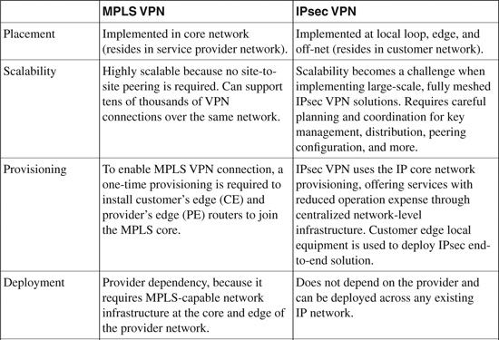
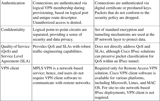
Note: The information in Table 19-2 is compiled from the Cisco white paper on “VPN Architectures - Comparing MPLS and IPsec” at http://www.cisco.com/en/US/netsol/ns590/networking_solutions_white_paper09186a008009d67f.shtml.
Deployment Scenarios
There are three basic deployment scenarios for implementing MPLS solutions, as shown in Figure 19-3.
• Shared Core and Shared Edge: This design comprises a single MPLS core that services both the public IP and private VPN traffic. Similarly at the edge, a single PE router is used to terminate both public IP and private VPN connections.
• Shared Core and Separate Edge: This design also comprises a single MPLS core that services both the public IP and private VPN traffic. At the edge, dedicated, purpose-built PE routers are used to terminate public IP and private VPN connections, respectively.
• Separate Core and Separate Edge: This design comprises separate MPLS cores for each public IP and private VPN traffic connections, respectively. Similarly at the edge, dedicated PE routers (purpose-built) are used to terminate public IP and private VPN connections, respectively.
Figure 19-3. MPLS Deployment Scenarios
Note
The information in Figure 19-3 is compiled from the Cisco Networkers session presentation# SEC-2100 – “MPLS-VPN Security Guidelines.”
Connection-Oriented and Connectionless VPN Technologies
VPN technologies vary, and there is no fixed classification for VPN solutions. VPN can be categorized in two ways: connection-oriented and connectionless VPN. As shown in Figure 19-4, connection-oriented VPN has an end-to-end path through the core network. Examples include IPsec and generic routing encapsulation (GRE).
Connectionless VPN does not have a direct relationship with a peer site and has a virtual path joining two sites via the core network. Examples include MPLS VPN, which connects two customer sites via the MPLS core cloud.
Connectionless VPNs scale better because less information is kept at the customer edge, whereas with connection-oriented VPNs, all information is kept at the edge. Figure 19-4 illustrates the connection-oriented and connectionless VPN technologies.
Figure 19-4. Connection-Oriented and Connectionless VPN Technologies
MPLS VPN (Trusted VPN)
As discussed in Chapter 15, “IPsec VPN,” there are two major types of VPNs:
• Secure VPN (also known as Cryptographic VPN): Secure VPN technologies include IPsec, L2TP over IPsec, and Secure Sockets Layer (SSL) encryption.
• Trusted VPN (also known as non-Cryptographic VPN): Trusted VPN technologies include Multiprotocol Label Switching (MPLS) VPN (Layer 3 VPN), Multicast VPN (Layer 3 VPN), Transport of Layer 2 frames over MPLS, Any Transport over MPLS (AToM) (Layer 2 VPN), and virtual private LAN services (VPLS) (Layer 2 VPN).
Note
Secure VPN technologies are covered in Chapters 15, 16, 17, and 18. This section covers Trusted VPN technologies.
The major characteristic of Trusted VPN is based on the service provider offering a dedicated circuit or channel to a customer. Hence, pseudo point-to-point communication occurs in this scenario, allowing networks to peer directly using a dedicated circuit and providing a sense of security and data privacy. Traffic traversing this dedicated point-to-point circuit is called Trusted VPN.
In a Trusted VPN, security relies on the fact that the circuit provided by the service provider is not shared and is dedicated to a single site for point-to-point communication between specific customer sites.
Service providers today offer several Trusted VPN services. There are two major types of Trusted VPNs:
• Layer 3 VPN (L3VPN): Packet-based forwarding
• Layer 2 VPN (L2VPN): Frame-based forwarding
Comparison of L3 and L2 VPNs
Table 19-3 shows a basic comparison between L3VPN and L2VPN solutions and describes the type of data each can carry.
Table 19-3. Comparison Between L3VPN and L2VPN
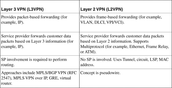
Selecting L3VPN over L2VPN depends on how much control the enterprise wants to retain within its network. With L3VPN, the service provider is involved because it performs the routing; whereas with L2VPN, the service provider is not involved, because virtual tunnels and circuits are used instead.
Subscribers have various requirements and can take advantage of L3VPN and L2VPN as needed.
• L3VPN is useful to subscribers who prefer to outsource their routing to service providers. The service provider manages routing for the customer’s sites.
• L2VPN is useful to subscribers who run their own Layer 3 networks over the WAN and require Layer 2 connectivity from service providers. In this case, the subscriber manages its own routing information.
Figure 19-5 illustrates the Layer 3 and Layer 2 VPN data forwarding scenarios over the MPLS core. Both Layer 3 and Layer 2 VPN services are offered from the edge of a network.
Figure 19-5. Layer 3 Versus Layer 2 VPN Forwarding
Layer 3 VPN (L3VPN)
Layer 3 VPN (L3VPN) over MPLS is one of the most widely deployed MPLS applications in service provider and large-scale enterprise networks.
Cisco IOS Software supports L3VPN architecture that uses the RFC 2547 standard implementation to provide a secure and robust VPN solution offering any-to-any connectivity that can be implemented over MPLS or IP network infrastructure.
L3VPN architecture leverages Multiprotocol Border Gateway Protocol (MP-BGP) and Virtual Routing and Forwarding (VRF) instances to constitute a peer-to-peer VPN framework via the IP/MPLS core network. This model allows enterprise networks to outsource routing table information to service providers.
L3VPN allows service providers to offer additional value-add services to the customers, such as QoS, Traffic Engineering (TE), and Fast Reroute services, thereby reducing operational costs and complexity, and increasing network performance and convergence.
Components of L3VPN
There are three major components in an L3VPN network:
• VPN Route Target Communities: This consists of a list of all members of the VPN community. VPN route targets need to be configured for each VPN community member.
• Multiprotocol BGP (MP-BGP) Peering: This is configured between all PE routers within a VPN community. MP-BGP is used to propagate VRF reachability information to all members of a VPN community.
• MPLS Forwarding: MPLS core transports all traffic between all VPN community members across a VPN service-provider core network.
As mentioned earlier, MPLS VPN is a connection-less technology; hence, it does not require a one-to-one relationship between customer sites and VPNs. A given customer site can be a member of multiple VPNs. However, each site can associate with only one VRF. VRF ensures a customer site gets all the routes pertaining to the site from the VPNs of which it is a member.
How L3VPN Implementation Works
L3VPN is implemented at the edge of an MPLS core network on the PE (provider’s edge) router. The PE router is responsible for the following:
• Exchange routing updates with the CE (Customer’s Edge) router
• Translate the CE routing information into VPNv4 routes
• Exchange VPNv4 routes with other PE routers via the MP-BGP through the MPLS core
How VRF Tables Work
Virtual Routing and Forwarding (VRF) constitutes the VPN membership of a customer site that is attached to a PE router. Each VPN can be associated with one or more VRF instances. A VRF consists of the following components:
• IP routing table
• Derived CEF table
• Set of interfaces that use the forwarding table
• Set of rules and routing protocol parameters that control the information that is included in the routing table
VRF tables are used to forward packets within a VPN. Each VRF instance maintains a separate set of routing and CEF tables. This segregation prevents leaking of routes outside a VPN and ensures that packets outside a VPN are not forwarded to any router within the VPN.
VPN routing information is distributed through the MPLS core using VPN route target communities that are implemented by MP-BGP extended communities.
Implementing L3VPN
Figure 19-6 topology demonstrates a basic L3VPN scenario using MP-BGP. The MPLS core interconnects VPN sites as shown in Figure 19-6. The customer CE router is a member of two VPNs (VPN_A and VPN_B) on each site with overlapping subnets. Intermediate System-to-Intermediate System (IS-IS) protocol is running within the MPLS core network.
Figure 19-6. Implementing Basic L3VPN (MPLS VPN Using MP-BGP)
Based on the Figure 19-6 illustration, the following configuration examples provide deployment guidelines for implementing basic MPLS L3VPN solutions.
Example 19-1 shows PE-1 configuration
Example 19-2 shows PE-2 configuration
Example 19-3 shows P-1 configuration
Example 19-4 shows P-2 configuration
Example 19-1. Configuring L3VPN on Cisco IOS Router—PE-1 LSR
hostname PE1
!
ip cef
!
!--- VPN A commands.
!
ip vrf VPN_A
!--- Enables the VPN routing and forwarding (VRF) routing table.
!
rd 100:111
!--- Route distinguisher creates routing and forwarding tables for a VRF.
route-target export 100:111
route-target import 100:111
!--- Creates lists of import and export route-target extended. communities for the
specified VRF.
!
!
!
!--- VPN B commands.
!
ip vrf VPN_B
rd 100:222
route-target export 100:222
route-target import 100:222
!
interface Loopback0
ip address 10.10.10.1 255.255.255.255
ip router isis
!
!--- VPN A commands.
!
interface Looback1
ip vrf forwarding VPN_A
!--- Associates a VRF instance with an interface or subinterface.
ip address 100.0.1.1 255.255.255.0
!--- Looback1 and Loopback2 use the same IP address 100.0.1.1
!--- Duplicate subnets are allowed because they belong to two different VRF
no ip directed-broadcast
!
!
!
!--- VPN B commands.
!
interface Looback2
ip vrf forwarding VPN_B
ip address 100.0.1.1 255.255.255.0
!--- Looback1 and Loopback2 use the same IP address 100.0.1.1
!--- Duplicate subnets are allowed because they belong to two different VRF
no ip directed-broadcast
!
interface Serial2/0
no ip address
no ip directed-broadcast
encapsulation frame-relay
no fair-queue
!
interface Serial2/0.1 point-to-point
description link to P1
bandwidth 512
ip address 10.1.1.1 255.255.255.252
no ip directed-broadcast
ip router isis
tag-switching ip
frame-relay interface-dlci 101
!
router isis
net 49.0001.0000.0000.0004.00
is-type level-1
!
router bgp 100
bgp log-neighbor-changes
neighbor 10.10.10.2 remote-as 100
neighbor 10.10.10.2 update-source Loopback0
!
!
!--- VPN A and B commands
address-family vpnv4
neighbor 10.10.10.2 activate
neighbor 10.10.10.2 send-community both
exit-address-family
!
!
!
!--- VPN A commands
address-family ipv4 vrf VPN_A
redistribute connected
no auto-summary
no synchronization
exit-address-family
!
!
!
!--- VPN B commands
address-family ipv4 vrf VPN_B
redistribute connected
no auto-summary
no synchronization
exit-address-family
!
!
!
ip classless
!
end
Example 19-2. Configuring L3VPN on Cisco IOS Router—PE-2 LSR
hostname PE2
!
ip cef
!
!--- VPN A commands
!
ip vrf VPN_A
rd 100:111
route-target export 100:111
route-target import 100:111
!
!--- VPN B commands.
!
ip vrf VPN_B
rd 100:222
route-target export 100:222
route-target import 100:222
!
interface Loopback0
ip address 10.10.10.2 255.255.255.255
ip router isis
!
!--- VPN A commands
!
interface Looback1
ip vrf forwarding VPN_A
ip address 100.0.2.1 255.255.255.0
!--- Looback1 and Loopback2 use the same IP address 100.0.2.1
!--- Duplicate subnets are allowed because they belong to two different VRF
!
!
!--- VPN B commands
!
interface Looback2
ip vrf forwarding VPN_B
ip address 100.0.2.1 255.255.255.0
!--- Looback1 and Loopback2 use the same IP address 100.0.2.1
!--- Duplicate subnets are allowed because they belong to two different VRF
!
!
interface Serial0/0
no ip address
encapsulation frame-relay
no ip mroute-cache
!
interface Serial0/0.1 point-to-point
description link to P2
bandwidth 512
ip address 10.1.1.10 255.255.255.252
ip router isis
tag-switching ip
frame-relay interface-dlci 403
!
router isis
net 49.0001.0000.0000.0006.00
is-type level-1
!
router bgp 100
neighbor 10.10.10.1 remote-as 100
neighbor 10.10.10.1 update-source Loopback0
!
!
!
!--- VPN A and B commands
!
address-family vpnv4
neighbor 10.10.10.1 activate
neighbor 10.10.10.1 send-community both
exit-address-family
!
!
!--- VPN A commands
!
address-family ipv4 vrf VPN_A
redistribute connected
no auto-summary
no synchronization
exit-address-family
!
!
!--- VPN B commands
!
address-family ipv4 vrf VPN_B
redistribute connected
no auto-summary
no synchronization
exit-address-family
!
!
ip classless
!
end
Example 19-3. Configuring L3VPN on Cisco IOS Router—P-1 LSR
hostname P1
!
ip cef
!
interface Loopback0
ip address 10.10.10.3 255.255.255.255
ip router isis
!
interface Serial0/0
no ip address
encapsulation frame-relay
no ip mroute-cache
tag-switching ip
no fair-queue
!
interface Serial0/0.1 point-to-point
description link to PE1
bandwidth 512
ip address 10.1.1.2 255.255.255.252
ip router isis
tag-switching ip
frame-relay interface-dlci 201
!
interface Serial0/0.2 point-to-point
description link to P2
bandwith 512
ip address 10.1.1.5 255.255.255.252
ip router isis
tag-switching ip
frame-relay interface-dlci 203
!
router isis
net 49.0001.0000.0000.0001.00
is-type level-1
!
ip classless
!
end
Example 19-4. Configuring L3VPN on Cisco IOS Router—P-2 LSR
hostname P2
!
ip cef
!
interface Loopback0
ip address 10.10.10.3 255.255.255.255
ip router isis
!
interface Serial0/0
no ip address
no ip directed-broadcast
encapsulation frame-relay
random-detect
!
interface Serial0/0.1 point-to-point
description link to PE2
ip address 10.1.1.9 255.255.255.252
no ip directed-broadcast
ip router isis
tag-switching ip
frame-relay interface-dlci 304
!
interface Serial0/0.2 point-to-point
description link to P1
ip address 10.1.1.6 255.255.255.252
no ip directed-broadcast
ip router isis
tag-switching ip
frame-relay interface-dlci 302
!
router isis
net 49.0001.0000.0000.0003.00
is-type level-1
!
ip classless
!
end
Tip
For more configuration examples on MPLS VPN, refer to following Cisco documentation URL: http://www.cisco.com/en/US/tech/tk436/tk428/tech_configuration_examples_list.html.
Note
IETF L3VPN is a working group responsible for standardization of Layer 3 VPN architectures, such as MPLS IP VPN, IP VPN using virtual routers, and IPsec VPN. More details can be found at http://www.ietf.org/html.charters/l3vpn-charter.html.
Layer 2 VPN (L2VPN)
Layer 2 VPN (L2VPN) over MPLS solution offers frame-based data forwarding for any Layer 2 transport technology.
Cisco IOS Software supports L2VPN architecture by encapsulating any Layer 2 traffic such as Ethernet, Frame Relay, ATM, High-Level Data Link Control (HDLC), and Point-to-Point Protocol (PPP) over MPLS or IP network infrastructures.
L2VPN architecture provides a point-to-point Pseudowire between the provider edge (PE) routers. Pseudowire emulates a point-to-point Layer 2 connection over Layer 3. The PE router encapsulates any receiving Layer 2 traffic at the sender’s edge PE and decapsulated at the recipient’s edge PE.
Figure 19-7 illustrates the L2VPN pseudowire end-to-end connection.
Figure 19-7. L2VPN Pseudowire Architecture
Note
L2VPN services are complementary to L3VPN services.
The following two emerging L2VPN service architectures are gaining momentum and generating interest among service providers and enterprises:
• Virtual Private Wire Service (VPWS): VPWS is a point-to-point technology that enables the transport of Layer 2 services such as Ethernet, Frame Relay, ATM, HDLC, and PPP over a packet-based infrastructure across a service provider IP/MPLS cloud. VPWS can be used to transport existing Layer 2 networks over MPLS- or IP-based networks.
There are two common Cisco pseudowire technologies available: Any-Transport-over MPLS (AToM) for MPLS networks and L2TPv3 (Layer 2 Tunneling Protocol version 3) for native IP networks. Both AToM and L2TPv3 support the transport of Ethernet, Frame Relay, ATM, HDLC, and PPP traffic over an IP or MPLS core.
• Virtual Private LAN Service (VPLS): VPLS is a multipoint L2VPN technology that provides the emulation for Ethernet, connecting multiple sites over a packet-based infrastructure across a service provider IP/MPLS cloud. In essence, VPLS architecture provides multipoint Layer 2 connectivity over Layer 3 network architecture. Services in VPLS solutions appear to be on the same LAN segment regardless of the physical location.
With VPLS, Ethernet LAN can be extended to anywhere across the provider edge network, taking local LAN beyond the physical boundaries. The provider emulates the function of a LAN switch to connect a user LAN to create a single bridge Ethernet LAN.
Note
The main difference between the VPLS and VPWS architecture is that VPLS provides point-to-multipoint service, whereas VPWS provides point-to-point service only.
Table 19-4 compares VPWS and VPLS technologies.
Table 19-4. Comparison between VPWS and VPLS Technologies
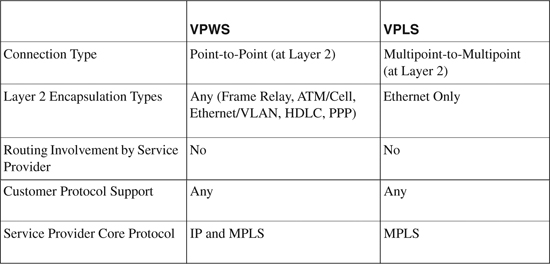
The information in Table 19-4 is compiled from the Cisco Networkers session presentation# AGG-1001 – “Introduction to Layer 2 Transport and Tunneling Technologies (L2VPNS).”
Note
IETF L2VPN is a working group responsible for standardization of Layer 2 VPN architectures, such as VPLS and VPWS. More details can be found at http://www.ietf.org/html.charters/l2vpn-charter.html.
Implementing L2VPN
There are a number of variations in L2VPN designs and deployments, and several different technologies are available that can be used depending on different Layer 2 services. The technologies include Ethernet VLAN, Frame Relay PVC, ATM VC, HDLC, and PPP transport over a packet-based infrastructure across a service provider IP/MPLS cloud. The following sections provide some basic examples of Layer 2 service implementations, i.e., Ethernet VLAN over MPLS using VPWS- and VPLS-based architecture.
Implementing Ethernet VLAN over MPLS Service—Using VPWS Based Architecture
Figure 19-8 topology demonstrates basic VPWS (Virtual Private Wire Service) L2VPN point-to-point scenario transporting Ethernet VLAN over MPLS.
As shown in Figure 19-8, the MPLS core interconnects customer Ethernet between two sites over the MPLS core. The customer CE router on each site is configured on the same Layer 3 subnet 192.168.100.0/24, thereby establishing a virtual Layer 2 (VLAN) connection over the MPLS core network.
Figure 19-8. Implementing Ethernet VLAN over MPLS – Basic VPWS-L2VPN
Implementing Ethernet VLAN over MPLS Service—Using VPLS-Based Architecture
Figure 19-9 topology demonstrates a basic VPLS (Virtual Private LAN Service) L2VPN scenario transporting Ethernet VLAN over MPLS.
The MPLS core interconnects customer Ethernet VLAN between two sites, thereby establishing a virtual Layer 2 (VLAN) connection over the MPLS core network.
Figure 19-9. Implementing Ethernet VLAN over MPLS—Basic VPLS-L2VPN
Summary
In addition to connectivity services, service providers are continually struggling to increase service offerings and differentiated end-to-end IP services with cutting edge technologies. This fast-shifting economical growth is heavily dependent on their ability to deliver managed network services along with traditional connectivity services.
Multiprotocol Label Switching (MPLS) is a widely used core transport technology that is used to carry Layer 2 and Layer 3 services that transport over a packet-switched network (PSN).
MPLS VPN is a key service solution that provides end-to-end QoS, enabling efficient utilization of existing networks to build highly efficient, scalable, next-generation networks.
This chapter provided a basic overview of the MPLS architecture and briefly explained how it works, as well as a comparison on MPLS VPN and IPsec VPN solutions and deployment scenarios.
The chapter focused mainly on MPLS VPN architecture and the two basic types of trusted VPN deployments. The chapter covered details on Cisco Layer 2 VPN (L2VPN) and Layer 3 VPN (L3VPN) solution architecture and provided basic deployment and implementation guidelines.
References
http://www.cisco.com/en/US/netsol/ns590/networking_solutions_white_paper09186a008009d67f.shtml
http://www.cisco.com/en/US/netsol/ns589/networking_solutions_sub_sub_solution.html
http://www.cisco.com/en/US/products/ps6604/products_ios_protocol_group_home.html
http://www.cisco.com/en/US/netsol/ns588/networking_solutions_sub_sub_solution.html
http://www.cisco.com/en/US/products/ps6603/products_ios_protocol_group_home.html
http://www.cisco.com/en/US/netsol/ns585/networking_solutions_white_paper0900aecd801edd5f.shtml
http://www.cisco.com/en/US/products/ps6648/products_ios_protocol_option_home.html
http://www.cisco.com/en/US/products/ps6603/products_white_paper09186a00801ed506.shtml
http://www.rfc-editor.org/rfc/rfc4364.txt
http://www.vpnc.org/vpn-technologies.html
http://www.cisco.com/univercd/cc/td/doc/product/software/ios124/124cg/hmp_c/part20/mpbbk4.htm
http://www.cisco.com/en/US/tech/tk436/tk428/technologies_configuration_example09186a0080093fcc.shtml
http://www.cisco.com/en/US/tech/tk436/tk428/technologies_configuration_example09186a00800a6c11.shtml
http://www.cisco.com/en/US/tech/tk436/tk428/tech_configuration_examples_list.html