Chapter 22. Anomaly Detection and Mitigation
Denial-of-service (DoS) attacks and distributed denial-of-service (DDoS) attacks have become more sophisticated and prevalent over the years and are therefore major issues in service provider and large-scale network deployments.
In today’s rapidly evolving networks, attackers are often one step ahead. Effective mitigation of DDoS attacks is a pressing problem. Proactive detection and prevention mechanisms can help protect the network from these malicious cloaking techniques.
The Cisco Anomaly Detection and Mitigation solution provides a self-defending preventive solution for detecting and mitigating complex and sophisticated DoS and DDoS attacks.
This chapter provides the details of the Anomaly Detection and Mitigation solution that uses the industry standard Cisco Traffic Anomaly Detectors and Cisco Guard DDoS Mitigation devices. The chapter takes a closer look at core concepts, solution architecture, solution components, and how all these are combined to demonstrate how the solution works through various illustrations and diagrams.
The chapter provides a brief overview of the configuring and managing of the Cisco Traffic Anomaly Detector and Cisco Guard Mitigation devices, showing sample configurations that use a command-line interface (CLI) and defining how to configure Zones, Filters, Policies, Learning Process parameters, and how to activate the Anomaly Detection and the Guard system.
Attack Landscape
The main objective of any DoS and DDoS attacks is to prevent authorized users from accessing network resources.
Denial-of-Service (DoS) Attack Defined
The main objective of a DoS-type attack is to prevent access to authorized users by consuming the resources such as bandwidth, memory, storage, and CPU. The attacker floods the target host(s) with unwanted packets and uses up all the resources, thus crippling the network and saturating network links, resulting in regular traffic either being slowed down, disrupted for some period, or completely interrupted.
Typically, a DoS attack is an attempt to disrupt services and prevent legitimate users from accessing certain information or services. For example, a DoS attack can be launched to prevent legitimate users from accessing e-mail, browsing Internet websites, printing services, or preventing access to any local network resources. Examples of DoS attacks include but are not limited to
• Resource removal
• Resource modification
• Resource saturation
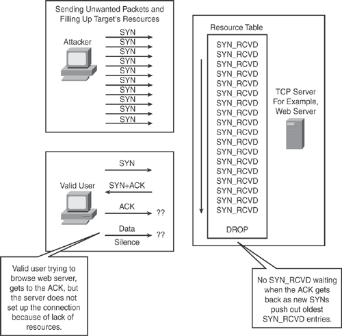
Figure 22-1 illustrates a basic form of DoS attack showing resource saturation in which an attacker is sending a large number of unwanted TCP SYN packets, thereby filling up the target server resources, thus preventing legitimate users from establishing a valid TCP connection.
Figure 22-1. DoS Attack Defined—How It Works
Distributed Denial-of-Service (DDoS) Attack—Defined
The objective of DDoS is similar to DoS; the major difference is that the attacker does not directly launch the attack to the target. In DDoS, the attacker compromises a multitude of systems by exploiting the security vulnerabilities and weaknesses within the systems and infects those systems with a resident Trojan, so that the attacker can take control of all compromised systems remotely.
After the compromised hosts are infected with a Trojan and ready for the attacker to use, the attacker uses them as a launch pad by sending huge amounts of unwanted traffic to the target host, thus creating a DDoS effect. This type of attack is called “distributed” because the attacker is using multiple hosts to launch the DoS attack on a single host or multiple host systems.
In DDoS, the attacker hides behind the compromised hosts, and the target victim is blindfolded so it cannot recognize the real perpetrator.
Victims of a DDoS attack consist of both the end targeted system and all systems maliciously used and controlled by the attacker in the distributed attack.
DDoS type attacks are harder to track down than DoS attacks, and they challenge defense mechanisms.
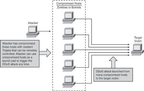
Figure 22-2 illustrates a basic form of DDoS attack in which an attacker has compromised multiple hosts with resident Trojans, thereby allowing the hosts to be remotely controlled. The attacker can use compromised hosts as a launch pad to trigger the DDoS attack to the target victims, thus preventing legitimate users from establishing connections.
Anomaly Detection and Mitigation Systems
Anomaly-based intrusion detection and mitigation is an enhanced solution that combats DoS and DDoS attacks as previously discussed.
Anomaly detection solutions provide intelligence-based intrusion prevention by monitoring system activity and categorizing the traffic as either normal or anomalous. The classification is based on heuristics or rules, rather than patterns or signatures.
Figure 22-2. DDoS Attack Defined —How It Works
Anomaly detection systems are initially in learning mode so that they can characterize normal activity and establish a baseline for normal traffic. Anomaly detection involves defining or learning normal activity and looking for deviations from various baseline profiles. Examples include the following:
• Protocol anomaly: Involves looking for deviations from a standard protocol and is useful for identifying deviations from normal protocol behavior.
• Network anomaly: Involves watching or learning the normal traffic levels—for example, using a time-based classification of normal traffic activity. If deviation from normal traffic activity is detected, an alarm is generated. This technique is prone to false alarms but can be combined with other techniques to improve accuracy.
• Behavioral anomaly: Involves learning normal user behavior and detecting the relational traffic pattern activities of individual hosts or a group of hosts. If a change occurs, an alarm is generated. This technique is most useful in a very tightly controlled environment because behavior changes occur frequently in a network.
After these baselines are established, anomaly detection compares all traffic with the baseline profile, and any deviation from the profile is considered as potential attack traffic.
On many occasions and with increasing frequency, legitimate traffic is integrated with the attack traffic. Therefore, traffic patterns must be closely examined in near real-time so that the valid traffic can still be passed without interruption. Attack traffic can then be diverted to a mitigation device where scrubbing is performed to eliminate bad traffic and allow legitimate traffic to flow seamlessly.
Anomaly detection and mitigation algorithms can detect all kinds of attacks, including day-zero attacks. This is different from signature-based systems, which can only detect attacks for which a static signature has been defined.
An anomaly detection technique has the following characteristics:
• Is signatureless; it does not require use of patterns or signatures.
• Is granular, based on observed traffic pattern behavior.
• Can perform relational- and behavioral-based anomaly detection.
• Detects in real-time; anything reported is actually happening.
• Supports dynamic filtering.
• Includes sophisticated antispoofing techniques.
• Can detect day-zero and minute-zero attacks.
• Can highlight behaviors that are not indicative of attack traffic, but are still of interest.
• Includes traffic diversion architecture allowing flexibility in topological placement.
Cisco DDoS Anomaly Detection and Mitigation Solution
Cisco offers state-of-the-art solutions to protect against DDoS attacks by using the industry standard Cisco Anomaly Detection and Mitigation products.
The Cisco Anomaly Detection and Mitigation solution combats complex and sophisticated DDoS attacks. This solution can be used for service provider and enterprise environments. Some of the features are the following:
• Detect and mitigate a wide range of DDoS attacks.
• Classify legitimate traffic and attack traffic in real-time.
• Block the attack traffic by using source-based dynamic filters.
• Block large botnets and zombie attacks.
• Deliver multigigabit performance at line rate for detection and mitigation.
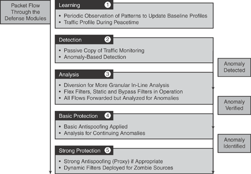
Figure 22-3 illustrates the packet flow through the defense modules that provides advanced DDoS protection using the Cisco Anomaly Detection and Mitigation solution.
Figure 22-3. Advanced DDoS Protection Using the Cisco Anomaly Detection and Mitigation Solution
The Cisco DDoS Anomaly Detection and Mitigation solution consists of two basic deployment components:
• Cisco Traffic Anomaly Detector
• Cisco Guard DDoS Mitigation
Note
Both products are available as appliance-based solutions and integrated service modules for Cisco Catalyst 6500 Series Switches and Cisco 7600 Series Routers.
Cisco Traffic Anomaly Detector
The Cisco Traffic Anomaly Detector is the industry’s standard solution for detecting the most complex and sophisticated DDoS attacks. The Cisco Traffic Anomaly Detector works in combination with the Cisco Guard DDoS Mitigation device.
Cisco Traffic Anomaly Detectors identify potential DDoS attacks and divert traffic destined for the targeted device to the Cisco Guard to scrub, identify, and block malicious traffic in real-time, without affecting the flow of legitimate traffic.
Cisco Traffic Anomaly Detection is based on sophisticated anomaly detection intelligence capabilities that compare current activity to profiles of known normal behavior, enabling the Traffic Anomaly Detector to identify any type of DDoS attacks including day-zero attacks. The detector has a built-in behavioral recognition engine that enables traffic pattern comparison, thus eliminating the need to manually update profiles. This also reduces the number of false alarms, in contrast to signature-based engines.
The Cisco Traffic Anomaly Detectors deliver high performance detection, diversion, and alerting capabilities for potential DDoS attacks, worms, and day-zero attacks. Without impacting legitimate flow, the Traffic Anomaly Detector triggers a mitigation service to remove malicious attack flows and blocks the attack before network resource availability is adversely affected.
The Cisco Traffic Anomaly Detector can monitor attack flows at full multigigabit line rates, by identifying more than 100,000 sources per device in a single attack, thereby providing robust protection for high-volume environments.
The Cisco Traffic Anomaly Detector is based on a unique, patented Multi-Verification Process (MVP) architecture developed by Cisco, as shown in Figure 22-5. MVP utilizes the latest behavioral analysis and attack recognition technology to proactively detect and identify all types of DDoS attacks.
Cisco Traffic Anomaly Detector products are available in two options:
• Cisco Traffic Anomaly Detector XT 5600 Series Appliance
• Cisco Traffic Anomaly Detector Module for Cisco Catalyst 6500 Series Switches and Cisco 7600 Series Routers
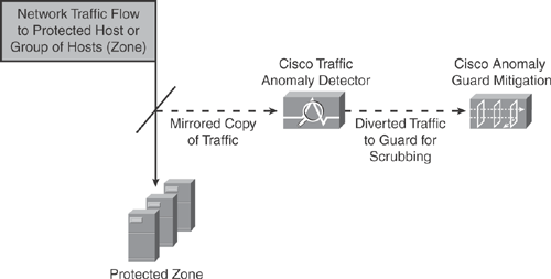
Cisco Traffic Anomaly Detector continuously monitors a mirrored copy of selected traffic destined for a protected host or group of hosts and compiles detailed profiles that indicate how individual hosts behave under normal operating conditions. When a traffic pattern deviation is detected, it is considered as the anomalous behavior of a potential attack, and the Detector responds based on user-configured preferences by
• Sending an operator alert to initiate a manual response
• Triggering an existing management system
• Launching the Cisco Guard XT DDoS Mitigation Appliance to immediately begin mitigation services
The Traffic Anomaly Detector performs the following tasks:
• Traffic learning: Classifies and categorizes the normal zone traffic pattern by using an algorithm-based process to establish a baseline. During the learning process, the Detector modifies the default zone traffic policies and policy thresholds to match the characteristics of normal zone traffic. The traffic policies and thresholds define the reference points that the Detector uses to determine when the zone traffic is normal or abnormal (indicating an attack on the zone).
• Traffic anomaly detection: Detects anomalies in protected zone traffic based on normal traffic characteristics.
Figure 22-4 illustrates the operation of the Cisco Traffic Anomaly Detector in which the Traffic Detector receives a mirrored copy (using SPAN/VACL) of the network traffic for analysis. If deviation is detected, it reroutes the traffic to the Cisco Guard Mitigation for analysis and mitigation services.
Figure 22-4. Cisco Traffic Anomaly Detection and Mitigation Operation
The Traffic Detector can operate as an independent DDoS detection and alarm component; however, it works optimally with the Cisco Guard to provide mitigation services completing the DDoS protection solution.
Cisco Traffic Detector device is capable of processing attack traffic at multigigabit line rates, and the recognition engine identifies the broadest range of DDoS attacks, including
• TCP-based attacks
• UDP-based attacks
• HTTP attacks
• DNS attacks
• Botnets and Zombie attacks
To provide the best possible implementation scenario, the Cisco Traffic Anomaly Detector can be deployed downstream, close to protected resources in the data center, or upstream adjacent to a Cisco Guard to provide more widespread coverage.
Combined with the Cisco Guard Mitigation, the Cisco Traffic Anomaly Detector provides industry’s most comprehensive DDoS defense system.
Cisco Guard DDoS Mitigation
Cisco Guard DDoS Mitigation is the industry’s standard solution for defeating the most complex and sophisticated DDoS attacks. Cisco Guard DDoS Mitigation works in combination with the Cisco Traffic Anomaly Detector device.
The Cisco Guard Mitigation delivers multigigabit performance to protect the service provider and large-scale enterprise environments from DDoS attacks by performing granular per-flow-level analysis and identification, and it provides blocking capabilities to stop DDoS attack traffic in real-time while allowing legitimate traffic to flow seamlessly. The guard is capable of filtering attacks from hundreds of thousands of zombies simultaneously.
Cisco Guard DDoS Mitigation products are available in two options:
• Cisco Guard DDoS Mitigation XT 5600 Series Appliance
• Cisco Guard DDoS Mitigation Guard Module for Cisco Catalyst 6500 Series Switches and Cisco 7600 Series Routers
One of the most important advantages of Cisco Guard is that it is not an inline solution. It can therefore be deployed off the critical path at any point in the network, yet achieve the in-the-traffic flow between the data stream type of scenario by using its dynamic diversion capability. This also ensures that the failure of a Cisco Guard device does not impact the traffic flow.
As shown in Figure 22-4, the Cisco Guard device receives diverted suspect traffic from the Cisco Traffic Anomaly Detector for data scrubbing and cleaning services, using its advanced statistical profiling techniques and antispoofing technologies. During the traffic-cleaning process, the Cisco Guard identifies and drops the attack packets and forwards the legitimate packets to their targeted network destinations.
The Cisco Guard is based on a unique Multi-Verification Process (MVP) architecture developed by Cisco. The diverted traffic is subjected to the MVP architecture that employs the most advanced anomaly recognition, protocol analysis, source verification, and antispoofing technologies.
Cisco Guard provides robust protection against all types of attacks with the integrated dynamic filters and active verification technologies, driven by a sophisticated profile-based anomaly recognition engine. In addition, the protocol analysis and rate limiting features ensure that only valid traffic gets through without overwhelming other downstream devices.
Figure 22-5 illustrates the innovative MVP architecture that delivers multiple interactive layers of defense, which are designed to identify and block the specific packets and flows responsible for the attack.
Figure 22-5. Multiverification Process (MVP) Architecture
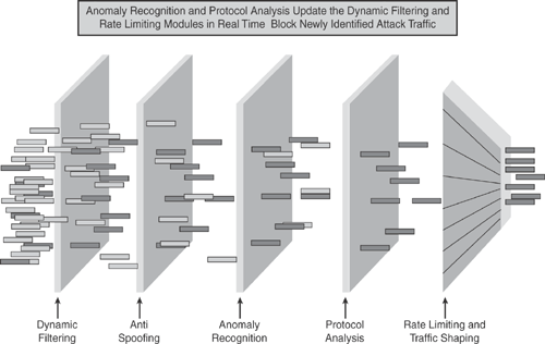
The information in Figure 22-5 is compiled from the Cisco Networkers session presentation BRKSEC-2030 on “Deploying Network IPS.”
The Cisco Guard Mitigation device is capable of processing attack traffic at multigigabit line rates, and the recognition engine identifies a broad range of DDoS attacks, including
• TCP-based attacks
• UDP-based attacks
• HTTP attacks
• DNS attacks
• SIP (VoIP) attacks
• Botnets and Zombie attacks
The Guard DDoS Mitigation performs the following tasks:
• Traffic learning: Classify and categorize the normal zone traffic pattern using an algorithm-based process to establish a baseline. During the learning process, the Guard modifies the default zone traffic policies and policy thresholds to match the characteristics of normal zone traffic. The traffic policies and thresholds define the reference points that the Guard uses to determine when the zone traffic is normal or abnormal (indicating an attack on the zone).
• Traffic protection: Distinguish between legitimate and malicious traffic and filter the malicious traffic so that only the legitimate traffic is allowed to pass on to the protected zone.
• Traffic diversion: Divert the zone traffic from its normal network path to the Guard learning and protection processes and then return the legitimate zone traffic to the network.
To provide the best possible implementation scenario, the Cisco Guard can be deployed in a distributed upstream configuration at the backbone level, close to the network edge or ISP connection.
Cisco Guard is typically deployed off the critical path at any point in the network, from enterprise access points to peering points off an ISP backbone.
Combined with the Cisco Traffic Anomaly Detector, the Cisco Guard Mitigation provides the industry’s most comprehensive DDoS defense system.
Putting It All Together for Operation
As mentioned earlier, the Cisco Traffic Anomaly Detector device works in combination with the Cisco Guard Mitigation device to provide a comprehensive anomaly protection against DDoS attacks.
Figures 22-6 through 22-10 illustrate the combination of the Cisco DDoS solution and the dynamic diversion solution.
The following steps highlight each step of the anomaly detection and mitigation process during an attack life cycle in reference to Figures 22-6 through 22-10.
Note
It is assumed that the Traffic Anomaly Detector and the Guard Mitigation device have both completed the learning process, classifying and categorizing the normal zone traffic pattern using an algorithm-based process to establish a baseline.
Step 1. As illustrated in Figure 22-6, the Traffic Anomaly Detector device is deployed closer to the protected zone to detect anomalies and provide detection and alerting capabilities. Normal traffic flow is moving to Zone1 and Zone2 servers. The Traffic Anomaly Detector device identifies an anomaly in Zone2 and has detected an intrusion that deviates from the normal traffic policy.
Step 2. As illustrated in Figure 22-7, the Traffic Anomaly Detector device alerts the Cisco Guard Mitigation device to begin dynamic diversion, which redirects traffic destined for the targeted resources, and provides traffic flow information of the intrusion detected. This can either be triggered manually or automatically.
Step 3. As illustrated in Figure 22-8, the Cisco Guard Mitigation device triggers a redirection to the edge router for the target victim’s traffic under suspicion to be redirected to the Guard. This can be achieved via routing protocol and Border Gateway Protocol (BGP) updates. All other traffic continues to flow directly to its designated destinations without interruption. Only the target victim traffic is redirected to the Guard.
Step 4. As illustrated in Figure 22-9, the edge router is now diverting all target victims’ traffic (only) to the Cisco Guard Mitigation device for scrubbing. The diverted traffic is then scrutinized to classify and separate bad flows from legitimate flows filtering malicious data. The Guard performs detailed flow-level analysis to identify and mitigate the attack.
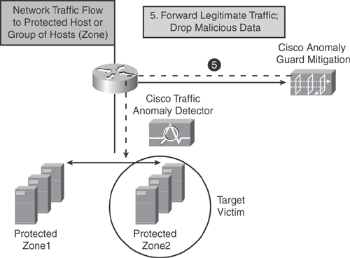
Step 5. As illustrated in Figure 22-10, the Guard filters and blocks all malicious attack traffic and forwards all legitimate traffic to its designated destination, ensuring uninterrupted network flow for valid users and legitimate transactions.
Figure 22-6. Step 1—Anomaly Is Detected by the Cisco Traffic Detector in a Protected Zone
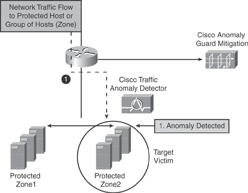
Figure 22-7. Step 2—Cisco Traffic Detector Alerts Cisco Guard
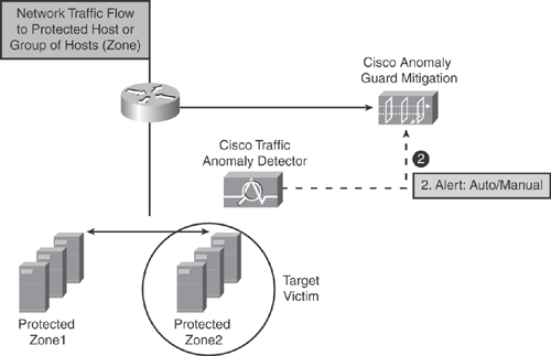
Figure 22-8. Step 3—Cisco Guard Triggers Traffic Diversion
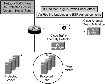
Figure 22-9. Step 4 —Diverted Traffic Is Redirected to Cisco Guard for Scrubbing
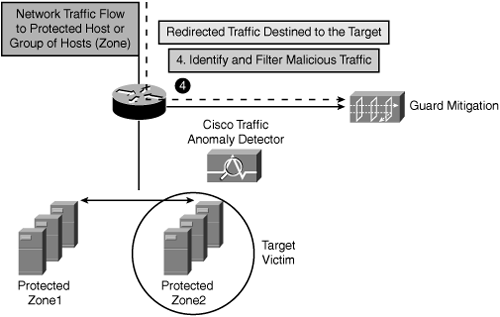
Figure 22-10. Step 5 —Cisco Guard Forwards Legitimate Traffic to Original Destination
The information concept in Figures 22-6 to 22-10 is compiled from the Cisco Networkers session presentation BRKSEC-2030 on “Deploying Network IPS.”
Configuring and Managing the Cisco Traffic Anomaly Detector
The following sections briefly outline the configuration parameters for the Cisco Traffic Anomaly Detector device.
Similar to the IPS sensor appliance, the Anomaly Detector can be configured by using the command-line interface (CLI) and the built-in GUI WBM user interface.
The Detector needs to be initialized using CLI for basic parameters such as the IP address, gateway, routes, and access control list (ACL). After the Detector is initialized and routable in the network, it can be accessed using the web-based GUI to configure the remaining tasks.
Several command modes on the Detector CLI are available for user access, and the access is mapped according to various CLI privilege levels, similar to the IPS Sensor software. By default, the user admin account is available with full administrative access rights to the Detector CLI.
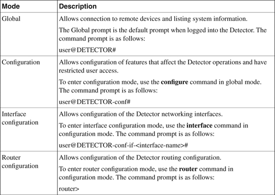
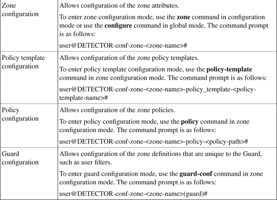
Table 22-1 provides details of the various command and configuration modes used in the Detector CLI.
Table 22-1. Detector Command Configuration Modes
Managing the Detector
As mentioned earlier, the Detector needs to be initialized using the CLI Console access.
However, the Detector can be accessed and managed using one of the following methods:
• CLI Console access (for bootstrapping initial parameters)
• Secure Shell (SSH) session
• Built-in Web-Based Management (WBM) application
• Cisco DDoS Multi-Device Manager (MDM)
Initializing the Detector Through CLI Console Access
By default, the Detector does not have a configuration and requires basic initial parameters enabled for management via the GUI application. When the Detector boot process finishes, use the CLI console to log in to the CLI Console through the default username admin and password rhadmin.
Note
The Detector has four physical interfaces: eth0, eth1, giga0, and giga1. The out-of-band interfaces are eth0 and eth1 (10/100/1000 Ethernet sockets for out-of-band management). The eth0 or eth1 must be configured with an IP address and subnet mask. The in-band interfaces (copper or fiber socket) are giga0 and giga1.
Example 22-1 shows basic initial configuration parameters in the configuration mode that are used to activate the out-of-band management interface, assign the default gateway, and enable the built-in web-based GUI service for management (WBM).
By default, the Detector has restricted access and protects access for connections to the Detector, and any user trying to access the Detector must be explicitly permitted within the ACL. Example 22-1 shows a host located at IP address 10.1.1.150, which is being permitted in the ACL, so that it can manage the Detector by using the built-in WBM application and shows how to enable the MDM.
Example 22-1. Basic Detector Initialization Parameters Using CLI Console
user@DETECTOR-conf# interface eth1
user@DETECTOR-conf-if-eth1# ip address 192.168.1.1 255.255.255.0
user@DETECTOR-conf-if-eth1# no shutdown
user@DETECTOR-conf# default-gateway 192.168.1.254
user@DETECTOR-conf# service wbm
user@DETECTOR-conf# permit wbm 10.1.1.150
user@DETECTOR-conf# service mdm
user@DETECTOR-conf# mdm server 10.1.1.150
In addition to the previous sample configuration, other basic parameters can be configured optionally:
• Configuring Hostname, Date, and Time
• Configuring various integrated services (for example, Routing, Network Time Protocol (NTP), Simple Network Management Protocol (SNMP), WBM, MDM, and SSH)
• Configuring Access Control using AAA
• Configuring TACACS+ parameters and attributes
• Configuring keys for SSH, SSH FTP (SFTP), and SCP connections
• Configuring NTP parameters
• Configuring SNMP parameters
• Configuring Communication parameters to establish a secure session with the Guard using SSL or SSH
After configuring basic initial parameters using CLI is completed, the Detector can be managed via the standard web browser from the desktop PC (Internet Explorer) by entering the following address:
Note
The Detector also supports TACACS+ authentication for user authentication. If configured, the Detector uses the TACACS+ user database for user authentication instead of its local database.
Configuring the Detector (Zones, Filters, Policies, and Learning Process)
After initializing the Detector as shown in previous section, several other parameters need to be configured on the Detector to complete the configuration, such as Zones, Zone Filters, and Policies. These can either be configured using the CLI Console or are best implemented using the built-in web-based GUI manager application.
The following section highlights some of the basic concepts for configuring Zones, Zone Filters, Policies, and the Detector Learning phase, and for activating anomaly detection and the Guard device:
• Configuring zones: A zone is a network element that the Detector monitors for DDoS attacks. A zone can be any combination of a server, client, or router, or a subnet, or an entire network. The zone is a group of protected devices that are monitored. The Detector monitors the devices in a zone, and if an attack is identified, the Guard is activated to protect the zone. The Detector can simultaneously monitor traffic for several zones provided that their network address does not overlap. There are two ways to create a new zone: first, using one of the system-defined zone templates that allow creation of a new zone with the default policies and filters of the template; and second, duplicating an existing zone. After a zone has been created, additional zone attributes need to be configured, such as the zone IP address range.
• Configuring zone filters: After a zone is defined, zone filters need to be applied to enable the analysis detection level for the zone traffic flow. Zone filters also define the way the Detector handles specific traffic flows. Zone filters enable the Detector to analyze zone traffic for anomalies and bypass the Detector anomaly detection features. Zone filters can be customized for different methods that the Detector uses to detect traffic anomalies. There are several types of zone filters, such as Dynamic filters, Bypass filters, and Flex-content filters. Each of these is used for analyzing specific traffic flows and applying the required protection level to the specified traffic flow on the Detector. For example, the dynamic filter is created when the Detector identifies anomalies in the zone traffic and activates the Guard device to protect the zone. Zone filter parameters can be modified as per user requirements. Figure 22-11 illustrates the Detector zone filter system.
Figure 22-11. Detector Zone Filter System
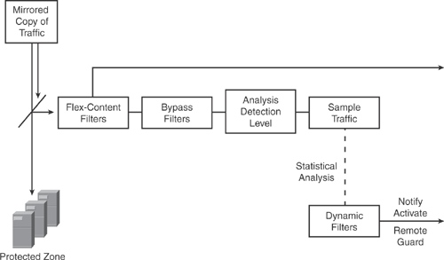
Note
The information in Figure 22-11 is compiled from Cisco product configuration guide on “Cisco Traffic Anomaly Detector Configuration Guide (Software Version 6.0)” at http://www.cisco.com/en/US/docs/security/anomaly_detection_mitigation/appliances/detector/v6.0/configuration/guide/conffilt.html.
• Configuring policies: Each zone contains a set of policies that are used to perform statistical analysis of the zone traffic flow and enforce the policy. The Detector uses predefined policy templates to construct the policies for each zone. A policy template is a collection of policy construction rules that the Detector uses during the policy construction phase to create the zone policies. Several default policy templates are available for use. Here are three examples: First, the ip_scan policy template is used to detect scans when a client from a specific source IP address tries to access many destination IP addresses in the zone. Second, the tcp_services template is used for TCP services on ports other than those that are HTTP related, such as ports 80 and 8080. Third, the tcp_ratio template is used for monitoring ratios between different types of TCP packets. For example, the ratio of SYN packets to FIN/RST packets and several other policy templates are available. Zone policy parameters can be modified after they are created. Policy triggers and the action also need to be configured to define the action that the policy takes when it is activated. The Detector also includes additional policy templates for zones designed for specific types of attacks or specific services—for example to monitor TCP-based WORM attacks.
• Detector learning process and policy construction phase: As mentioned previously, the Detector is initially in the learning process to establish the normal zone traffic patterns and threshold conditions to establish a baseline for the zone. The Detector creates the zone policies and its thresholds during this learning phase based on the normal traffic patterns. To activate the policy construction phase for zones, use the learning policy-construction command from the global configuration. For example, the learning policy-construction * command initiates the learning process for all zones when the asterisk (*) character is used. Alternatively, individual zones can also be named to initiate the learning phase separately. Similarly, use the learning threshold-tuning command from the global configuration mode to initiate the threshold tuning phase. After the learning is completed, accept the results from the policy construction phase for the respective zones using the learning accept command.
• Activating zone anomaly detection: Finally, to activate zone anomaly detection, issue the following command in the zone configuration mode.
detect [learning]
The learning keyword is optional and enables the Detector to detect anomalies in the zone traffic and tune the zone policy thresholds by using detect and learn functions, as mentioned previously in the detector learning process section. Note that to enable the learning process, the switch must be configured with the port mirroring feature.
• Activating the guard to protect a zone: As discussed previously, the Detector monitors the zone continuously for anomalies. When the Detector detects a zone traffic anomaly, it creates dynamic filters that can activate the Guards that are associated with the Detector. There are several ways to configure the Detector to activate a remote Guard: for example, the first way is to use a remote Guard list that uses SSL to enable remote activation and zone synchronization; the second way is to use SSH to enable remote activation only; the third way is to use BGP to send a BGP route update to inform the adjacent router to divert the target zone traffic to the remote Guard. The Detector can also be configured as offline to issue a notification when an attack on the zone occurs or enable manual activation to create dynamic filters to activate remote Guards.
• Synchronizing zone configurations: The zone synchronization process allows you to create copies of zone configuration on both the Detector and the Guard. The synchronization process can be used to create, configure, and modify a zone on the Detector and then update the same zone information to the Guard. There are two modes of synchronization: the Detector to Guard Synchronization, where the Detector copies the zone configuration from itself to the Guard, and the Guard to Detector Synchronization, where the Detector copies the zone configuration from the Guard to itself.
As discussed previously, several parameters need to be configured to complete the Cisco Traffic Anomaly Detector deployment (refer to Table 22-1).
These entire configurations can either be done via the CLI Console access or the built-in GUI WBM application.
For complete details on configuring various options, refer to the following Cisco technical documentation.
Tip
Refer to the following Cisco documentation for further details to configure the Cisco Traffic Anomaly Detector:
http://www.cisco.com/en/US/products/ps5887/products_configuration_guide_book09186a00807bfb20.html
http://www.cisco.com/en/US/products/ps5887/products_configuration_guide_book09186a00805e01e4.html
Configuring and Managing Cisco Guard Mitigation
This section briefly outlines the configuration parameters for the Cisco Guard Mitigation device.
Similar to the Detector software, the Guard Mitigation device can be configured by using the command-line interface (CLI) and also the built-in GUI WBM user interface.
The Guard needs to be initialized using CLI for basic parameters such as the IP address, gateway, routes, and ACL. After the Guard is initialized and routable in the network, it can be accessed using the web-based GUI to configure the remaining tasks.
Several command modes on the Guard CLI are available for user access. The access is mapped according to various CLI privilege levels, in a manner that is similar to the Detector software. By default, the user admin account is available with full administrative access rights to the Guard CLI.
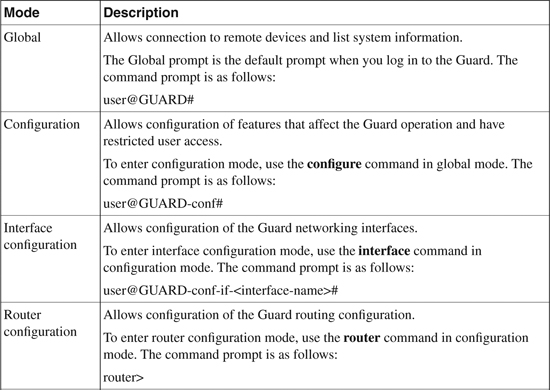
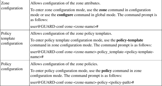
Table 22-2 provides details of the various command and configuration modes used in the Guard CLI.
Table 22-2. Guard Command Configuration Modes
Managing the Guard
As mentioned earlier, the Guard needs to be initialized by using the CLI Console access.
However, the Guard can be accessed and managed using one of the following methods:
• CLI Console access (for bootstrapping initial parameters)
• Secure Shell (SSH) session
• Built-in WBM application
• Cisco DDoS MDM
Initializing the Guard Using the CLI Console Access
After the Guard boot process finishes, use the CLI console to log in to the CLI Console, using the default username admin and password rhadmin.
Note
The Guard has four physical interfaces: eth0, eth1, giga0, and giga1. The out-of-band interfaces are eth0 and eth1 (10/100/1000 Ethernet sockets for out-of-band management). The eth0 or eth1 must be configured with an IP address and subnet mask. The in-band interfaces (copper or fiber socket) are giga0 and giga1.
Example 22-2 shows basic initial configuration parameters in the configuration mode that are used to activate the out-of-band management interface, assign the default gateway, and enable the built-in web-based GUI service for management (WBM).
By default, the Guard has restricted access and protects access for connections to the Guard, and any user trying to access the Guard must be explicitly permitted within the ACL. Example 22-2 shows a host located at IP address 10.1.1.150 that is being permitted in the ACL so that it can manage the Guard by using the built-in web-based GUI manager (WBM) application.
Example 22-2. Basic Guard Initialization Parameters Using CLI Console
user@GUARD-conf# interface eth1
user@GUARD-conf-if-eth1# ip address 192.168.10.1 255.255.255.0
user@GUARD-conf-if-eth1# no shutdown
user@GUARD-conf# default-gateway 192.168.10.254
user@GUARD-conf# service wbm
user@GUARD-conf# permit wbm 10.1.1.150
In addition to the previous sample configuration, other basic parameters can also be configured optionally:
• Hostname, Date, and Time
• Various integrated services (Routing, NTP, SNMP, WBM, and SSH)
• Access Control using AAA
• TACACS+ parameters and attributes
• Keys for SSH, SFTP, and SCP connections
• NTP parameters
• SNMP parameters
• Communication parameters to establish a secure session with the Detector using SSL or SSH
After the configuration of basic initial parameters using CLI is completed, the Guard can be managed via the standard web browser from the desktop PC (Internet Explorer) by entering the following address:
Note
The Guard also supports TACACS+ authentication for user authentication. If configured, the Guard uses the TACACS+ user database for user authentication instead of its local database.
Configuring the Guard (Zones, Filters, Policies, Learning Process)
After initializing the Guard as shown in the previous section, several other parameters need to be configured on the Guard to complete the configuration, such as zones, zone filters, and policies. These can either be configured using the CLI Console or are best implemented using the built-in web-based GUI manager application.
The following section highlights some of the basic concepts of configuring Zones, Zone Filters, Policies, Guard Learning phase, and activating anomaly detection and the Guard device.
• Configuring zones: A zone is a network element that the Guard monitors for DDoS attacks. A zone can be any combination of a server, client, router, subnet, or an entire network. The zone is a group of protected devices, which are monitored. The Guard monitors the devices in a zone, and if an attack is identified, the Guard is activated to protect the zone. The Guard can simultaneously monitor traffic for several zones provided that their network addresses do not overlap. There are three ways to create a new zone on the Guard: by using one of the predefined zone templates that allow creation of a new zone with the default policies and filters of the template; by duplicating an existing zone; or by copying a zone configuration from the Detector. After a zone has been created, additional zone attributes need to be configured, such as a zone IP address range.
• Configuring zone filters: After a zone is defined, zone filters need to be applied to enable the analysis detection level for the zone traffic flow. Zone filters also define the way the Detector handles specific traffic flows. Zone filters enable the Guard to analyze zone traffic for anomalies and apply the basic or strong level of protection to separate legitimate traffic from malicious traffic, drop malicious packets, and forward traffic directly to the zone, bypassing the Guard protection features. Zone filters can be customized for different methods that the Guard uses to detect traffic anomalies. There are several types of zone filters, including User filters, Dynamic filters, Bypass filters, and Flex-content filters. Each of these types is used for analyzing specific traffic flows and applying the required protection level to the specified traffic flow on the Guard. For example, the dynamic filter is created when the Guard identifies anomalies in the zone to protect the zone. Similarly, User filters apply the required protection level to the specified traffic flow. Most important, the User filters are the first to be enforced as an action occurs when the Guard identifies abnormal or malicious traffic. Zone filter parameters can be modified as per user requirements. Figure 22-12 illustrates the Guard Zone filter system.
Figure 22-12. Guard Zone Filter System
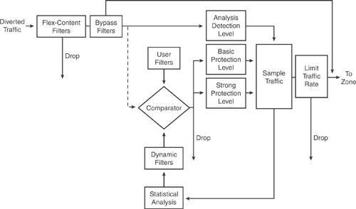
Note
The information in Figure 22-12 is compiled from Cisco product configuration guide on “Cisco Guard Configuration Guide (Software Version 6.0)” at http://www.cisco.com/en/US/docs/security/anomaly_detection_mitigation/appliances/guard/v6.0/configuration/guide/conffilt.html.
• Configuring policies: Each zone contains a set of policies that is used to perform statistical analysis of the zone traffic flow and enforce the policy. The Detector uses predefined policy templates to construct the policies for each zone. A policy template is a collection of policy construction rules that the Detector uses during the policy construction phase to create the zone policies. Several default policy templates are available for use, such as an ip_scan policy template for detecting scans when a client from a specific source IP address tries to access many destination IP addresses in the zone. Another example is the tcp_services template, which is used for TCP services on ports other than those that are HTTP-related, such as ports 80 and 8080. A final example is the tcp_ratio template, which is used for monitoring ratios between different types of TCP packets, such as the ratio of SYN packets to FIN/RST packets and several other policy templates. Zone policy parameters can be modified after being created. Policy triggers and the action also need to be configured to define the action that the policy takes when it is activated. The Guard also includes additional policy templates for zones designed for specific types of attacks or specific services—for example, to monitor VoIP applications.
• Understanding Guard protection levels: As shown in Figure 22-12, the Guard applies three protection levels during the zone filter system process, in which it applies different processes to the traffic flow. Three protection levels exist in the Guard: the Analysis protection level, which allows the traffic to flow monitored, but uninterrupted, during zone protection, as long as no anomalies are detected; the Basic protection level that activates antispoofing and antizombie functions to authenticate the traffic by inspecting the suspicious traffic flow to verify its source; and the most powerful strong protection level, which activates severe antispoofing functions that inspect the traffic flow packets to verify the flow legitimacy. After applying a protection function to the zone, the Guard continuously monitors the traffic for anomalies if it detects an anomaly in traffic destined to the zone, it applies a stronger protection level.
Note
Protection levels have a static configuration and cannot be configured manually.
• Guard learning process and policy construction phase: As mentioned previously, the Guard is initially in the learning process to establish the normal zone traffic patterns and threshold conditions to establish a baseline for the zone. The Guard creates the zone policies and its thresholds during this learning phase based on the normal traffic patterns. For the Guard to learn the zone traffic characteristics, traffic needs to be diverted from its normal network path to the Guard. As the Guard analyzes the traffic, it injects the traffic back into the network. Note that before initiating the learning process, traffic diversion must be set up correctly. Traffic diversion can be configured using a routing protocol on the Guard. To activate the policy construction phase for zones, use the learning policy-construction command from the global configuration. For example, the learning policy-construction * command initiates the learning process for all zones when the asterisk (*)character is used. Alternatively, individual zones can be named to initiate the learning phase separately. Similarly, use the learning threshold-tuning command from the global configuration mode to initiate the threshold tuning phase. After the learning is done, accept the results from the policy construction phase for the respective zones using the learning accept command.
• Activating zone protection: The Guard can be configured to activate zone protection when it receives a message from the Detector; alternatively, zone protection can be manually triggered on the Guard for a zone under attack. To activate the Guard for zone protection, issue the following command in the zone configuration mode.
protect [learning]
The learning keyword is optional and enables the Guard to detect anomalies in the zone traffic and tune the zone policy thresholds using the protect and learn function.
• Synchronizing zone configurations: The zone synchronization process allows the creation of copies of the zone configuration on both the Detector and the Guard. The synchronization process can be used to create, configure, and modify a zone on the Detector, and then update the same zone information to the Guard. There are two modes of synchronization: the Detector to Guard Synchronization, in which the Detector copies the zone configuration from itself to the Guard, and the Guard to Detector Synchronization, in which the Detector copies the zone configuration from the Guard to itself.
As discussed previously, several parameters need to be configured to complete the Cisco Guard Mitigation deployment (refer to Table 22-2).
These entire configurations can be accomplished either via the CLI Console access or the built-in GUI WBM application.
For a complete detail of configuring various options, refer to the Cisco technical documentation.
Tip
Refer to the following Cisco documentation for further details to configure the Cisco Traffic Anomaly Detector:
http://www.cisco.com/en/US/products/ps5888/products_configuration_guide_book09186a00807bfb1e.html
http://www.cisco.com/en/US/products/ps5888/products_configuration_guide_book09186a00805e01c8.html
Summary
In today’s rapidly growing networks, dynamically evolving threats are on the rise. Complex DoS attacks and DDoS attacks equipped with the sophisticated intelligence are clogging the networks to immobilize traffic flow, resulting in severe network degradation and meltdown.
DDoS attacks have increased over the years and are becoming a major threat to be combated. Service providers and large-scale network deployments are struggling to find comprehensive solutions to mitigate DDoS attacks.
At the same time, the trend has also shifted and evolved from reactive detection to a more proactive detection and prevention approach that uses anomaly-based and behavioral-based systems.
The Cisco Anomaly Detection and Mitigation solution is the answer to these concerns, providing a self-defending preventive solution to detect and mitigate complex and sophisticated DoS and DDoS attacks and day-zero attacks.
The chapter gave details of the Cisco Anomaly Detection and Mitigation solution and provided core concepts of the anomaly architecture and how it works with the aid of various illustrations and diagrams.
The chapter provided a brief overview of configuring and managing the Cisco Traffic Anomaly Detector and Cisco Guard Mitigation devices through use of various sample configurations.
The chapter described and explained the important aspects of configuring Zones, Filters, Policies, and Learning Process parameters, as well as how to activate the Anomaly Detection and the Guard system.
References
http://www.cisco.com/en/US/products/ps5879/Products_Sub_Category_Home.html
http://www.cisco.com/go/detector
http://www.cisco.com/en/US/products/ps6236/index.html
http://www.cisco.com/en/US/products/ps5888/products_data_sheet0900aecd8055d170.html
http://www.cisco.com/en/US/products/hw/modules/ps2706/products_data_sheet0900aecd80220a6e.html
http://www.cisco.com/en/US/products/ps6235/index.html
http://www.cisco.com/en/US/products/ps5888/products_data_sheets_list.html
http://www.cisco.com/en/US/products/ps5887/products_configuration_guide_book09186a00807bfb20.html
http://www.cisco.com/en/US/products/ps5888/products_configuration_guide_book09186a00807bfb1e.html