
Configuring Router Dial Peers
Introduction
At this point in the Quick Reference Sheets, you have seen how to configure voice ports on Cisco voice-enabled routers. However, you have not yet trained the routers to reach specific destinations. That is the focus of this section. Specifically, you are going to create dial peers that inform the routers how to reach specific phone numbers. Consider the following topology.
Routers R1 and R2 each have a plain old telephone service (POTS) dial peer that points to their locally attached phone and a VoIP dial peer that points to the IP address of the remote router.
Therefore, when extension 1111 dials extension 2222, router R1 searches for a dial peer that matches a destination pattern of 2222. In this case, R1 has a VoIP dial peer that points to R2’s IP address of 10.1.1.2. R1 then forwards the call to R2. Then, R2 receives the incoming call that is destined for extension 2222. R2 searches for a dial peer that matches a destination of 2222, and it finds a POTS dial peer that specifies FXS port 1/1/1. The FXS port then sends ringing voltage out port 1/1/1. Extension 2222 goes off-hook, and the end-to-end call is complete.
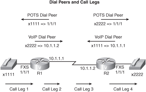
Notice that you have a total of four dial peers that allow a call in the opposite direction. Also, notice that four stages of the call (that is, “call legs”) are defined, two call legs from the perspective of each router, as follows:
• Call Leg #1—The call comes in to R1 on FXS port 1/1/1.
• Call Leg #2—The call is sent from R1 to IP address 10.1.1.2.
• Call Leg #3—R2 receives an incoming call that is destined for extension 2222.
• Call Leg #4—R2 forwards the call out FXS port 1/1/1.
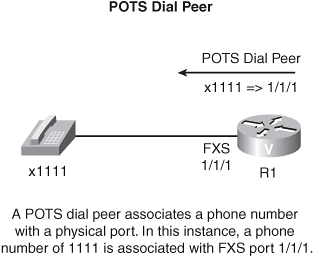
POTS Dial Peers
When configuring a POTS dial peer, specify the following two parameters:
• The destination-pattern (that is, the phone number)
• The physical port address
Consider the following POTS dial-peer configuration.
R1(config)#dial-peer voice 1111 pots
R1(config-dial-peer)#destination-pattern 1111
R1(config-dial-peer)#port 1/1/1
In this example, an analog phone is attached to FXS port 1/1/1. You entered dial-peer configuration mode for a POTS dial peer with the dial-peer voice 1111 pots command. Notice that the 1111 in the dial-peer command does not need to match the phone number. The number is merely a locally significant tag. However, to make the configuration more intuitive to interpret, you might want to adopt a practice of using the extension number as the dial-peer tag. The phone’s extension number of 1111 is specified with the destination-pattern 1111 command. The phone’s physical location is specified with the port 1/1/1 command.
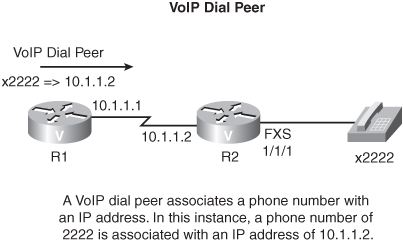
VoIP Dial Peers
When configuring a VoIP dial peer, you specify a remote phone number with the same destination-pattern command that was used in a POTS dial peer. However, instead of identifying a local port, a VoIP dial peer specifies the voice packets’ destination IP address. Consider the following VoIP dial-peer configuration:
R1(config)#dial-peer voice 2222 voip
R1(config-dial-peer)#destination-pattern 2222
R1(config-dial-peer)#session target ipv4:10.1.1.2
In this example, router R1 is sending voice packets that are destined for extension 2222 across the IP WAN to IP address 10.1.1.2, as specified with the session target command. Note that you must prepend ipv4: to the IP address.
At this point, you understand how to establish a dial plan for two phones that are separated by an IP WAN. However, what if you had 1000 extensions on the other side of the WAN? You certainly would not want to create 1000 dial peers. Fortunately, the Cisco IOS allows you to use wildcards to specify a range of addresses. A few of the more frequently used wildcards are as follows:
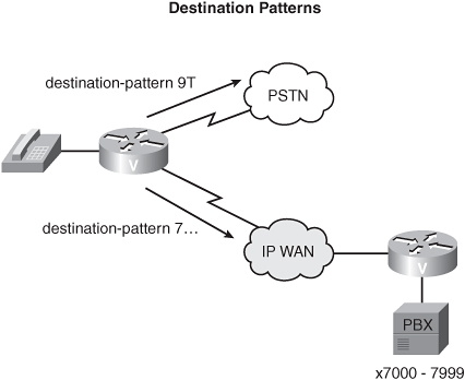
• T—A T represents a dial string of any length. For example, you could specify a destination pattern of 9T to match any number that begins with a 9, and then you could point any calls matching that pattern out to the PSTN. Because the T can be any number of digits, the router forwards the call, by default, after no digits have been dialed for 10 seconds (by default) or after the caller presses the # key.
• .—A period indicates any single digit. For example, you could specify extension numbers in the range 7000–7999 with the 7... destination pattern.
• []—Brackets can specify a range of numbers. For example, a 123[4-6] destination pattern identifies a four-digit number of 1234, 1235, or 1236.
At this point, you have learned about using the destination-pattern and port commands to match dial peers.
However, a couple of additional options exist for matching inbound dial peers, incoming called-number and answer-address. To illustrate, consider that all calls destined for a call center are sent out the same trunk, but when the calls reach the call center, they might need to go to different locations (for example, to different customer service agents). You can configure this type of behavior with the incoming called-number command.
You can use the answer-address command instead of the destination-pattern command. For example, if you operate a call center that supports international customers, you can use the answer-address number command to match a calling number, using caller ID information, to direct the call to an appropriate customer service agent.
You can have a configuration in which multiple destination patterns match a dialed number. The logical question is “Which destination pattern do you use?” The “most specific” destination pattern is used when multiple destination patterns match a called number. Consider the following configuration:
Router(config)#dial-peer voice 1 voip
Router(config-dial-peer)#destination-pattern 2468
Router(config-dial-peer)#session target ipv4:192.168.1.1
Router(config-dial-peer)#dial-peer voice 2 voip
Router(config-dial-peer)#destination-pattern 2...
Router(config-dial-peer)#session target ipv4:192.168.2.2
Router(config)#dial-peer voice 3 voip
Router(config-dial-peer)#destination-pattern 2T
Router(config-dial-peer)#session target ipv4:192.168.3.3
In this configuration, a dialed number of 2468 is matched by all three dial peers. However, dial peer 1 is the most specific dial peer, matching the pattern exactly without the use of wildcards used to forward the call.
You might want to have multiple dial peers that match specific numbers, for redundancy reasons. For example, you might want to send calls that are destined for extension 4444 across the IP WAN. However, if the WAN is not available, you want to place the call through the PSTN. To accomplish this, you can have two dial peers: a VoIP dial peer that points across the IP WAN and a POTS dial peer that points to a physical port attached to a PBX or the PSTN. You then can indicate that you prefer to use the VoIP dial peer by assigning “preference” values to the dial peers with the preference number command.
For example, in dial-peer configuration mode for the VoIP dial peer, you could enter the preference 0 command. Similarly, you could use the preference 1 command for the POTS dial peer. Because lower preference values are preferred, the VoIP dial peer is used, if it is available. If the VoIP dial peer is not available, the call would fail over to the POTS dial peer. Note that the valid range of preference values is 0-10.
Digit Forwarding
When the router is connected to a PBX or the PSTN, you need to understand how the router forwards digits. By default, digits that are matched explicitly by the destination-pattern command in a POTS dial peer are not forwarded. For example, consider a destination pattern of 123...., which matches the dialed digits 1235555. By default, the router forwards the digits 5555 only to the attached equipment, because explicitly matched digits are stripped. To prevent this behavior, you can use the no digit-strip command in dial-peer configuration mode.
In addition to forwarding dialed digits, you also might want to forward additional digits. For example, you might want to prepend a dialed number with a 9 before forwarding the number to a PBX. You can prepend digits to a dialed number with the prefix number command.
As opposed to using the no digit-strip command, you can specify exactly how many digits to forward by using the forward-digits number command. For example, you could use the dial-peer configuration-mode command forward-digits 5 to forward the five right-most digits in the dialed number.
You can even instruct the router to replace one dialed number with another. For example, you might have a telecommuter whose home phone number is 555-1234. However, all employees at the headquarters location have four-digit extension numbers. To make the telecommuter’s phone appear as a local extension, you can use the num-exp dialed_number translated_number command. In this example, if you wanted to represent the telecommuter’s home phone with a four-digit extension number of 2020, you could enter the num-exp 2020 5551234 command in global-configuration mode.
Connection Types
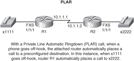
Recall the operation of a PLAR connection, as described in a previous section, “Introduction.” A PLAR connection automatically dials a predetermined number when a phone goes off-hook. In the following example, when extension 1111 goes off-hook, router R1 automatically dials extension 2222.
R1(config)#dial-peer voice 2222 voip
R1(config-dial-peer)#destination-pattern 2222
R1(config-dial-peer)#session target ipv4:10.1.1.2
R1(config-dial-peer)#voice-port 1/1/1
R1(config-voiceport)#connection plar 2222
PLAR Off-Premise Extension (PLAR-OPX) is similar to PLAR. However, with PLAR-OPX, instead of a router answering an incoming call from a PBX—in which case the PBX would consider the call complete—the call is not answered until the destination phone goes off-hook. As a result, an unanswered call can be rerouted to voice mail by the PBX.
In the following PLAR-OPX example, when extension 1111 dials extension 2222, the PBX forwards the call to router R1. Router R1 then places a call to extension 2222. However, because of the PLAR-OPX configuration, R1 (and therefore the PBX) does not consider the call complete until extension 2222 goes off-hook.

Router(config)#dial-peer voice 2222 voip
Router(config-dial-peer)#destination-pattern 2222
Router(config-dial-peer)#session target ipv4:10.1.1.2
Router(config-dial-peer)#voice-port 1/1/1
Router(config-voiceport)#connection plar-opx 2222
Dial Plans
Dial plans organize a group of phone numbers in a hierarchical fashion. Consider the North American dialing plan, which consists of ten digits, as follows:
859-555-1212
The first three digits (that is, 859) indicate an area code, which is typically associated with a geographical location within North America. The following three digits (that is, 555) are the central office code (that is, the NXX code), which identifies a central office location within the area that is specified by the area code. The final four digits (that is, 1212) point the local central office to a specific local loop that goes out to a subscriber’s physical location.
When designing a dial plan for a customer, consider the following items:
• Where is the dial plan logic located (for example, in a gateway [GW] or in a CCM)?
• Will digit translation be required?
• Can the numbers in the dial plan be reached by multiple paths, for fault-tolerant purposes?
• Should you use digit translations to give dial plans a consistent feel?
• Does an attached voice-mail system require a different number of digits than an extension?
• When do area codes need to be dialed?
• How can the dial plan support different countries, which can have country codes of varying lengths?