
Ensuring Voice Quality
Introduction
In this section, you examine several quality of service (QoS) tools to help you preserve voice quality as voice packets traverse voice-enabled networks. Specifically, you make the following distinctions that affect voice quality:
• Selecting codecs
• Minimizing delay
• Provisioning sufficient bandwidth
• Overcoming jitter
However, you first learn to measure voice quality.
Challenges to Voice Quality
As mentioned earlier in these Quick Reference Sheets, voice quality can be impacted when voice packets are dropped or delayed. Also, variation in the delay (that is, jitter) affects the listener’s perception of the voice quality. The fidelity of a signal is a measure of the frequency range that is represented by a signal. However, in the voice environment, your main concern is transporting the majority of the frequencies that make up speech patterns, rather than reproducing high-fidelity music, as you would on a home stereo system. Therefore, the G.711 codec samples frequencies up to 4000 Hz, which contains more than 90 percent of the frequencies that are used in human speech patterns.
Earlier, you learned how to measure voice quality using mean opinion score (MOS) or Perceptual Speech Quality Measurement (PSQM). The choice of codecs impacts the score that is given to the voice quality. For example, the G.711 codec has an MOS of 4.1, whereas G.729 has an MOS of 3.92.
Another approach to measuring voice quality is Perceptual Evaluation of Speech Quality (PESQ). Like PSQM, PESQ uses test equipment to measure voice quality, as opposed to a “trained ear.” However, PESQ attempts to match MOS rankings. For example, if a codec had an MOS of 3.92, it should have a PESQ score of 3.92. However, the maximum value on the PESQ scale is 4.5, whereas the MOS scale reaches 5.0.
Overcoming Delay
Voice is sent over IP networks in RTP packets, which use UDP for transport. Because UDP is connectionless, the network does not attempt to retransmit a lost packet. Also, because IP networks can load-balance traffic across multiple links, packets can arrive with various interpacket intervals. These characteristics can lead to variable delay, which is called jitter. Another example of variable delay is queuing delay, which your queuing strategy can introduce. A queuing strategy determines the order that packets are transmitted out of a queue in the presence of congestion.

Fortunately, the Cisco voice-enabled routers have a “jitter buffer,” which stores packets as they come into a router and then plays the packets out in a smooth fashion. When packets are in the jitter buffer, you can reorder them based on RTP sequence numbers. Although the IOS determines the size of the jitter buffer is automatically, if jitter problems are not eliminated, you can manually configure the jitter buffer with the playout-delay mode command. Specifically, the dial-peer configuration-mode command playout-delay mode adaptive along with the playout-delay maximum size command can specify, in milliseconds, the maximum size of the jitter buffer, while allowing the jitter buffer to dynamically adjust its size based on network conditions. Alternatively, you can use the playout-delay mode fixed and the playout-delay nominal size dial-peer configuration-mode commands to specify statically the size of the jitter buffer. You can view current jitter conditions with the show call active voice command.
Some delay components, however, are fixed, meaning they do not change during a call. The following are examples of fixed delay:
• Coder delay—The amount of time required for a codec to process a voice packet. (For example, a G.729 codec can require 2.5 to 10 ms to do the coding, depending on how many voice calls a DSP is coding. Similarly, the G.723 codec requires 5 to 20 ms for coding.)
• Serialization delay—The amount of time required for a packet to exit a serial interface. (For example, a 1500-byte frame requires 214 ms to exit a serial interface running at 56 kbps.)
• Propagation delay—The amount of time required for a packet to travel across the network.
Although serialization delay is considered a fixed delay, for the duration of a call, you can minimize the effect of serialization delay by performing Link Fragmentation and Interleaving (LFI). LFI fragments large data payloads and interleaves smaller voice packets among the fragments. On a Voice over IP over PPP circuit, the LFI mechanism that you use is multilink PPP (MLP). However, on a Voice over IP over Frame Relay (VoIPovFR) network, your LFI tool of choice is FRF.12.
The combined fixed and variable delay components create the delay budget for a design. However, too much delay adversely affects voice quality. As a design guideline, the ITU G.114 recommendation states that the one-way delay for a voice packet should not exceed 150 ms.
LAN Quality of Service
Normally, quality of service (QoS) technologies are related to the WAN. However, the LAN also needs QoS. For example, you might have multiple Fast Ethernet devices simultaneously communicating to a server that is also connected through Fast Ethernet. Such a situation could lead to “oversubscription” of the bandwidth. Therefore, frames that cannot be sent at the moment can be buffered by a Catalyst switch in a queue. If the queue overflows, all incoming packets are discarded, even high-priority voice packets.
However, if you place voice frames in a different queue from lower-priority data frames, even if the data queue overflows, the voice queue still accepts incoming voice frames.
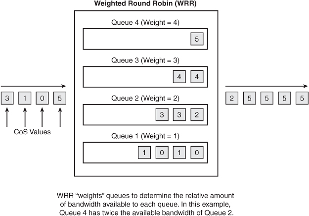
After frames are queued, the switch’s queuing strategy determines in what order frames are emptied from the queues and how bandwidth is made available to those queues. Specifically, many Cisco Catalyst switches support Weighted Round Robin (WRR) queuing, which specifies the “weight” that is given to each queue.
As an example, consider that queue 1 has a weight of 1 and that queue 4 has a weight of 4. In this example, queue 4 receives four times the bandwidth of queue 1 because of its weight.
Catalyst switches such as the 2950 and the 3550 offer four queues where you can place frames. Other switch models can have a different number of queues. However, Cisco recommends a 2Q1T approach, which specifies that you are using two queues, where each of the queues has one threshold. Having a single threshold causes a queue to delay discarding frames until the queue fills to capacity.
WAN Quality of Service
Two broad categories of QoS tools exist: Integrated Services (IntServ) and Differentiated Services (DiffServ). Integrated Services provides QoS by guaranteeing treatment to a particular traffic flow. A commonly used IntServ tool is the Resource Reservation Protocol (RSVP).
As the name suggests, Differentiated Services differentiates among different types of traffic and provides different levels of service based on those distinctions. Instead of forcing every network device to classify traffic, DiffServ can mark packets with a particular priority marking that other network devices can reference.
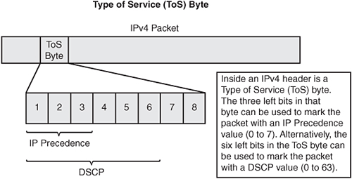
A common type of packet marking is Differentiated Services Code Point (DSCP). DSCP uses the 6 left-most bits in an IPv4 header’s type of service (ToS) byte. With 6 bits at its disposal, up to 64 DSCP values (0 to 63) can be assigned to various classes of traffic.
Another type of marking that uses the IPv4 ToS byte is IP Precedence, which uses the 3 left-most bits in the ToS byte. Because it uses 3 bits, IP Precedence has values in the range 0 to 7. However, Cisco recommends that IP Precedence values of 6 or 7 never be used, because they are reserved for network and Internet use. Just marking a packet does not change its operation, unless QoS tools are enabled that can reference that marking. Fortunately, multiple QoS tools exist that can make decisions based on these markings.
You can place most QoS tools in one of the following areas:
• Classification and marking
• Congestion avoidance
• Congestion management
• Traffic conditioning
• Signaling
• Link efficiency mechanisms
Classification and Marking
When configuring QoS, decide which devices in the network you “trust” to make markings. These devices should be as close to the source as possible. For example, you can select a Cisco IP phone as the trust boundary.
When you decide on a trust boundary, configure your edge devices to classify traffic into classes. For example, you could have a Voice over IP (VoIP) class, a database class, an FTP class, a video class, and a default class.
When the traffic is categorized into traffic classes, mark the various traffic classes with DSCP markings. This prevents other devices in the network from having to reclassify the traffic. Instead, these other devices can reference the DSCP markings. However, as mentioned earlier, marking by itself does not alter the behavior of traffic.
Congestion Avoidance
The purpose of congestion avoidance is to prevent an interface’s output queue from filling to capacity, because if a queue is full, all newly arriving packets are discarded. Some of those packets can be high priority, and some can be low priority. However, if the queue is full, no room exists for a packet.
With a congestion-avoidance tool, drop thresholds are defined for various markings (for example, DSCP markings). Therefore, as a queue begins to fill, lower-priority packets are dropped more aggressively than higher-priority packets, thus preventing the queue from ever filling to capacity. The Cisco congestion-avoidance tool of choice is Weighted Random Early Detection (WRED).

Congestion Management
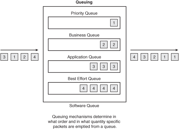
Congestion-management tools are queuing tools. These queuing tools decide how packets are placed in an interface’s output queues and how the packets are forwarded out of the queues. Several queuing tools are available in the IOS. However, modern queuing approaches include the following:
• Low Latency Queuing (LLQ)—The preferred queuing method for voice and video traffic, where traffic can be classified in up to 64 different classes, with different amounts of bandwidth given to each class. This method includes the ability to give priority treatment to one or more classes.
• Class-Based Weighted Fair Queuing (CB-WFQ)—Similar to LLQ, with the exception of having no priority-queuing mechanism.
Many of the Cisco QoS mechanisms are configured using a three-step configuration process called Modular QoS CLI (MQC).

Following is an MQC example where you are classifying various types of e-mail traffic (for example, SMTP, IMAP, and POP3) into one class-map. The KaZaa protocol, which is frequently used for music downloads, is placed in another class-map. Voice over IP (VoIP) traffic is placed in yet another class-map. Then, the policy-map assigns bandwidth allocations or limitations to these traffic types. The code is as follows:
Router(config)#class-map match-any EMAIL
Router(config-cmap)#match protocol pop3
Router(config-cmap)#match protocol imap
Router(config-cmap)#match protocol smtp
Router(config-cmap)#exit
Router(config)#class-map MUSIC
Router(config-cmap)#match protocol kazaa2
Router(config-cmap)#exit
Router(config)#class-map VOICE
Router(config-cmap)#match protocol rtp
Router(config-cmap)#exit
Router(config)#policy-map CVOICE
Router(config-pmap)#class EMAIL
Router(config-pmap-c)#bandwidth 128
Router(config-pmap-c)#exit
Router(config-pmap)#class MUSIC
Router(config-pmap-c)#police 32000
Router(config-pmap-c)#exit
Router(config-pmap)#class-map VOICE
Router(config-pmap-c)#priority 256
Router(config-pmap-c)#exit
Router(config-pmap)#exit
Router(config)#interface serial 0/1
Router(config-if)#service-policy output CVOICE
Notice that the CVOICE policy-map makes 128 kbps of bandwidth available to e-mail traffic. However, KaZaa version 2 traffic has its bandwidth limited to 32 kbps. Voice packets not only have access to 256 kbps of bandwidth, but they also receive “priority” treatment, meaning that they are sent first (that is, ahead of other traffic), up to the 256-kbps limit.
The next logical question is this: What happens to all the traffic that you did not classify? Interestingly, Cisco created a class-map named class-default, which categorizes any traffic that is not matched by one of the defined class-maps. Finally, in the previous example, the policy-map is applied in the outbound direction on the Serial 0/1 interface.
Traffic Conditioning
Although some of the congestion-management techniques can guarantee bandwidth amounts, in some situations, you might want to limit bandwidth usage. For example, you might want to prevent oversubscription of a link. The two categories of traffic conditioning are as follows:
• Policing—Limits traffic rates, with excess traffic being dropped
• Shaping—Limits traffic rates, with excess traffic being delayed
Shaping buffers excess traffic, while policing drops excess traffic. These characteristics suggest that policing is more appropriate on high-speed interfaces, whereas shaping is more appropriate on low-speed interfaces.

Signaling
The IntServ model uses signaling to allow an application to reserve bandwidth for the duration of the application. RSVP is the primary QoS signaling protocol. One of the main characteristics of signaling is that signaling is performed end to end, meaning that all routers along the path from the source to the destination must be configured to support the IntServ mechanism (for example, RSVP). Also, note that when the Cisco voice-enabled routers are configured to reserve bandwidth using RSVP, reservations are made in both directions.
Link Efficiency Mechanisms
Link efficiency mechanisms help make the most of the limited bandwidth that is available on WAN links. Two link efficiency mechanisms are as follows:
• Link Fragmentation and Interleaving (LFI)—Takes large payloads, fragments them, and interleaves smaller packets among the fragments to reduce serialization delay for latency-sensitive traffic (for use on link speeds of less than 768 kbps)
• RTP Header Compression (cRTP)—Takes a 40-byte VoIP header and compresses it to 2 or 4 bytes (for use on link speeds of less than 2 Mbps)

AutoQoS
Optimizing a QoS configuration for VoIP can be a daunting task. Fortunately, Cisco added a feature called AutoQoS to many of its router and switch platforms. AutoQos automatically generates router-based or switch-based VoIP QoS configurations.
On a router platform, the following command enables AutoQoS from either interface-configuration mode or from DLCI-configuration mode, if you have a Frame Relay circuit:
Router(config-if)#auto qos voip
After you enter this command, the IOS automatically executes a series of QoS configuration commands that depend on the configured interface bandwidth. For example, on a PPP interface running at less than 768 kbps, the AutoQoS feature automatically configures LLQ, cRTP, MLP, and even an SNMP configuration, where quality issues can be reported to an SNMP network management server.
Preventing WAN Oversubscription
Consider a scenario in which you have 50 kbps of bandwidth on an IP WAN, and perhaps a single voice call requires 25 kbps of bandwidth. After two voice calls are placed across the IP WAN, no more bandwidth is available. Therefore, if a third phone call is set up across the IP WAN, you have oversubscribed the bandwidth; this leads to poor quality for all three calls. To prevent such an occurrence, you can configure one or more Call Admission Control (CAC) mechanisms to prevent this oversubscription. CAC mechanisms fall in one of the following three categories:
• Local CAC mechanisms—Make admission-control decisions based on information known to the local router (for example, the number of connections placed using a particular dial peer).
• Measurement-based CAC mechanisms—Send Service Assurance Agent (SAA) probes out into the network to determine network conditions. A request to place a phone call across the IP WAN is then permitted or denied based on the probes’ results.
• Resource-based CAC mechanisms—Determine how much bandwidth has been used between different network locations. For example, a gatekeeper can keep track of the amount of bandwidth that is used between two defined zones.
Cisco also supports CAC features for the following call control protocols, which were discussed earlier:
• H.323—CAC can permit or deny a call attempt based on a router’s available resources (for example, CPU and memory).
• SIP—CAC can send SAA probes into the network to determine whether a call attempt should be permitted.
• MGCP—CAC can make admission-control decisions based on available router resources, SAA probes, and available network bandwidth.
Bandwidth Provisioning
The essence of bandwidth provisioning for voice networks is to determine how many calls that you might need to support during peak periods. You can obtain current call volumes from various sources, such as your telephony service provider or your PBX’s Station Message Detail Recorder (SMDR) records.
As a designer, you must determine an acceptable grade of service (GoS), which is the probability that a call will be blocked because of bandwidth oversubscription. Typically, you use a GoS of P(.01), which specifies a 1 percent probability of a blocked call during the busiest hour.
With the GoS determined, you next need to determine the number of Erlangs that you need to support during your busiest hour. An Erlang is defined as 1 hour of conversation. For example, two phone calls that lasted 30 minutes each would equal one Erlang.
As a design best practice, you can calculate the number of Erlangs that you need to support with the following formula:
Erlangs = Hours_of_phone_use_in_a_month / 22 * 0.15 * 1.10
The 22 represents the number of business days per month. The 0.15 indicates that approximately 15 percent of your phone system usage occurs during the busiest hour. Finally, the 1.10 adds 10 percent for call-processing overhead.
With the number of required Erlangs and the GoS value, you can determine the number of required trunks using an Erlang table or calculator, such as the one found at http://www.erlang.com/calculator/erlb.
When you have the number of trunks that you need, you can translate that number into the amount of bandwidth that you require by determining how much bandwidth is needed for a single voice call and then multiplying that amount by the number of trunks that you need. As a reminder, you can use the Cisco voice bandwidth calculator for this purpose. You can find this calculator at http://tools.cisco.com/Support/VBC/do/CodecCalc1.do.
Note that a Cisco.com login is required for the bandwidth calculator.