Overview of Legacy and IP Telephony Networks
Introduction
Understanding emerging Voice over IP (VoIP) technologies requires a solid understanding of legacy telephony networks. Therefore, the Quick Reference Sheets in this section review many of the terms and concepts that surround legacy and packet telephony networks, and those technologies are then contrasted with IP Telephony technologies.
Legacy Telephony Networks
The Public Switched Telephone Network (PSTN) is at the heart of the legacy telephony network. PSTN components include the following items:
• Edge devices (for example, phones) are used by customers to interface with the PSTN.
• Local loops connect customer locations to a local central office (CO) over a pair of wires called tip and ring.
• Phone switches allow one phone to connect to another phone by dialing a phone number. The switch interprets the dialed digits and interconnects the dialing phone’s local loop with the destination phone’s local loop. The “phone company” has switches that are located in COs. However, companies can have their own phone switches [for example, Private Branch Exchanges (PBXs) or key systems] located locally.
• Trunks interconnect phone switches.
Companies that have their own phone switches can select between PBXs or key systems. PBXs are typically more scalable than key systems, supporting 20 to 20,000 phones. PBX users in the United States typically dial a 9 to access an outside line. However, key systems traditionally have buttons on a key phone that the user presses to access a specific outside line. For example, you might have been in a store and heard an intercom announcement such as, “Kevin, pick up line 2.” In that example, Kevin would go to a “key phone” and press the line 2 button to access the call. Because of their scalability limitations, key systems typically support a maximum of 30 to 40 users.
Call signaling makes it possible to place an end-to-end voice call. Consider the following steps that are used to establish an end-to-end voice call:
1. A phone goes off-hook and sends digits to the local phone switch.
2. The local phone switch examines the dialed digits, makes a forwarding decision, and sends signaling information to the destination phone switch.
3. The destination phone switch signals the destination phone by sending ringing voltage to the phone.
When a user dials digits on an analog phone, those digits can be communicated to the local phone switch using either dual-tone multifrequency (DTMF) or pulse dialing. DTMF sends tones that are composed of two frequencies, whereas pulse dialing rapidly opens and closes the local loop to indicate dialed digits.
With digital circuits, such as T1s or E1s, multiple conversations can be carried in different channels on the same circuit. Each of these digital channels needs bits for signaling information. Common approaches include the following:
• Common channel signaling (CCS)—Has a channel that is dedicated to signaling. For example, in an Integrated Services Digital Network (ISDN) circuit, the D channel is dedicated to signaling.
• Channel associated signaling (CAS)—Can use framing bits from a few of the channels to serve as signaling bits. Sometimes this is called robbed-bit signaling.
Analog circuits have their own signaling mechanisms, such as the following:
• Loop-start—Causes a phone switch to seize a line when loop current is flowing
• Ground-start—Causes a phone switch to seize a line after the phone temporarily grounds the “ring” side of the circuit
• E&M wink start—Seizes a line when the polarity on an E&M circuit is reversed and then quickly flipped back to the original polarity
Digital circuits can use multiplexing techniques to place multiple conversations on a single link. For example, time-division multiplexing can give a “time slice” to a specific channel, and by “taking turns,” you can send 24 conversations across a single link.
Frequency-division multiplexing (FDM) allows multiple conversations to be sent at the same time using different frequencies. For example, dense-wavelength-division multiplexing (DWDM) simultaneously sends multiple light frequencies over a fiber-optic cable.
Packet Telephony Networks
Many companies that have PBXs at more than one site and interconnect those PBXs through the PSTN are migrating to a packet telephony network. A packet telephony network allows companies to preserve their existing investment in PBX technologies, while eliminating the recurring expense for the trunks that interconnect their PBXs. Specifically, companies can connect their PBXs to routers that are already interconnected through a wide-area network (WAN). The PBXs can then send their signaling information and voice calls over the WAN.
Call-forwarding intelligence can reside in the routers. For increased scalability, however, you can configure routers to point to external call agents. Such a topology lays the foundation for other packet telephony technologies, including the following:
• IP phones have an Ethernet connection that sends and receives voice calls.
• Call agents replace much of the functionality that was provided previously by the PBX. For example, a call agent can be configured with route plans that dictate how voice calls are forwarded. The Cisco CallManager (CCM) is an example of a call agent.
• Gateways can forward calls between different types of networks. For example, a call from an IP phone could be forwarded through a gateway to the PSTN.
• Gatekeepers keep track of WAN resources and, based on available resources, either permit or deny a request to place a call across the WAN. In addition, the gatekeeper can provide E.164 number resolution.
• Multipoint Control Units (MCUs) contain digital signal processor (DSP) resources and can support the mixing of audio streams in a conference call.
Simply placing a voice call across a WAN does not guarantee the quality of the voice call. Data applications, for example, tend to be more forgiving of dropped or delayed packets than applications such as voice or video. Therefore, the quality of service (QoS) technology is an integral part of Cisco VoIP designs, and an entire section in these Quick Reference Sheets focuses on QoS technologies.
IP Telephony Networks
Although packet telephony is more of a generic term, covering Voice over IP (VoIP), Voice over Frame Relay (VoFR), and Voice over ATM (VoATM), the primary focus of these Quick Reference Sheets is creating IP-based telephony networks using VoIP technologies. Therefore, with the foundational understanding of legacy and packet telephony networks, you delve into some of the components of IP Telephony. First, you consider the analog interfaces that are available on voice-enabled routers.
A Foreign Exchange Station (FXS) port allows you to connect plain old telephone service (POTS) devices to a router. For example, you could attach a traditional analog phone, speakerphone, or fax machine to an FXS port on a Cisco router, and that FXS port can act like a PBX or CO switch. For example, an FXS port can provide a dial tone when the phone goes off-hook, interpret dialed digits, and send ringing voltage to the attached phone.
A Foreign Exchange Office (FXO) port connects to a phone switch (for example, a PBX or the PSTN). The FXO port can connect into the traditional tip-and-ring connection that comes from a CO or a PBX. Because it is acting as a phone, an FXO port can go off-hook, dial digits, and answer incoming calls.
E&M is the third type of analog port, and this port interconnects PBXs. The “E” and “M” originally referred to “earth” and “magneto,” although you can think of “ear” and “mouth” to better visualize the receive and transmit functions of E&M.

Two primary digital ports (that is, interfaces) are the T1 and E1 interfaces. A T1 interface can send 24 voice channels using channel associated signaling (CAS). Alternatively, with a common channel signaling (CCS) approach, where one channel is dedicated to signaling information, a T1 interface can carry 23 voice channels.
E1 interfaces have 32 channels. However, regardless of the CAS or CCS approach, only 30 of the channels are typically available for voice paths.
Integrated Services Digital Network (ISDN) interfaces are great examples of digital CCS, where one channel is dedicated to signaling. The two flavors of ISDN are Basic Rate Interface (BRI) and Primary Rate Interface (PRI). A BRI has two 64-kbps “B” channels (that is, bearer channels) that carry the voice, video, or data. For signaling, a BRI has a single “D” channel. PRIs, however, are based on T1 or E1 interfaces, where either 23 or 30 voice channels are available.
These digital and analog interfaces just described provide connectivity from Cisco routers to legacy telephony networks. However, we now consider how IP phones connect into this topology.
Some of the Cisco IP Phones are actually three-port switches. One port connects to the IP phone itself and a second port connects to a Catalyst switch in the wiring closet; the third port can connect to a PC. By having a port that connects to a PC, the IP phone allows the PC to daisy-chain through the phone, back to the switch, thus eliminating the need for extra wiring for the IP phone. As the IP phone forwards its voice packets and the PC’s data packets back to the wiring closet switch, the IP phone can place the different packets in different virtual LANs (VLANs) and give the packets different priority markings. As discussed in the section “Ensuring Voice Quality,” later in these Quick Reference Sheets, those priority markings that are assigned by the IP phone can be referenced by switches or routers, which can make forwarding or dropping decisions based on those markings. Cisco IP Phones register with a Cisco CallManager (CCM), which acts as a call agent.
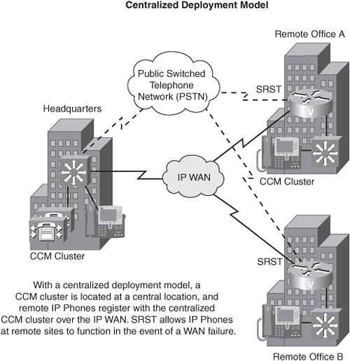
When you have multiple sites (for example, a main headquarters site and remote office sites) that contain IP phones, those CCMs can be located centrally at the headquarters location. In such an example, IP phones at the remote sites register with CCMs over the WAN link. If the WAN were to go down, these phones would lose connectivity with the headquarters site. To preserve basic service for those IP phones at remote sites, you can configure Survivable Remote Site Telephony (SRST), which allows a Cisco router to stand in for a CCM and perform basic functions in the event of a WAN outage.
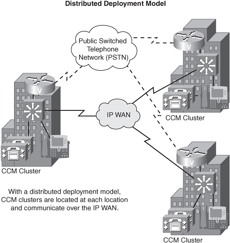
Although a centralized deployment can minimize the number of CCMs that must be purchased, the IP WAN is a potential point of failure. Therefore, you can choose a distributed deployment model, in which you have CCMs at all remote offices. In this example, if a WAN link were to fail, the remote offices’ IP phones maintain connectivity to local CCMs, and they still can route calls out to the PSTN by leveraging, for example, FXO ports on a Cisco router acting as a gateway.