
The Mechanics of Analog and Digital Voice Circuits
Introduction
In the previous section, you were introduced to analog and digital voice connections. Now, the material gets more specific and examines the electrical characteristics of these connections.
Analog Voice
First, consider the following types of signaling that are present in the analog telephony world:
• Supervisory signaling—Indicates the on-hook or off-hook condition of a phone, based on whether loop current is flowing. In addition, “ringing” is considered to be supervisory signaling. Ringing voltage is sent from the phone switch to alert the destination phone that it is receiving an incoming call. In the United States, the pattern of ringing (that is, ring cadence) is 2 seconds on and 4 seconds off.
• Address signaling—Allows a phone to dial (that is, specify the address of) a destination phone. The older method of dialing digits was with a rotary phone, which used “pulse” dialing. Pulse dialing rapidly opens and closes the tip-and-ring circuit. This series of open and closed circuit conditions within specific timing parameters indicates a dialed digit.
A more efficient approach to address signaling is dual-tone multi-frequency (DTMF) dialing. With DTMF, two simultaneous frequencies are generated, and this combination of frequencies is interpreted by the phone switch as a dialed digit. For example, the combination of a 697-Hz tone and a 1209-Hz tone indicates a dialed digit of 1.
• Information signaling—Like DTMF, information signaling uses combinations of frequencies to, in this case, indicate the status of a call (that is, to provide information to the caller). For example, a busy signal is a combination of a 480-Hz tone and a 620-Hz tone, with on/off times of 0.5/0.5 seconds.
In the previous section, you were introduced to the concept of a trunk, which interconnected phone switches. Also, you saw how loop-start signaling seized a line when loop current began to flow, and how ground-start signaling seized a line by giving its tip lead a ground potential. However, consider E&M signaling more closely. Five types of E&M signaling exist (that is, Type I through Type V), and these types define such things as the number of wires used for an E&M circuit and the polarity of those wires. Note that the voice path does not use the E&M leads. The E&M leads are intended only for signaling.
With E&M, three types of signaling can occur over the E&M leads: wink start, immediate start, and delay start. However, the most common type of E&M signaling is wink start. With wink-start signaling, the calling equipment (for example, the router) seizes a line by applying voltage to its M lead. The called equipment (for example, the PBX) “winks” by toggling its M lead on and off. When the calling equipment sees this wink, it sends its dialed digits across the voice path.
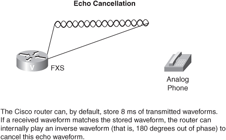
Voice ports on voice-enabled Cisco routers also can help you with the problem of echo. An impedance mismatch in a 2-wire–to–4-wire hybrid circuit (such as those found in analog phones) is the typical cause of echo. Fortunately, Cisco routers can listen to the analog voice waves that are being sent out of, for example, an FXS port. If that same waveform comes back into the router (within 8 ms by default on pre-IOS 12.3 platforms), the router interprets the waveform as echo and cancels the echo by internally playing an inverse waveform (that is, a waveform that is 180 degrees out of phase with the echo waveform).
Digitizing the Spoken Voice
To transmit the spoken voice across a digital network or an IP network, you need to digitize the analog speech patterns. In this section, you see how this conversion happens. Also, you might want to conserve WAN bandwidth by compressing those now-digitized voice packets.
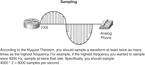
To digitize an analog waveform, you periodically take samples of the analog waveform’s amplitude. However, the question is this: How many samples should you take? The Nyquist Theorem, developed by Harry Nyquist in 1933, says that you need to sample at a rate that is at least twice as high as the highest frequency that is being sampled. For voice, in theory, the highest sampled frequency is 4 kHz. Therefore, the Nyquist Theorem indicates that you need to take 8000 samples per second, which means that you need to take a sample every 125 microseconds.
These samples, consisting of a single frequency, have amplitudes equaling the amplitudes of the sampled signaling at the instant of the sampling. This is called Pulse Amplitude Modulation (PAM). The next step is to take these PAM amplitudes and assign them a number, which can be sent in binary form. The process of assigning a number to an amplitude is called quantization.
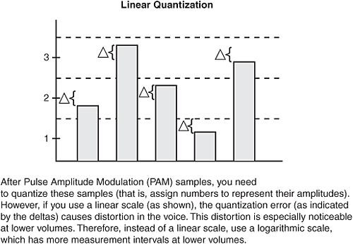
To assign a number to these samples, you establish logarithmic thresholds, and you assign numbers to samples whose amplitudes fall between specific thresholds. Because this process is really “rounding off” to a threshold value, you are introducing quantization error, which adds noise (that is, hissing) to the signal. This hissing is reduced, because a logarithmic scale is being used, and small signals are more likely to occur than large signals. Also, large signals tend to mask the noise.
After the analog waveforms have been digitized, you might want to save WAN bandwidth by compressing those digitized waveforms. The processes of encoding and decoding these waveforms are defined by codecs. The various forms of waveform compression are as follows:
• Pulse Code Modulation (PCM)—Does not actually compress the analog waveform. Rather, PCM samples and performs quantization (as previously described) with no compression. The G.711 codec uses PCM.
• Adaptive Differentiated PCM (ADPCM)—Uses a “difference signal.” Instead of encoding an entire sample, ADPCM can send the difference in the current sample versus the previous sample. G.726 is an example of an ADPCM codec.
• Conjugate Structure Algebraic Code Excited Linear Predication (CS-ACELP)—Dynamically builds a codebook based on the speech patterns. It then uses a “look-ahead buffer” to see whether the next sample matches a pattern that is already in the codebook. If it does, the codebook location can be sent, instead of the actual sample. G.729 is an example of a CS-ACELP codec.
• Low-Delay Conjugate Excited Linear Predication (LDCELP)—Is similar to CS-ACELP. However, LDCELP uses a smaller codebook, resulting in less delay but requiring more bandwidth. G.728 is an example of an LDCELP codec.
Working with Cisco products, you normally use G.711 (which requires 64 kbps of bandwidth for voice payload) in the LAN environment and G.729 (which requires 8 kbps of bandwidth for voice payload) over the WAN. G.729 has a couple of variants. Although all forms of G.729 require 8 kbps of bandwidth, G.729a uses a less-complex algorithm, which saves processor resources with slight quality degradation. G.729b enables voice activity detection (VAD), which suppresses the sending of silence if a party in the conversation does not speak for, by default, 250 ms.
Codecs vary in their bandwidth requirements, and in their quality. To measure quality, you can use a mean opinion score (MOS), which uses a “trained ear” to judge the quality of voice after passing through the codec that is being tested. MOS values range from 1, for unsatisfactory quality, to 5, for no noticeable quality degradation. For toll-quality voice, however, an MOS value in the range of 4 is appropriate. The G.711 codec has an MOS value of 4.1. Accompanied by a significant bandwidth savings, G.729 has an MOS of 3.92, while the less-processor-intensive G.729a has an MOS of 3.9.
The challenge with MOS is that at its essence, it is based on opinion. Another approach to quality measurement is Perceptual Speech Quality Measurement (PSQM), which digitally measures the difference in the original signal and the signal after it passes through a codec.
Digital Signaling
Previously, you reviewed how analog signaling (for example, loop-start) functions. Next, consider digital signaling. On a T1 circuit, each frame (including the framing bit) is 193 bits. Typically, you use a framing approach called extended super frame (ESF), which groups 24 of those standard 193-bit frames together. Because the frames are grouped, you do not need all 24 framing bits. Therefore, you can use robbed-bit signaling (that is, channel associated signaling [CAS]) to send signaling information in the framing bit of every sixth frame. Specifically, you can use the framing bit from frames 6, 12, 18, and 24 in an ESF for signaling purposes.
Alternatively, T1s can use common channel signaling (CCS), which supports 23 voice channels and one channel, the 24th channel, that is dedicated to carrying only signaling information.
An E1 circuit has 32 channels, and you can use up to 30 of them for voice. The first channel (that is, time slot 0) is used for framing information; the 17th channel (that is, time slot 16 or TS 16) carries signaling information.
In a CAS implementation, one frame might use channel 17 to carry signaling information for channels 2 and 18, while the next frame uses channel 17 to carry signaling information for channels 3 and 19.
With a CCS E1 implementation, the 17th channel (that is, TS 16) is dedicated to carrying signaling information for all other channels that use a protocol called Q.931. ISDN is an example of a CCS technology, which reserves its D channel to carry signaling information.
Whereas the Q.931 signaling protocol is often used from a customer site to a CO, the Q-Signaling (QSIG) protocol is a standards-based approach to signaling between different PBX vendors.
You can also encounter the Digital Private Network Signaling System (DPNSS) protocol, which also can interconnect PBXs. DPNSS was developed by European PBX vendors in the early 1980s, which was before ISDN standards were established. Numerous Cisco IOS gateways can function in a DPNSS network, because DPNSS can run over a standard ISDN interface.
COs typically use Signaling System 7 (SS7) as the signaling protocol between CO switches. For VoIP networks, you can use Signaling Transport (SIGTRAN) to send SS7 messages over an IP network. Specifically, SIGTRAN transports these SS7 messages using a Layer 4 protocol called Stream Control Transport Protocol (SCTP).
The Challenge of Compressing Nonvoice Streams
Although codecs such as G.729 do a great job of compressing voice, they are not designed to compress nonvoice signals such as fax or modem tones. Fax and modem information can be transmitted using G.711 without a problem, but the G.729 codec corrupts these signals to a point where they cannot be interpreted.

Cisco has a proprietary solution for this situation, called Cisco Fax Relay. With Cisco Fax Relay, the router’s DSPs hear the fax tones and do not compress those tones using G.729. A similar industry-standard approach is T.38 Fax Relay. As an additional benefit, Cisco routers can send faxes to PCs and servers that are configured with T.38 fax software.
Another approach to sending faxes across the WAN is T.37 Fax Store and Forward. With the T.37 approach, a Cisco router (called an on-ramp) can convert fax data into a TIFF attachment in an e-mail message and transmit that attachment to a store-and-forward e-mail server. This server can then deliver the fax e-mail messages to an off-ramp Cisco router, which initiates a session with the destination fax machine.
To transmit modem tones across a WAN when you have specified the G.729 codec for voice traffic, you can use modem relay, which sends modem information through the Simple Packet Relay Transport (SPRT). The last-hop router then remodulates the data and sends it to the destination router.