
Configuring Router Voice Ports
Introduction
Now that you understand, in theory, the operation of various voice interfaces, in this section, you review the configuration of these interfaces on Cisco voice-enabled routers. First, consider the following categories of voice calls:
• Local calls—Occur when both the calling and called phones are attached to the same router.
• On-net calls—Span more than one router. Specifically, the calling phone is attached to one router, and the called phone attaches to a different router. In this case, routers are part of the same network.
• Off-net calls—Originate on a router but terminate on the PSTN.
• Private Line Automatic Ringdown (PLAR) calls—Occur when a caller picks up a phone and the phone automatically dials a preconfigured number.
• PBX-to-PBX calls—Are on-net calls, where the source and destination are PBXs.
• CallManager-to-CallManager calls—Occur when IP phones register with Cisco CallManagers (CCMs) and one CCM forwards a call to another CCM.
• On-net to off-net calls—Originally intend to be on-net calls. However, because of conditions such as WAN oversubscription or a WAN outage, the call is diverted off-net (for example, to the PSTN).
Analog Voice Ports
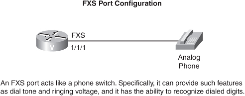
A phone connects to an FXS port, just as a phone would connect to a PBX or the PSTN. Therefore, you can configure parameters such as signal type (that is, loop-start or ground-start), ring pattern, impedance (to match the impedance of the connecting device), and call progress tones (for example, what a busy signal sounds like). Consider the following FXS configuration example.
Router(config)#voice-port 1/1/1
Router(config-voiceport)#signal loopstart
Router(config-voiceport)#impedance 600r
Router(config-voiceport)#ring cadence pattern02
Router(config-voiceport)#output attenuation -2
Router(config-voiceport)#input gain 3
Router(config-voiceport)#echo-cancel coverage 32
In this example, voice port 1/1/1 is an FXS port, and you are specifying that it should use loop-start signaling, as opposed to ground-start. Also, the impedance is set to 600 ohms resistive (that is, no capacitive component). The ringing pattern is set to the predefined pattern02, which specifies a cadence of 1 second on and 4 seconds off. Because you want the volume of VoIP calls to be approximately the same as the volume of the calls in a PBX environment (to make the VoIP network as transparent to the users as possible), you can make gain and attenuation adjustments. In this example, you are attenuating the volume of calls that are being sent out of the port to the attached phone by 2 decibels (dB), with the output attenuation command. The input gain command, in this example, is increasing the volume of the waveforms that are coming from the phone into the router by 3 dB.
To combat echo, instead of the default 8-ms period of time during which a router can recognize an incoming waveform as echo, you are increasing the coverage to 32 ms, with the echo-cancel coverage command. Finally, to maximize echo cancellation, you enabled the nonlinear feature, which suppresses all incoming waveforms from the phone until the volume is loud enough to be interpreted as speech. Note that this nonlinear feature can lead to “clipping” when the other party begins to speak. You can enter the nonlinear feature with the non-linear voice-port configuration-mode command.
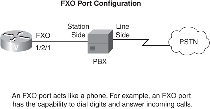
An FXO port connects to a phone switch (for example, a CO switch or PBX). Therefore, an FXO port acts like a phone. Typical parameters that you can configure on an FXO port are signaling (which must match the signaling type of the phone switch to which you are connecting), dial type (that is, DTMF or pulse), and the number of incoming rings before the FXO port answers (that is, goes off-hook). Consider the following FXO configuration example.
Router(config)#voice-port 1/2/1
Router(config-voiceport)#signal loopstart
Router(config-voiceport)#ring number 3
Router(config-voiceport)#dial-type pulse
In this example, voice port 1/2/1 is an FXO port, and you are specifying that it should use loop-start signaling. Also, because the FXO port acts like a phone, you can specify how many rings it receives before it answers. In this case, the FXO port will answer after 3 rings. Also, when the FXO port dials, it is configured to use pulse dialing.
An E&M port typically connects to an existing E&M port on a PBX. Typical parameters that you can configure on an E&M port include the signaling type (for example, wink start), the E&M type (that is, 1, 2, 3, or 5), and the number of wires that are used for the voice path (that is, the “operation”). Consider the following E&M configuration:
Router(config)#voice-port 2/1/1
Router(config-voiceport)#type 1
Router(config-voiceport)#operation 4-wire
Router(config-voiceport)#signal wink-start

In this example, an E&M port is configured as E&M Type I. In addition, the voice path, which does not use the E&M leads, uses four wires, meaning that both the tip and ring leads have their own return path. The default signaling method of wink start is specified also.
Numerous timing options can be configured for Cisco voice ports. For example, consider the following configuration:
Router(config)#voice-port 1/1/1
Router(config-voiceport)#timeouts interdigit 20
Router(config-voiceport)#timeouts initial 20
Router(config-voiceport)#timeouts call-disconnect 20
In this example, voice port 1/1/1 is an FXS port. The interdigit parameter determines the maximum number of seconds allowed between dialed digits. The initial parameter specifies how long the caller can receive a dial tone before he dials the first digit. Finally, the call-disconnect parameter indicates how long this port remains in an off-hook condition if the other party disconnects first. All units of measure in this example are seconds.
Digital Voice Ports
Digital voice interfaces, such as T1, E1, and ISDN interfaces, have unique interface-specific configuration parameters. These parameters can include the type of line coding (for example, B8ZS) and framing (for example, ESF) that is used on the digital circuit. Consider the following T1 configuration example, noting that a T1 is configured from controller-configuration mode, as opposed to interface- or voice-port configuration mode.

Router(config)#controller 2/0
Router(config-controller)#clock source line
Router(config-controller)#framing esf
Router(config-controller)#linecode b8zs
In this example, T1 controller 2/0 gets its clocking from the network, as indicated by the clock source line command. In addition, the T1 is configured for extended superframing (ESF) and B8ZS line coding.
Sometimes, PBXs use proprietary signaling approaches that a Cisco router cannot interpret. In such a situation, you can configure transparent common channel signaling (T-CCS). With T-CCS, the router allows PBX signaling to flow through the router with no codec manipulation. In controller-configuration mode, you can specify that a T1 is carrying signaling, in the 24th channel, from an external source with the following command:
Router(config-controller)#ds0-group 1 timeslots 24 type
ext-sig
In the next section, you learn about the concept of a dial peer, which tells a Cisco router how to send voice packets that are destined for a specific phone number. However, for the sake of completion, a dial-peer configuration-mode command is introduced that is required for the T-CCS configuration. In dial-peer configuration mode, you need to tell the router to transmit the specified signaling channel with no manipulation (for example, from a codec) with the following command:
Router(config-dial-peer)#codec clear-channel
For verification and troubleshooting purposes, consider the following commands:
• show voice port—Displays detailed settings for the voice ports
• show voice port summary—Displays a concise view of the installed voice ports
• show voice dsp—Displays the codecs that are currently being supported by the router’s digital signal processors (DSPs)
• show controller {T1 | E1}—Displays the operating parameters for T1 and E1 controllers
• show isdn status—Displays Layer 1, 2, and 3 information for an ISDN interface
Various test commands are also available for troubleshooting purposes. For example, you can force a voice port to send ringing voltage with the following command:
Router#test voice port 1/1 relay ring on
You also can play a tone out to an attached phone with the following command:
Router#test voice port 1/1 inject-tone local 500hz
Note that other frequencies can be specified. You can even cause a gateway to dial a number with the csim start number command. For example, you could enter the csim start 5551212 command to cause the router to place a call to a destination phone number of 555-1212. This command is “hidden,” meaning that it does not appear in the IOS’s context-sensitive help. Cisco also warns that this command occasionally can cause a router to crash. Therefore, use this command with caution.