
Gateway Protocols
Introduction
In this section, you learn about the theory and configuration of the following gateway control protocols: H.323, SIP, and MGCP. The discussion begins with a generic overview of gateway protocols.
Gateway Protocol Theory
The ultimate goal of call control is to allow RTP streams to flow directly between endpoints. Therefore, during the call setup process, each endpoint (for example, IP phone) needs to learn the IP address and UDP port to use to get a phone call to the other end.
In addition to setting up a call, you might want to perform call administration and accounting features. These features can keep track of bandwidth usage on the WAN and maintain call records, which you can use for billing or planning purposes. You also might need a way to obtain status information about a current call.
Although your local gateway might know how to reach local phones, the gateway might need to contact an external database of addresses to resolve the location of a remote phone. This external database can learn about remote phones by having the gateway that is used by those remote phones register those phone numbers with the database. By having this central repository of phone number–to–IP address mappings, less configuration needs to be performed on each of the local gateways.
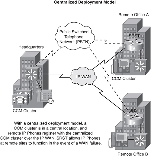
In the Cisco IP telephony environment, the Cisco CallManager (CCM) acts as a database that can direct a gateway (for example, a Cisco voice-enabled router) to a remote gateway that is connected to the destination phone. If all the CCMs are in a single location, that deployment model is called centralized call control.
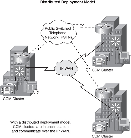
However, if CCMs are scattered across all your remote office locations, that deployment model is referred to as distributed call control. You can incur additional costs with a distributed call control model, because of the extra equipment and administration required. However, you enjoy greater scalability with the distributed call control model.
Consider the following pros and cons of each approach:
• Centralized call control
Pros:
• Less expensive
• Easier to maintain
Cons:
• Single point of failure
• Less scalable
• Uses WAN bandwidth for call setup
• Distributed call control
Pros:
• More fault tolerant
• Does not consume WAN bandwidth for call setup
• More scalable
Cons:
• Requires additional equipment
• Requires more work to perform updates
H.323 Theory and Configuration
H.323 is not a single protocol. Rather, it is a suite of protocols. This suite specifies such things as audio/video codecs and call signaling.
You should be aware of the following two major protocols:
• H.225—Performs call setup and Registration, Admission, and Status (RAS) functions
• H.245—Performs call control, including a capabilities exchange
In addition to various protocols, H.323 identifies the physical components of a IP telephony network, as follows:
• Terminals—An H.323 terminal is an end-user device that communicates with another end-user device. By definition, an H.323 terminal must support the G.711 codec.
• Gateways—A gateway (GW) converts between different audio formats/signaling. For example, on one side of the GW, you might use H.225 and H.245 signaling, and the other side of the GW might use E&M wink-start signaling.
• IP-to-IP gateways—These gateways allow different VoIP networks to interconnect. For example, if two companies had their own internal VoIP network with their own service provider, an IP-to-IP gateway could allow the two companies to join their VoIP networks. This solution requires no extension-number overlapping between the two companies.
• Gatekeepers—To prevent voice calls from oversubscribing the WAN bandwidth, groups of routers, called zones, can be identified. Then, a gatekeeper (GK) can keep track of the number of calls made from one zone to another, or calls made within a zone. Based on the available bandwidth within or between zones, a GK can permit or deny a call attempt. The gatekeeper also can perform centralized E.164 number resolution.
• Multipoint Control Units (MCUs)—An MCU supports conference calling by adding and removing participants from a call and by mixing voice streams together.
Gatekeepers are optional components, because you can have an H.323 GW directly communicate with another H.323 GW. However, this approach has scalability limitations. If you introduce GKs into the network, GWs communicate with GKs using the RAS channel. In larger topologies, you can have multiple GKs, and those GKs communicate with each other using the RAS channel.
Consider how a call is completed in the following H.323 networks:
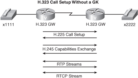
• GW-to-GW calls—This topology does not require a GK. Specifically, both GWs communicate directly with each other. First, H.225 performs the call setup, followed by H.245 performing a capabilities exchange. However, this negotiation requires numerous packet exchanges between the GWs. Another option is to use H.323 Fast Connect, which performs call setup and does a capabilities exchange in a single exchange of messages between the two GWs.
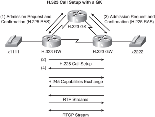
• GW-to-GK-to-GW calls—With a GK in your topology, the originating GW requests permission from the GK to place a call using an admission request (ARQ) message, after which the GK can send an admission confirm (ACF) or admission reject (ARJ) message. If permission is granted, the call setup proceeds. The destination GW also sends an ARQ to the GK. If permission is granted, the call setup proceeds as usual, using H.225 and H.245, after which RTP is used to stream audio directly between the GWs.
For even larger environments, you can have multiple GKs involved in the call setup. The main difference with such a configuration is that when the first GK gets an admission request, it sends a location request (LRQ) and must receive a location confirm (LCF) from the remote GK before sending an admission confirm (ACF) to the originating GW.
To increase the availability of H.323 networks, you can configure multiple GKs and GWs to service the same phone numbers. You also can use high-availability technologies such as Hot Standby Router Protocol (HSRP) to maintain uptime in an H.323 network.
Numerous options are available to you when configuring H.323 GWs and GKs. For a thorough example, visit http://www.cisco.com/warp/public/788/voip/2zone_gw_gk.pdf.
However, use the following three basic steps to configure an H.323 GW:
1. Enable the GW using the gateway command in global-configuration mode.
2. Configure the relationship between the GW and the GK with the h323-gateway voip id command in interface-configuration mode.
3. Configure dial peers to point to the GK, with the session target ras command.
You can verify and troubleshoot an H.323 configuration with various show commands, as follows:
• show gatekeeper calls—Displays current phone calls that the GK participated in
• show call active voice [brief]—Displays details for current voice calls
• show call history voice [last n | record | brief]—Displays call record logs
SIP Theory and Configuration
Session Initiation Protocol (SIP) uses the concept of inviting participants into sessions, and those sessions can be advertised by Session Announcement Protocol (SAP). Like H.323, SIP is a peer-to-peer protocol. These peers are called User Agents (UAs). The two types of UAs are as follows:
• User Agent Clients (UACs)—Initiate the connection by sending an INVITE message
• User Agent Servers (UASs)—Reply to INVITE messages
SIP also leverages the following types of SIP servers:
• Proxy server—Performs forwarding for a UAC
• Registrar server—Registers the location of current clients
• Redirect server—Informs the UA of the next server to contact
• Location server—Performs address resolution for SIP proxy and redirect servers
SIP uses clear text for sending messages; the two types of SIP messages are as follows:
• Request—A message from a client to a server
• Response—A message from a server to a client
A request includes messages such as an INVITE (which requests a participant to join the session) or a BYE (which disconnects the current call). Conversely, a response message uses HTML status messages. For example, you probably have attempted to connect to a website and received a “404 error” or a “500 error.” Those same types of responses are used in the SIP environment.
For a SIP client to get the IP address of a SIP server, it has to resolve a SIP address. These addresses are actually URLs that begin with “sip:” as opposed to “http:” which is commonly used in web browsers. SIP addresses can include a variety of information, such as username, password, host name, IP address, and phone number. Following is an example of a SIP address:
sip:[email protected];user=phone
In this example, the user=phone argument specifies that the user portion of the URL (that is, 18595551212) is a phone number and not a user ID.
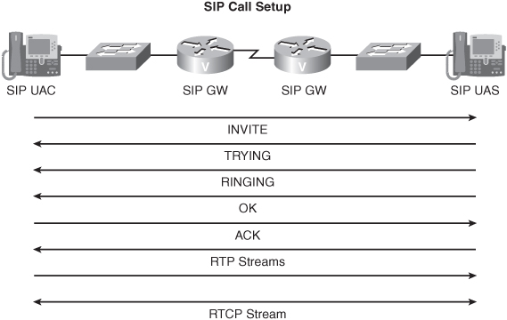
SIP devices can make their addresses known dynamically by registering with a SIP registrar server. When SIP devices have their addresses registered, a SIP client can resolve a SIP address by itself, perhaps through DNS or through a local host table. However, a SIP client can use a SIP proxy server to query a SIP location database to resolve the SIP IP address. Consider a basic SIP call, where one SIP GW communicates directly with another SIP GW, without the use of proxy or redirect servers.
The basic call setup begins when a SIP client sends an INVITE to a SIP server (noting that a SIP IP phone can act as either a client or server, depending on whether it is originating or terminating the call). The destination server (that is, a UAS) responds if it is willing to join the session to which it has been invited. The originating client (that is, a UAC) sends an acknowledgment (that is, and ACK message) to the destination server, and at this point, the RTP streams can flow directly between the SIP GWs.
If you introduce a SIP proxy server into your topology, the call setup procedure is similar to that just discussed. However, the INVITE is sent to the proxy server rather than the destination UAS. The proxy server can consult a location server to learn the IP address of the final endpoint. The destination exchanges call parameters with the proxy server, which responds to the originating UAC. The UAC then forwards an ACK through the proxy server to the destination UAS, after which the RTP stream is established.
When you use a redirect server, the originating UAC sends an INVITE message to a redirect server, which can consult a location server to determine the path to the destination. The registrar server responds to the UAC with a moved message, telling the UAC the IP address of the destination UAS. This operation is much like when you connect to a website and you receive a message saying that the page you are looking for has moved to a new URL; then you are redirected automatically to the new URL. When the UAC learns the location of the destination UAS, a direct connection can be set up between the UAC and UAS. Therefore, the main purpose of a redirect server is essentially to off-load the IP resolution procedure from the UAC.
If one of your SIP servers goes down, the voice network could be rendered unavailable. One way to provide redundancy is to have multiple instances of proxy and redirect servers. Therefore, the UAs can have multiple entries, and if the first server fails, the second server takes over.
Use the following two basic steps to configure SIP on a Cisco router:
1. Enable the UA.
2. Configure dial peers.
Consider the following example:
Router(config)#sip-ua
Router(config-sip-ua)#sip-server dns:SERVER1
Router(config-sip-ua)#dial-peer voice 1 voip
Router(config-dial-peer)#destination-pattern 5...
Router(config-dial-peer)#session protocol sipv2
Router(config-dial-peer)#session target sip-server
In this example, you enable the SIP UA with the sip-ua global-configuration-mode command. Then, you specify the DNS name of your SIP server with the sip-server command. When the SIP server has been defined, in VoIP dial-peer configuration mode, you specify that you want the dial peer to use SIP version 2, with the session protocol sipv2 command. Finally, instead of specifying an IP address as the session target, you use the session target sip-server command, which points your dial peer to the SIP server that is defined under sip-ua configuration mode.
In addition to the show call commands that you used for H.323 verification, you can also use the show sip-ua statistics command to display three different sets of statistics (that is, SIP response statistics, SIP total traffic statistics, and retry statistics).
MGCP Theory and Configuration
Whereas H.323 and SIP were peer-to-peer protocols, MGCP is more of a client-server approach to call control. Specifically, MGCP allows GWs to point to a centralized call agent for processing. In a Cisco environment, this centralized call agent is the Cisco CallManager (CCM).

The physical pieces that make up an MGCP network, such as call agents, gateways, and endpoints, are called components. However, the logical pieces of an MGCP network, such as calls and connections, are called concepts. First, consider the following MGCP components:
• Endpoints—An endpoint is where you interface between the VoIP network and the traditional telephony network. For example, an FXS port that connects to a telephone would be considered an endpoint. Endpoint names look much like an e-mail address (for example, [email protected]). These names are composed of two parts the locally significant name of the endpoint (before the @ sign) and the DNS name of the MGCP GW (after the @ sign).
• Gateways—Gateways are in charge of converting audio between a VoIP network and a circuit-switched network. For example, a residential gateway supports devices that you typically find in residential environments (for example, POTS telephones).
• Call agents—A call agent is the intelligence of an MGCP network and controls the gateways and their endpoints. An MGCP gateway can report events to the call agent, and the call agent can, for example, tell the endpoint what type of signaling to send to the phone.
Recall that an MGCP concept is a logical piece of an MGCP network. Consider the following MGCP concepts:
• Call—A call is formed when two or more endpoints are interconnected.
• Events—An event is what an endpoint has been instructed (by the call agent) to watch for. As an example, an FXS port might notice the event of an attached POTS device going off-hook.
• Signal—A call agent instructs an endpoint to send a specific signal when a certain event occurs. For example, after the event of a POTS phone going off-hook, the call agent might instruct the FXS endpoint to send the signal of “dial tone” to the phone.
MGCP groups relevant events and signals into packages. For example, a line package contains events and signals that are used on subscriber lines, such as an off-hook event and a dial-tone signal. MGCP GW types are defined by the types of packages that they support. For example, a trunk gateway supports the generic media, DTMF, trunk, and RTP packages.
You do not have to configure an MGCP GW with dial peers for every destination phone number. Instead, the GW can send each dialed digit to the call agent, until a match is made. However, that approach can put a heavy burden on the call agent. An alternate approach is for the gateway to download a digit map, which is essentially a copy of the dial plan that is contained in the call agent. When a GW has a digit map, it then has the responsibility of collecting all the dialed digits and finding a pattern match.
To enhance the availability of an MGCP network, survivability strategies such as “MGCP switchover and switchback” and “MGCP gateway fallback” are supported. MGCP switchover and switchback uses two or more CCMs. When a GW sees no MGCP messages from a call agent for a period of time, the GW attempts to establish a connection with a backup CCM. If the primary CCM comes back up, the GW can be configured to switch back to the primary.
MGCP gateway fallback works with SRST to maintain a remote office that connects to a centralized CCM. If the WAN link, which the GW uses to reach the CCM, fails, the GW relies on a fallback H.323 configuration that provides basic functionality for attached IP phones.
MGCP is enabled in global-configuration mode with the mgcp command. The IP address of the call agent then is specified with the mgcp call-agent ip_address command. When MGCP is enabled, you specify which packages the GW expects the call agent to use when communicating with the GW. Consider the following configuration example, where you are specifying that a router is acting as an MGCP GW and that its call agent is located at IP address 10.1.1.1:
Router(config)#mgcp
Router(config)#mgcp call-agent 10.1.1.1
A POTS dial peer that MGCP uses does not have a destination-pattern command. Rather, it uses the application MGCPAPP command to indicate that the port specified by the dial peer is controlled by an MGCP call agent. To view information about current MGCP connections on a GW, you can use the show mgcp connection command.
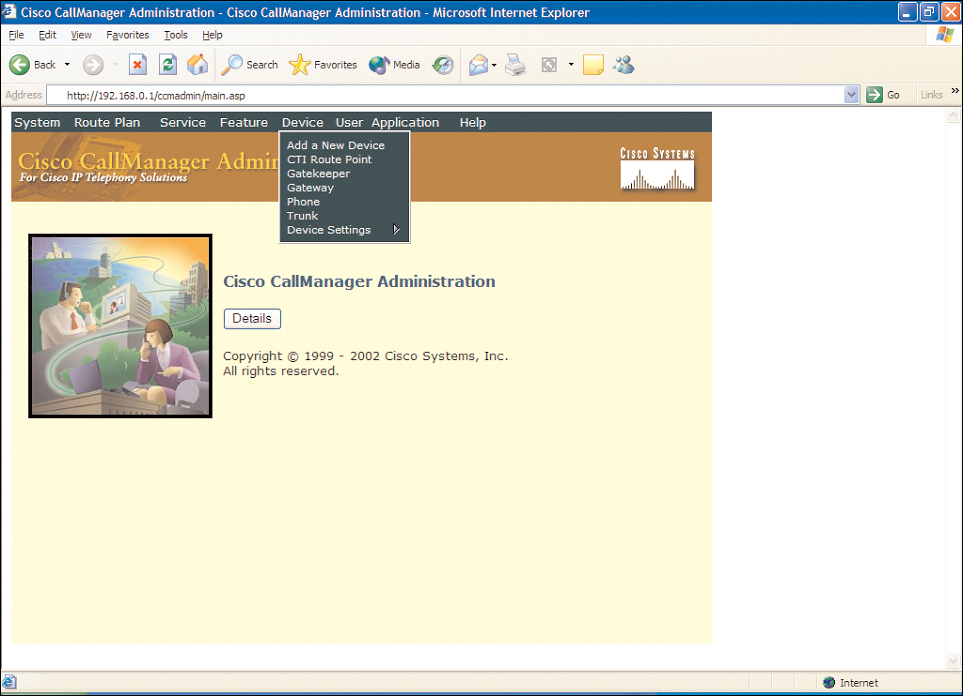
In a Cisco environment, because an MGCP gateway works in conjunction with a Cisco CallManager (CCM), the following items need to be configured on the CCM:
• From the CCM main screen, choose the Device menu and select Gateway.
• Click the Add a New Gateway link.
• Select the Gateway Type from the drop-down menu, and click Next. (Note that by selecting the appropriate hardware, the CCM automatically determines that you are using MGCP.)
• In the Domain Name field, enter the DNS name of the gateway router.
• Select the appropriate CCM group from the Cisco CallManager Group menu.
• From the Module in Slot 1 drop-down menu, select the appropriate installed module, and click the Insert button.
• After the screen refreshes, you see one or more “subunits” listed below the module that you specified. Select the appropriate subunit(s) from the Subunit drop-down menu(s), and click the Update button.
• After the screen refreshes, you see one or more “endpoint identifiers” that correspond to physical voice ports on the router. Click an Endpoint Identifier link.
• Select the appropriate Device Pool from the drop-down menu, and click the Insert button.
• For an FXS port, after the screen refreshes, click the Add DN link to add a directory number. Enter the directory number (that is, phone number) for the voice port in the Directory Number field, and click the Insert button.
At this point, the Cisco MGCP gateway and the CCM (acting as the MGCP call agent) can communicate between themselves using MGCP signaling.
Selecting a Gateway Protocol
When selecting from the three call control protocols (that is, H.323, SIP, and MGCP), consider the following characteristics:
• H.323
• Mature
• Uses Abstract Syntax Notation 1 (ASN.1) for call control messages
• Uses a peer-to-peer model
• Scales well in an enterprise
• SIP
• Not as mature as H.323
• Uses clear text for call control
• Uses a peer-to-peer model
• Allows interoperability between diverse vendor equipment
• Not as mature as H.323
• Uses clear text for call control
• Uses a client-server model
• Ideally positioned for service providers (because of centrally located call agents)