CHAPTER 3
Security Architecture and Engineering
This chapter presents the following:
• System architecture
• Trusted computing base and security mechanisms
• Information security software models
• Assurance evaluation criteria and ratings
• Certification and accreditation processes
• Distributed systems security
• Cryptography components and their relationships
• Steganography
• Public key infrastructure (PKI)
• Site and facility design considerations
• Physical security risks, threats, and countermeasures
• Electric power issues and countermeasures
• Fire prevention, detection, and suppression
As an engineer I’m constantly spotting problems and plotting how to solve them.
—James Dyson
Organizations today are concerned with a myriad of potential security issues, including those pertaining to the confidential data stored in their databases, the security of their web farms that are connected directly to the Internet, the integrity of data-entry values going into applications that process business-oriented information, external attackers attempting to bring down servers and affecting productivity, malware spreading, the internal consistency of data warehouses, mobile device security, advanced persistent threats, and much more. These issues have the potential to not only affect productivity and profitability, but also raise legal and liability issues. Companies, and the management that runs them, can be held accountable if a security issue arises in any one of the many areas previously mentioned. So it is, or at least it should be, very important for companies to know what security measures they need to put in place and to establish means to properly assure that the necessary level of protection is actually being provided by the products they develop or purchase.
Many of these security issues must be thought through as we develop or engineer any service or product. Security is best if it is designed and built into the foundation of anything we build and not added as an afterthought. Once security is integrated as an important part of the design, it has to be engineered, implemented, tested, evaluated, and potentially certified and accredited. The security of a product must be evaluated against the availability, integrity, and confidentiality it claims to provide. What gets tricky is that organizations and individuals commonly do not fully understand what it actually takes for software to provide these services in an effective manner. Of course a company wants a piece of software to provide solid confidentiality, but does the person who is actually purchasing this software product know the correct questions to ask and what to look for? Does this person ask the vendor about cryptographic key protection, encryption algorithms, and what software development life-cycle model the vendor followed? Does the purchaser know to ask about hashing algorithms, message authentication codes, fault tolerance, and built-in redundancy options? The answer is “not usually.” Not only do most people not fully understand what has to be in place to properly provide availability, integrity, and confidentiality, but it is very difficult to decipher what a piece of software is and is not carrying out properly without the necessary knowledge base.
This chapter covers security architecture and engineering from the ground up. It then goes into how systems are evaluated and rated by governments and other agencies, and what these ratings actually mean. We spend a good amount of time discussing cryptology, because it underlies most of our security controls. Finally, after covering how to keep our adversaries from virtually touching our systems, we also cover how to keep them from physically reaching them as well. However, before we dive into these concepts, it is important to understand what we mean by system-based architectures and the components that make them up.
System Architecture
In Chapter 1 we covered enterprise architecture frameworks and introduced their direct relationship to system architecture. As explained in that chapter, an architecture is a tool used to conceptually understand the structure and behavior of a complex entity through different views. An architecture description is a formal description and representation of a system, the components that make it up, the interactions and interdependencies between those components, and the relationship to the environment. An architecture provides different views of the system, based upon the needs of the stakeholders of that system.

CAUTION It is common for people in technology to not take higher-level, somewhat theoretical concepts such as architecture seriously because they see them as fluffy and nonpractical, and they cannot always relate these concepts to what they see in their daily activities. While knowing how to configure a server is important, it is actually more important for more people in the industry to understand how to actually build that server securely in the first place. Make sure to understand security across the spectrum, from a high-level theoretical perspective to a practical hands-on perspective. If no one focuses on how to properly carry out secure system architecture, we will be doomed to always have insecure systems.
Before digging into the meat of system architecture, we need to establish the correct terminology. Although people use terms such as “design,” “architecture,” and “software development” interchangeably, each of these terms has a distinct meaning that you need to understand to really learn system architecture correctly.
A system architecture describes the major components of the system and how they interact with each other, with the users, and with other systems. An architecture is at the highest level when it comes to the overall process of system development. It is at the architectural level that we are answering questions such as “How is it going to be used?,” “What environment will it work within?,” “What type of security and protection is required?,” and “What does it need to be able to communicate with?” The answers to these types of questions outline the main goals the system must achieve, and they help us construct the system at an abstract level. This abstract architecture provides the “big picture” goals, which are used to guide the rest of the development process.
The term development refers to the entire life cycle of a system, including the planning, analysis, design, building, testing, deployment, maintenance, and retirement phases. Though many people think of development as simply the part of this process that results in a new system, the reality is that it must consider if not include the entire cradle-to-grave lifetime of the system. Within this development, there is a subset of activities that are involved in deciding how the system will be put together. This design phase starts with the architecting effort described previously and progresses through the detailed description of everything needed to build the system.
It is worth pausing briefly here to make sure you understand what “system” means in the context of system architecture. When most people hear this term, they think of an individual computer, but a system can be an individual computer, an application, a select set of subsystems, a set of computers, or a set of networks made up of computers and applications. A system can be simplistic, as in a single-user operating system dedicated to a specific task, or as complex as an enterprise network made up of heterogeneous multiuser systems and applications. So when we look at system architectures, this could apply to very complex and distributed environments or very focused subsystems. We need to make sure we understand the scope of the target system before we can develop or evaluate it or its architecture.
There are evolving standards that outline the specifications of system architectures. In 2000, IEEE came up with a standard (Standard 1471) that was called IEEE Recommended Practice for Architectural Description of Software-Intensive Systems. This was adopted by ISO and published in 2011 as ISO/IEC/IEEE 42010, Systems and software engineering—Architecture description. The standard is evolving and being improved upon. The goal is to internationally standardize how system architecture takes place so that product developers aren’t just “winging it” and coming up with their own proprietary approaches. A disciplined approach to system architecture allows for better quality, interoperability, extensibility, portability, and security.
One of the purposes of ISO/IEC/IEEE 42010:2011 is to establish a shared vocabulary among all the stakeholders. Among these terms are the following:
• Architecture Fundamental organization of a system embodied in its components, their relationships to each other and to the environment, and the principles guiding its design and evolution.
• Architecture description (AD) Collection of document types to convey an architecture in a formal manner.
• Stakeholder Individual, team, or organization (or classes thereof) with interests in, or concerns relative to, a system.
• View Representation of a whole system from the perspective of a related set of concerns.
• Viewpoint A specification of the conventions for constructing and using a view. A template from which to develop individual views by establishing the purposes and audience for a view and the techniques for its creation and analysis.
As an analogy, if you are going to build your own house, you are first going to have to work with an architect. She will ask you a bunch of questions to understand your overall “goals” for the house, as in four bedrooms, three bathrooms, family room, game room, garage, 3,000 square feet, ranch style, etc. Once she collects your goal statements, she will create the different types of documentation (blueprint, specification documents) that describe the architecture of the house in a formal manner (architecture description). The architect needs to make sure she meets several people’s (stakeholders) goals for this house—not just yours. She needs to meet zoning requirements, construction requirements, legal requirements, and your design requirements. Each stakeholder needs to be presented with documentation and information (views) that map to their needs and understanding of the house. One architecture schematic can be created for the plumber, a different schematic can be created for the electrician, another one can be created for the zoning officials, and one can be created for you. Each stakeholder needs to have information about this house in terms that they understand and that map to their specific concerns. If the architect gives you documentation about the electrical current requirements and location of where electrical grounding will take place, that does not help you. You need to see the view of the architecture that directly relates to your needs.
The same is true with a system. An architect needs to capture the goals that the system is supposed to accomplish for each stakeholder. One stakeholder is concerned about the functionality of the system, another one is concerned about the performance, another is concerned about interoperability, and yet another stakeholder is concerned about security. The architect then creates documentation that formally describes the architecture of the system for each of these stakeholders that will best address their concerns from their own viewpoints. Each stakeholder will review the architecture description to ensure that the architect has not missed anything. After the architecture description is approved, the software designers and developers are brought in to start building the system.
The relationship between these terms and concepts is illustrated in Figure 3-1.
The stakeholders for a system include (but are not limited to) the users, operators, maintainers, developers, and suppliers. Each stakeholder has his own concerns pertaining to the system, which can include performance, functionality, security, maintainability, quality of service, usability, cost, etc. The system’s architecture description needs to express the architect’s decisions addressing each concern of each stakeholder, which is done through architecture views. Each view conforms to a particular viewpoint. Useful viewpoints on a system include logical, physical, structural, behavioral, management, cost, and security, among many others.
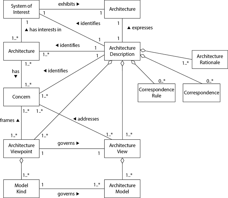
Figure 3-1 Formal architecture terms and relationships (Image from www.iso-architecture.org/42010/cm/)
The creation and use of system architect processes are evolving, becoming more disciplined and standardized. In the past, system architectures were developed to meet the identified stakeholders’ concerns (functionality, interoperability, performance), but a new concern has come into the limelight—security. So new systems need to meet not just the old concerns, but also the new concerns the stakeholders have. Security goals have to be defined before the architecture of a system is created, and specific security views of the system need to be created to help guide the design and development phases. When we hear about security being “bolted on,” that means security concerns are addressed at the development (programming) phase and not the architecture phase. When we state that security needs to be “baked in,” this means that security has to be integrated at the architecture phase.

EXAM TIP While a system architecture addresses many stakeholder concerns, we will focus on the concern of security since information security is the crux of the CISSP exam.
Computer Architecture
Computer architecture encompasses all of the parts of a computer system that are necessary for it to function, including the central processing unit, memory chips, logic circuits, storage devices, input and output devices, security components, buses, and networking interfaces. The interrelationships and internal working of all of these parts can be quite complex, and making them work together in a secure fashion consists of complicated methods and mechanisms. Thank goodness for the smart people who figured this stuff out! Now it is up to us to learn how they did it and why.
The more you understand how these different pieces work and process data, the more you will understand how vulnerabilities actually occur and how countermeasures work to impede and hinder vulnerabilities from being introduced, found, and exploited.

NOTE This chapter interweaves the hardware and operating system architectures and their components to show you how they work together.
The Central Processing Unit
The central processing unit (CPU) is the brain of a computer. In the most general description possible, it fetches instructions from memory and executes them. Although a CPU is a piece of hardware, it has its own instruction set that is necessary to carry out its tasks. Each CPU type has a specific architecture and set of instructions that it can carry out. The operating system must be designed to work within this CPU architecture. This is why one operating system may work on a Pentium Pro processor but not on an AMD processor. The operating system needs to know how to “speak the language” of the processor, which is the processor’s instruction set.
The chips within the CPU cover only a couple of square inches, but contain millions of transistors. All operations within the CPU are performed by electrical signals at different voltages in different combinations, and each transistor holds this voltage, which represents 0’s and 1’s to the operating system. The CPU contains registers that point to memory locations that contain the next instructions to be executed and that enable the CPU to keep status information of the data that needs to be processed. A register is a temporary storage location. Accessing memory to get information on what instructions and data must be executed is a much slower process than accessing a register, which is a component of the CPU itself. So when the CPU is done with one task, it asks the registers, “Okay, what do I have to do now?” And the registers hold the information that tells the CPU what its next job is.
The actual execution of the instructions is done by the arithmetic logic unit (ALU). The ALU performs mathematical functions and logical operations on data. The ALU can be thought of as the brain of the CPU, and the CPU as the brain of the computer.
Software holds its instructions and data in memory. When an action needs to take place on the data, the instructions and data memory addresses are passed to the CPU registers, as shown in Figure 3-2. When the control unit indicates that the CPU can process them, the instructions and data memory addresses are passed to the CPU. The CPU sends out requests to fetch these instructions and data from the provided addresses and then actual processing, number crunching, and data manipulation take place. The results are sent back to the requesting process’s memory address.
An operating system and applications are really just made up of lines and lines of instructions. These instructions contain empty variables, which are populated at run time. The empty variables hold the actual data. There is a difference between instructions and data. The instructions have been written to carry out some type of functionality on the data. For example, let’s say you open a Calculator application. In reality, this program is just lines of instructions that allow you to carry out addition, subtraction, division, and other types of mathematical functions that will be executed on the data you provide. So, you type in 3 + 5. The 3 and the 5 are the data values. Once you click the = button, the Calculator program tells the CPU it needs to take the instructions on how to carry out addition and apply these instructions to the two data values 3 and 5. The ALU carries out this instruction and returns the result of 8 to the requesting program. This is when you see the value 8 in the Calculator’s field. To users, it seems as though the Calculator program is doing all of this on its own, but it is incapable of this. It depends upon the CPU and other components of the system to carry out this type of activity.
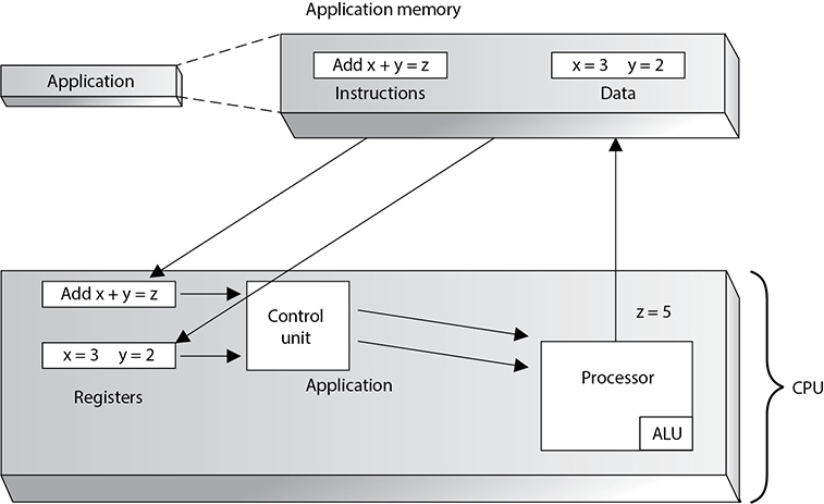
Figure 3-2 Instruction and data addresses are passed to the CPU for processing.
The control unit manages and synchronizes the system while different applications’ code and operating system instructions are being executed. The control unit is the component that fetches the code, interprets the code, and oversees the execution of the different instruction sets. It determines what application instructions get processed and in what priority and time slice. It controls when instructions are executed, and this execution enables applications to process data. The control unit does not actually process the data. It is like the traffic cop telling vehicles when to stop and start again, as illustrated in Figure 3-3. The CPU’s time has to be sliced up into individual units and assigned to processes. It is this time slicing that fools the applications and users into thinking the system is actually carrying out several different functions at one time. While the operating system can carry out several different functions at one time (multitasking), in reality, the CPU is executing the instructions in a serial fashion (one at a time).
A CPU has several different types of registers, containing information about the instruction set and data that must be executed. General registers are used to hold variables and temporary results as the ALU works through its execution steps. The general registers are like the ALU’s scratch pad, which it uses while working. Special registers (dedicated registers) hold information such as the program counter, stack pointer, and program status word (PSW). The program counter register contains the memory address of the next instruction to be fetched. After that instruction is executed, the program counter is updated with the memory address of the next instruction set to be processed. It is similar to a boss-and-secretary relationship. The secretary keeps the boss on schedule and points her to the necessary tasks she must carry out. This allows the boss to just concentrate on carrying out the tasks instead of having to worry about the “busy work” being done in the background.

Figure 3-3 The control unit works as a traffic cop, indicating when instructions are sent to the processor.
The program status word (PSW) holds different condition bits. One of the bits indicates whether the CPU should be working in user mode (also called problem state) or privileged mode (also called kernel or supervisor mode). An important theme of this chapter is to teach you how operating systems protect themselves. They need to protect themselves from applications, software utilities, and user activities if they are going to provide a stable and safe environment. One of these protection mechanisms is implemented through the use of these different execution modes. When an application needs the CPU to carry out its instructions, the CPU works in user mode. This mode has a lower privilege level, and many of the CPU’s instructions and functions are not available to the requesting application. The reason for the extra caution is that the developers of the operating system and CPU do not know who developed the application or how it is going to react, so the CPU works in a lower privilege mode when executing these types of instructions. By analogy, if you are expecting visitors who are bringing their two-year-old boy, you move all of the breakables that someone under three feet tall can reach. No one is ever sure what a two-year-old toddler is going to do, but it usually has to do with breaking something. An operating system and CPU are not sure what applications are going to attempt, which is why this code is executed in a lower privilege and critical resources are out of reach of the application’s code.
If the PSW has a bit value that indicates the instructions to be executed should be carried out in privileged mode, this means a trusted process (an operating system process) made the request and can have access to the functionality that is not available in user mode. An example would be if the operating system needed to communicate with a peripheral device. This is a privileged activity that applications cannot carry out. When these types of instructions are passed to the CPU, the PSW is basically telling the CPU, “The process that made this request is an all-right guy. We can trust him. Go ahead and carry out this task for him.”
Memory addresses of the instructions and data to be processed are held in registers until needed by the CPU. The CPU is connected to an address bus, which is a hardwired connection to the RAM chips in the system and the individual input/output (I/O) devices. Memory is cut up into sections that have individual addresses associated with them. I/O devices (optical discs, USB devices, printers, and so on) are also allocated specific unique addresses. If the CPU needs to access some data, either from memory or from an I/O device, it sends a fetch request on the address bus. The fetch request contains the address of where the needed data is located. The circuitry associated with the memory or I/O device recognizes the address the CPU sent down the address bus and instructs the memory or device to read the requested data and put it on the data bus. So the address bus is used by the CPU to indicate the location of the instructions to be processed, and the memory or I/O device responds by sending the data that resides at that memory location through the data bus. As an analogy, if Sally calls you on the telephone and tells you the book she needs you to mail to her, this would be like a CPU sending a fetch request down the address bus. You locate the book Sally requested and send it to her in the mail, which would be similar to how an I/O device finds the requested data and puts it on the data bus for the CPU to receive.
This process is illustrated in Figure 3-4.
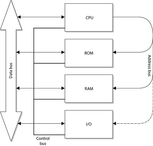
Figure 3-4 Address and data buses are separate and have specific functionality.
Once the CPU is done with its computation, it needs to return the results to the requesting program’s memory. So, the CPU sends the requesting program’s address down the address bus and sends the new results down the data bus with the command write. This new data is then written to the requesting program’s memory space. Following our earlier example, once the CPU adds 3 and 5 and sends the new resulting data to the Calculator program, you see the result as 8.
The address and data buses can be 8, 16, 32, or 64 bits wide. Most systems today use a 64-bit address bus, which means the system can have a large address space (264). Systems can also have a 64-bit data bus, which means the system can move data in parallel back and forth between memory, I/O devices, and the CPU of this size. (A 64-bit data bus means the size of the chunks of data a CPU can request at a time is 64 bits.) But what does this really mean and why does it matter? A two-lane highway can be a bottleneck if a lot of vehicles need to travel over it. This is why highways are increased to four, six, and eight lanes. As computers and software get more complex and performance demands increase, we need to get more instructions and data to the CPU faster so it can do its work on these items and get them back to the requesting program as fast as possible. So we need fatter pipes (buses) to move more stuff from one place to another place.
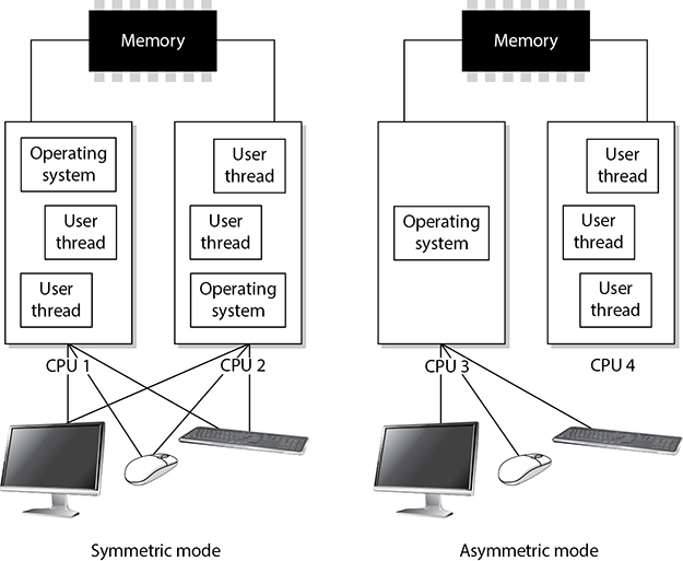
Figure 3-5 Symmetric mode and asymmetric mode of multiprocessing
Multiprocessing
Many modern computers have more than one CPU for increased performance. An operating system must be developed specifically to be able to understand and work with more than one processor. If the computer system is configured to work in symmetric mode, this means the processors are handed work as needed, as shown with CPU 1 and CPU 2 in Figure 3-5. It is like a load-balancing environment. When a process needs instructions to be executed, a scheduler determines which processor is ready for more work and sends it on. If a processor is going to be dedicated to a specific task or application, all other software would run on a different processor. In Figure 3-5, CPU 4 is dedicated to one application and its threads, while CPU 3 is used by the operating system. When a processor is dedicated, as in this example, the system is working in asymmetric mode. This usually means the computer has some type of time-sensitive application that needs its own personal processor. So, the system scheduler will send instructions from the time-sensitive application to CPU 4 and send all the other instructions (from the operating system and other applications) to CPU 3.
Memory Types
Memory management is critical, but what types of memory actually have to be managed? As stated previously, the operating system instructions, applications, and data are held in memory, but so are the basic input/output system (BIOS), device controller instructions, and firmware. They do not all reside in the same memory location or even the same type of memory. The different types of memory, what they are used for, and how each is accessed can get a bit confusing because the CPU deals with several different types for different reasons.
The following sections outline the different types of memory that can be used within computer systems.
Random Access Memory
Random access memory (RAM) is a type of temporary storage facility where data and program instructions can temporarily be held and altered. It is used for read/write activities by the operating system and applications. It is described as volatile because if the computer’s power supply is terminated, then all information within this type of memory is lost.
RAM is an integrated circuit made up of millions of transistors and capacitors. The capacitor is where the actual charge is stored, which represents a 1 or 0 to the system. The transistor acts like a gate or a switch. A capacitor that is storing a binary value of 1 has several electrons stored in it, which have a negative charge, whereas a capacitor that is storing a 0 value is empty. When the operating system writes over a 1 bit with a 0 bit, in reality, it is just emptying out the electrons from that specific capacitor.
One problem is that these capacitors cannot keep their charge for long. Therefore, a memory controller has to “recharge” the values in the capacitors, which just means it continually reads and writes the same values to the capacitors. If the memory controller does not “refresh” the value of 1, the capacitor will start losing its electrons and become a 0 or a corrupted value. This explains how dynamic RAM (DRAM) works. The data being held in the RAM memory cells must be continually and dynamically refreshed so your bits do not magically disappear. This activity of constantly refreshing takes time, which is why DRAM is slower than static RAM.

TIP When we are dealing with memory activities, we use a time metric of nanoseconds (ns), which is a billionth of a second. So if you look at your RAM chip and it states 70 ns, this means it takes 70 nanoseconds to read and refresh each memory cell.
Static RAM (SRAM) does not require this continuous-refreshing nonsense; it uses a different technology, by holding bits in its memory cells without the use of capacitors, but it does require more transistors than DRAM. Since SRAM does not need to be refreshed, it is faster than DRAM, but because SRAM requires more transistors, it takes up more space on the RAM chip. Manufacturers cannot fit as many SRAM memory cells on a memory chip as they can DRAM memory cells, which is why SRAM is more expensive. So, DRAM is cheaper and slower, and SRAM is more expensive and faster. It always seems to go that way. SRAM has been used in cache, and DRAM is commonly used in RAM chips.
Because life is not confusing enough, we have many other types of RAM. The main reason for the continual evolution of RAM types is that it directly affects the speed of the computer itself. Many people mistakenly think that just because you have a fast processor, your computer will be fast. However, memory type and size and bus sizes are also critical components. Think of memory as pieces of paper used by the system to hold instructions. If the system had small pieces of papers (small amount of memory) to read and write from, it would spend most of its time looking for these pieces and lining them up properly. When a computer spends more time moving data from one small portion of memory to another than actually processing the data, it is referred to as thrashing. This causes the system to crawl in speed and your frustration level to increase.
The size of the data bus also makes a difference in system speed. You can think of a data bus as a highway that connects different portions of the computer. If a ton of data must go from memory to the CPU and can only travel over a 4-lane highway, compared to a 64-lane highway, there will be delays in processing.
Increased addressing space also increases system performance. A system that uses a 64-bit addressing scheme can put more instructions and data on a data bus at one time compared to a system that uses a 32-bit addressing scheme. So a larger addressing scheme allows more stuff to be moved around and processed, and a larger bus size provides the highway to move this stuff around quickly and efficiently.
So the processor, memory type and amount, memory addressing, and bus speeds are critical components to system performance.
The following are additional types of RAM you should be familiar with:
• Synchronous DRAM (SDRAM) Synchronizes itself with the system’s CPU and synchronizes signal input and output on the RAM chip. It coordinates its activities with the CPU clock so the timing of the CPU and the timing of the memory activities are synchronized. This increases the speed of transmitting and executing data.
• Extended data out DRAM (EDO DRAM) This is faster than DRAM because DRAM can access only one block of data at a time, whereas EDO DRAM can capture the next block of data while the first block is being sent to the CPU for processing. It has a type of “look ahead” feature that speeds up memory access.
• Burst EDO DRAM (BEDO DRAM) Works like (and builds upon) EDO DRAM in that it can transmit data to the CPU as it carries out a read option, but it can send more data at once (burst). It reads and sends up to four memory addresses in a small number of clock cycles.
• Double data rate SDRAM (DDR SDRAM) Carries out read operations on the rising and falling cycles of a clock pulse. So instead of carrying out one operation per clock cycle, it carries out two and thus can deliver twice the throughput of SDRAM. Basically, it doubles the speed of memory activities, when compared to SDRAM, with a smaller number of clock cycles. Pretty groovy.
TIP These different RAM types require different controller chips to interface with them; therefore, the motherboards that these memory types are used on often are very specific in nature.
Well, that’s enough about RAM for now. Let’s look at other types of memory that are used in basically every computer in the world.
Read-Only Memory
Read-only memory (ROM) is a nonvolatile memory type, meaning that when a computer’s power is turned off, the data is still held within the memory chips. When data is written into ROM memory chips, the data cannot be altered. Individual ROM chips are manufactured with the stored program or routines designed into it. The software that is stored within ROM is called firmware.
Programmable read-only memory (PROM) is a form of ROM that can be modified after it has been manufactured. PROM can be programmed only one time because the voltage that is used to write bits into the memory cells actually burns out the fuses that connect the individual memory cells. The instructions are “burned into” PROM using a specialized PROM programmer device.
Erasable programmable read-only memory (EPROM) can be erased, modified, and upgraded. EPROM holds data that can be electrically erased or written to. To erase the data on the memory chip, you need your handy-dandy ultraviolet (UV) light device that provides just the right level of energy. The EPROM chip has a quartz window, which is where you point the UV light. Although playing with UV light devices can be fun for the whole family, we have moved on to another type of ROM technology that does not require this type of activity.
To erase an EPROM chip, you must remove the chip from the computer and wave your magic UV wand, which erases all of the data on the chip—not just portions of it. So someone invented electrically erasable programmable read-only memory (EEPROM), and we all put our UV light wands away for good.
EEPROM is similar to EPROM, but its data storage can be erased and modified electrically by onboard programming circuitry and signals. This activity erases only 1 byte at a time, which is slow. And because we are an impatient society, yet another technology was developed that is very similar, but works more quickly.
Flash memory is a special type of memory that is used in digital cameras, BIOS chips, memory cards, and video game consoles. It is a solid-state technology, meaning it does not have moving parts and is used more as a type of hard drive than memory.
Flash memory basically moves around different levels of voltages to indicate that a 1 or 0 must be held in a specific address. It acts as a ROM technology rather than a RAM technology. (For example, you do not lose pictures stored on your memory stick in your digital camera just because your camera loses power. RAM is volatile, and ROM is nonvolatile.) When Flash memory needs to be erased and turned back to its original state, a program initiates the internal circuits to apply an electric field. The erasing function takes place in blocks or on the entire chip instead of erasing 1 byte at a time.
Flash memory is used as a small disk drive in most implementations. Its benefits over a regular hard drive are that it is smaller, faster, and lighter. So let’s deploy Flash memory everywhere and replace our hard drives! Maybe one day. Today it is relatively expensive compared to regular hard drives.
Cache Memory
Cache memory is a type of memory used for high-speed writing and reading activities. When the system assumes (through its programmatic logic) that it will need to access specific information many times throughout its processing activities, it will store the information in cache memory so it is easily and quickly accessible. Data in cache can be accessed much more quickly than data stored in other memory types. Therefore, any information needed by the CPU very quickly and very often is usually stored in cache memory, thereby improving the overall speed of the computer system.
An analogy is how the brain stores information it uses often. If one of Marge’s primary functions at her job is to order parts, which requires telling vendors the company’s address, Marge stores this address information in a portion of her brain from which she can easily and quickly access it. This information is held in a type of cache. If Marge was asked to recall her third-grade teacher’s name, this information would not necessarily be held in cache memory, but in a more long-term storage facility within her noggin. The long-term storage within her brain is comparable to a system’s hard drive. It takes more time to track down and return information from a hard drive than from specialized cache memory.
TIP Different motherboards have different types of cache. Level 1 (L1) is faster than Level 2 (L2), and L2 is faster than L3. Some processors and device controllers have cache memory built into them. L1 and L2 are usually built into the processors and the controllers themselves.
Memory Mapping
Because there are different types of memory holding different types of data, a computer system does not want to let every user, process, and application access all types of memory anytime they want to. Access to memory needs to be controlled to ensure data does not get corrupted and that sensitive information is not available to unauthorized processes. This type of control takes place through memory mapping and addressing.
The CPU is one of the most trusted components within a system, and can access memory directly. It uses physical addresses instead of pointers (logical addresses) to memory segments. The CPU has physical wires connecting it to the memory chips within the computer. Because physical wires connect the two types of components, physical addresses are used to represent the intersection between the wires and the transistors on a memory chip. Software does not use physical addresses; instead, it employs logical memory addresses. Accessing memory indirectly provides an access control layer between the software and the memory, which is done for protection and efficiency. Figure 3-6 illustrates how the CPU can access memory directly using physical addresses and how software must use memory indirectly through a memory mapper.
Let’s look at an analogy. You would like to talk to Mr. Marshall about possibly buying some acreage in Iowa that he has listed for sale on Craigslist. You don’t know Mr. Marshall personally, and you do not want to give out your physical address and have him show up at your doorstep. Instead, you would like to use a more abstract and controlled way of communicating, so you give Mr. Marshall your phone number so you can talk to him about the land and determine whether you want to meet him in person. The same type of thing happens in computers. When a computer runs software, it does not want to expose itself unnecessarily to software written by good and bad programmers alike. Operating systems enable software to access memory indirectly by using index tables and pointers, instead of giving them the right to access the memory directly. This is one way the computer system protects itself. If an operating system has a programming flaw that allows an attacker to directly access memory through physical addresses, there is no memory manager involved to control how memory is being used.

Figure 3-6 The CPU and applications access memory differently.
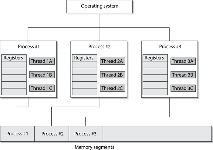
When a program attempts to access memory, its access rights are verified and then instructions and commands are carried out in a way to ensure that badly written code does not affect other programs or the system itself. Applications, and their processes, can only access the memory allocated to them, as shown in Figure 3-7. This type of memory architecture provides protection and efficiency.
The physical memory addresses that the CPU uses are called absolute addresses. The indexed memory addresses that software uses are referred to as logical addresses. And relative addresses are based on a known address with an offset value applied. As explained previously, an application does not “know” it is sharing memory with other applications. When the program needs a memory segment to work with, it tells the memory manager how much memory it needs. The memory manager allocates this much physical memory, which could have the physical addressing of 34000 to 39000, for example. But the application is not written to call upon addresses in this numbering scheme. It is most likely developed to call upon addresses starting with 0 and extending to, let’s say, 5000. So the memory manager allows the application to use its own addressing scheme—the logical addresses. When the application makes a call to one of these “phantom” logical addresses, the memory manager must map this address to the actual physical address. (It’s like two people using their own naming scheme. When Bob asks Diane for a ball, Diane knows he really means a stapler. Don’t judge Bob and Diane; it works for them.)
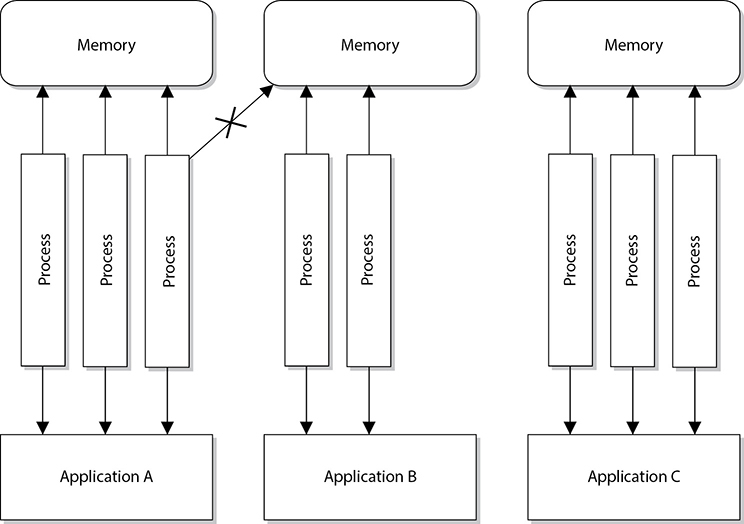
Figure 3-7 Applications, and the processes they use, access their own memory segments only.
The mapping process is illustrated in Figure 3-8. When a thread indicates the instruction needs to be processed, it provides a logical address. The memory manager maps the logical address to the physical address, so the CPU knows where the instruction is located. The thread will actually be using a relative address because the application uses the address space of 0 to 5000. When the thread indicates it needs the instruction at the memory address 3400 to be executed, the memory manager has to work from its mapping of logical address 0 to the actual physical address and then figure out the physical address for the logical address 3400. So the logical address 3400 is relative to the starting address 0.
As an analogy, if Jane knows you use a different number system than everyone else in the world, and you tell her that you need 14 cookies, she would need to know where to start in your number scheme to figure out how many cookies to really give you. So, if you inform Jane that in “your world” your numbering scheme starts at 5, she would map 5 to 0 and know that the offset is a value of 5. So when you tell her you want 14 cookies (the relative number), she takes the offset value into consideration. She knows that you start at the value 5, so she maps your logical address of 14 to the physical number of 9.

Figure 3-8 The CPU uses absolute addresses, and software uses logical addresses.
So the application is working in its “own world” using its “own addresses,” and the memory manager has to map these values to reality, which means the absolute address values.
Memory management is complex, and whenever there is complexity, there are most likely vulnerabilities that can be exploited by attackers. It is very easy for people to complain about software vendors and how they do not produce software that provides the necessary level of security, but hopefully you are gaining more insight into the actual complexity that is involved with these tasks.
Buffer Overflows
Today, many people know the term “buffer overflow” and the basic definition, but it is important for security professionals to understand what is going on beneath the covers.
A buffer overflow takes place when too much data is accepted as input to a specific process. A buffer is an allocated segment of memory. A buffer can be overflowed arbitrarily with too much data, but for it to be of any use to an attacker, the code inserted into the buffer must be of a specific length, followed up by commands the attacker wants executed. So, the purpose of a buffer overflow may be either to make a mess, by shoving arbitrary data into various memory segments, or to accomplish a specific task, by pushing into the memory segment a carefully crafted set of data that will accomplish a specific task. This task could be to open a command shell with administrative privilege or execute malicious code.
Let’s take a deeper look at how this is accomplished. Software may be written to accept data from a user, website, database, or another application. The accepted data needs something to happen to it because it has been inserted for some type of manipulation or calculation, or to be used as a parameter to be passed to a procedure. A procedure is code that can carry out a specific type of function on the data and return the result to the requesting software, as shown in Figure 3-9.
When a programmer writes a piece of software that will accept data, this data and its associated instructions will be stored in the buffers that make up a stack. The buffers need to be the right size to accept the inputted data. So if the input is supposed to be one character, the buffer should be 1 byte in size. If a programmer does not ensure that only 1 byte of data is being inserted into the software, then someone can input several characters at once and thus overflow that specific buffer.

Figure 3-9 A memory stack has individual buffers to hold instructions and data.
TIP You can think of a buffer as a small bucket to hold water (data). We have several of these small buckets stacked on top of one another (memory stack), and if too much water is poured into the top bucket, it spills over into the buckets below it (buffer overflow) and overwrites the instructions and data on the memory stack.
If you are interacting with an application that calculates mortgage rates, you have to put in the parameters that need to be calculated—years of loan, percentage of interest rate, and amount of loan. These parameters are passed into empty variables and put in a linear construct (memory stack), which acts like a queue for the procedure to pull from when it carries out this calculation. The first thing your mortgage rate application lays down on the stack is its return pointer (RP). This is a pointer to the requesting application’s memory address that tells the procedure to return control to the requesting application after the procedure has worked through all the values on the stack. The mortgage rate application then places on top of the return pointer the rest of the data you have input and sends a request to the procedure to carry out the necessary calculation, as illustrated in Figure 3-9. The procedure takes the data off the stack starting at the top, so they are first in, last out (FILO). The procedure carries out its functions on all the data and returns the result and control back to the requesting mortgage rate application once it hits the return pointer in the stack.
An important aspect of the stack is that, in most modern operating systems, it grows downward. This means that if you have a 32-bit architecture and push a 4-byte value (also known as a word) into the stack at, say, memory address 102, then the next 4-byte value you push will go into address 101. The practical offshoot of this is that if you overflow a variable in the stack (for instance, by writing 8 bytes into a 4-byte variable), you will start overwriting the values of whatever variable was pushed into the stack before the one you’re writing. Keep this in mind when we start exploiting the stack in the following paragraphs.
So the stack is just a segment in memory that allows for communication between the requesting application and the procedure or subroutine. The potential for problems comes into play when the requesting application does not carry out proper bounds checking to ensure the inputted data is of an acceptable length. Look at the following C code to see how this could happen:
#include<stdio.h>
char color[5];
void getColor () {
    char userInput[5];
    printf ("Enter your favorite color: pink or blue ");
    gets (userInput);
    strcpy (userInput, color);
}
int main(int argc, char **argv)
{
    // some program features...
    getColor (userInput);
    // other program features...
    return 0;
}
EXAM TIP You do not need to know C programming for the CISSP exam. We are digging deep into this topic because buffer overflows are so common and have caused grave security breaches over the years. For the CISSP exam, you just need to understand the overall concept of a buffer overflow.
Let’s focus on the part of this sample vulnerable program that receives as input a user’s favorite color (pink or blue) and stores it in an array of characters called color. Since the only choice the user should enter is pink or blue, the programmer naively assumed he would only need a five-character array (four for the letters of each word and one for the null character that denotes the end of the string). When the program runs, it eventually calls a function called getColor that displays a prompt to the user, receives the user’s input in a temporary variable called userInput, and copies the user’s input from the temporary variable to the color array. Execution then returns to the main function, and the program does other things and eventually terminates normally.
There are three key elements that make this program vulnerable to a buffer overflow:
• We are not validating the user’s input, which violates one of the golden rules of secure programming: never trust any inputs! If the user inadvertently or maliciously chooses a color or string longer than four characters, we will have a crashed program.
• We make a function call, which pushes the return pointer (as well as the address of the userInput temporary variable) into the stack. There is nothing wrong with calling functions (in fact, it is almost always necessary), but it is the function call mechanism that makes a stack overflow possible.
• We use an insecure function (strcpy) that copies values without ensuring they do not exceed the size of the destination. In fact, this last issue is so critical that the compiler will give you a warning if you try to compile this program.
The first and third elements should be pretty self-evident. But why is the function call a key element to a buffer overflow vulnerability? To understand why this is so, recall that we mentioned that whenever a function is called, we push the return pointer (RP)—the address of the next instruction to be executed when the function returns—into the stack. In other words, we are leaving a value that is critical to the correct behavior of the process in an unprotected place (the stack), wherein user error or malice can compromise it.
So how would this be exploited? In our simple code example, there are probably only two values that get pushed onto the stack when the function is called: userInput and the RP. Since the stack grows downward in most operating systems, putting too many characters into the stack will eventually lead to overwriting the RP. Why? Because the RP is written to the stack first whenever a function is called. Depending on how much memory you have between the vulnerable variable and the RP, you could insert malicious code all the way up to the RP and then overwrite the RP to point to the start of the malicious code you just inserted. This allows the malicious instructions to be executed in the security context of the requesting application. If this application is running in a privileged mode, the attacker has more permissions and rights to carry out more damage. This is shown in Figure 3-10.

Figure 3-10 A buffer overflow attack
The attacker must know the size of the buffer to overwrite and must know the addresses that have been assigned to the stack. Without knowing these addresses, she could not lay down a new return pointer to her malicious code. The attacker must also write this dangerous payload to be small enough so it can be passed as input from one procedure to the next.
Windows’ core is written in the C programming language and has layers and layers of object-oriented code on top of it. When a procedure needs to call upon the operating system to carry out some type of task, it calls upon a system service via an API call. The API works like a doorway to the operating system’s functionality.
The C programming language is susceptible to buffer overflow attacks because it allows for direct pointer manipulations to take place. Specific commands can provide access to low-level memory addresses without carrying out bounds checking. The C functions that do perform the necessary boundary checking include strncpy(), strncat(), snprintf(), and vsnprintf().
NOTE An operating system must be written to work with specific CPU architectures. These architectures dictate system memory addressing, protection mechanisms, and modes of execution and work with specific instruction sets. This means a buffer overflow attack that works on an Intel chip will not necessarily work on an AMD or a SPARC processor. These different processors set up the memory address of the stacks differently, so the attacker may have to craft a different buffer overflow code for different platforms.
Buffer overflows are in the source code of various applications and operating systems. They have been around since programmers started developing software. This means it is very difficult for a user to identify and fix them. When a buffer overflow is identified, the vendor usually sends out a patch, so keeping systems current on updates, hotfixes, and patches is usually the best countermeasure. Some products installed on systems can also watch for input values that might result in buffer overflows, but the best countermeasure is proper programming. This means use bounds checking. If an input value is only supposed to be nine characters, then the application should only accept nine characters and no more. Some languages are more susceptible to buffer overflows than others, so programmers should understand these issues, use the right languages for the right purposes, and carry out code review to identify buffer overflow vulnerabilities.
Memory Leaks
As stated earlier, when an application makes a request for a memory segment to work within, it is allocated a specific memory amount by the operating system. When the application is done with the memory, it is supposed to tell the operating system to release the memory so it is available to other applications. This is only fair. But some applications are written poorly and do not indicate to the system that this memory is no longer in use. If this happens enough times, the operating system could become “starved” for memory, which would drastically affect the system’s performance.
When a memory leak is identified in the hacker world, this opens the door to new DoS attacks. For example, when it was uncovered that a Unix application and a specific version of a Telnet protocol contained memory leaks, hackers amplified the problem. They continuously sent Telnet requests to systems with these vulnerabilities. The systems would allocate resources for these network requests, which in turn would cause more and more memory to be allocated and not returned. Eventually the systems would run out of memory and freeze.
NOTE Memory leaks can take place in operating systems, applications, and software drivers.
Two main countermeasures can protect against memory leaks: developing better code that releases memory properly, and using a garbage collector, software that runs an algorithm to identify unused committed memory and then tells the operating system to mark that memory as “available.” Different types of garbage collectors work with different operating systems and programming languages.
Operating Systems
An operating system provides an environment for applications and users to work within. Every operating system is a complex beast, made up of various layers and modules of functionality. Its responsibilities include managing processes, memory, input/output (I/O), and the CPU. We next look at each of these responsibilities that every operating system type carries out. However, you must realize that whole books are written on just these individual topics, so the discussion here will only scratch the surface.
Process Management
Operating systems, software utilities, and applications, in reality, are just lines and lines of instructions. They are static lines of code that are brought to life when they are initialized and put into memory. Applications work as individual units, called processes, and the operating system also has several different processes carrying out various types of functionality. A process is the set of instructions that is actually running. A program is not considered a process until it is loaded into memory and activated by the operating system. When a process is created, the operating system assigns resources to it, such as a memory segment, CPU time slot (interrupt), access to system application programming interfaces (APIs), and files to interact with. The collection of the instructions and the assigned resources is referred to as a process. So the operating system gives a process all the tools it needs and then loads the process into memory, at which point it is off and running.
The operating system has many of its own processes, which are used to provide and maintain the environment for applications and users to work within. Some examples of the functionality that individual processes provide include displaying data onscreen, spooling print jobs, and saving data to temporary files. Operating systems provide multiprogramming, which means that more than one program (or process) can be loaded into memory at the same time. This is what allows you to run your antivirus software, word processor, personal firewall, and e-mail client all at the same time. Each of these applications runs as individual processes.
EXAM TIP Many resources state that today’s operating systems provide multiprogramming and multitasking. This is true, in that multiprogramming just means more than one application can be loaded into memory at the same time. But in reality, multiprogramming was replaced by multitasking, which means more than one application can be in memory at the same time and the operating system can deal with requests from these different applications simultaneously. Multiprogramming is a legacy term.
Earlier operating systems wasted their most precious resource—CPU time. For example, when a word processor would request to open a file on a floppy drive, the CPU would send the request to the floppy drive and then wait for the floppy drive to initialize, for the head to find the right track and sector, and finally for the floppy drive to send the data via the data bus to the CPU for processing. To avoid this waste of CPU time, multitasking was developed, which enabled the operating system to maintain different processes in their various execution states. Instead of sitting idle waiting for activity from one process, the CPU could execute instructions for other processes, thereby speeding up the system as a whole.
NOTE If you are not old enough to remember floppy drives, they were like our USB thumb drives we use today. They were just flatter and slower and could not hold as much data.
As an analogy, if you (CPU) put bread in a toaster (process) and just stand there waiting for the toaster to finish its job, you are wasting time. On the other hand, if you put bread in the toaster and then, while it’s toasting, feed the dog, make coffee, and come up with a solution for world peace, you are being more productive and not wasting time. You are multitasking.
Operating systems started out as cooperative and then evolved into preemptive multitasking. Cooperative multitasking, used in Windows 3.x and early Macintosh systems, required the processes to voluntarily release resources they were using. This was not necessarily a stable environment because if a programmer did not write his code properly to release a resource when his application was done using it, the resource would be committed indefinitely to his application and thus be unavailable to other processes. With preemptive multitasking, used in Windows 9x and later versions and in Unix systems, the operating system controls how long a process can use a resource. The system can suspend a process that is using the CPU and allow another process access to it through the use of time sharing. So in operating systems that used cooperative multitasking, the processes had too much control over resource release, and when an application hung, it usually affected all the other applications and sometimes the operating system itself. Operating systems that use preemptive multitasking run the show, and one application does not negatively affect another application as easily.
Different operating system types work within different process models. For example, Unix and Linux systems allow their processes to create new child processes, which is referred to as spawning. Let’s say you are working within a shell of a Linux system. That shell is the command interpreter and an interface that enables the user to interact with the operating system. The shell runs as a process. When you type in a shell the command catfile1file2|grepstuff, you are telling the operating system to concatenate (cat) the two files and then search (grep) for the lines that have the value of “stuff” in them. When you press the enter key, the shell spawns two child processes—one for the cat command and one for the grep command. Each of these child processes takes on the characteristics of the parent process, but has its own memory space, stack, and program counter values.
A process can be in a running state (CPU is executing its instructions and data), ready state (waiting to send instructions to the CPU), or blocked state (waiting for input data, such as keystrokes, from a user). These different states are illustrated in Figure 3-11. When a process is blocked, it is waiting for some type of data to be sent to it. In the preceding example of typing the command catfile1file2|grepstuff, the grep process cannot actually carry out its functionality of searching until the first process (cat) is done combining the two files. The grep process will put itself to sleep and will be in the blocked state until the cat process is done and sends the grep process the input it needs to work with.
NOTE Though the implementation details vary widely, every modern operating system supports the spawning of new child processes by a parent process. They also provide mechanisms for determining the parent–child relationships among processes.
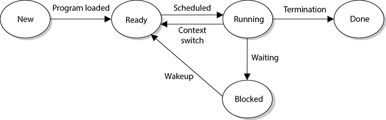
Figure 3-11 Processes enter and exit different states.
Is it really necessary to understand this stuff all the way down to the process level? Well, this is where everything actually takes place. All software works in “units” of processes. If you do not understand how processes work, you cannot understand how software works. If you do not understand how software works, you cannot know if it is working securely. So yes, you need to know this stuff at this level. Let’s keep going.
The operating system is responsible for creating new processes, assigning them resources, synchronizing their communication, and making sure nothing insecure is taking place. The operating system keeps a process table, which has one entry per process. The table contains each individual process’s state, stack pointer, memory allocation, program counter, and status of open files in use. The reason the operating system documents all of this status information is that the CPU needs all of it loaded into its registers when it needs to interact with, for example, process 1. When process 1’s CPU time slice is over, all of the current status information on process 1 is stored in the process table so that when its time slice is open again, all of this status information can be put back into the CPU registers. So, when it is process 2’s time with the CPU, its status information is transferred from the process table to the CPU registers and transferred back again when the time slice is over. These steps are shown in Figure 3-12.
How does a process know when it can communicate with the CPU? This is taken care of by using interrupts. An operating system fools us, and applications, into thinking it and the CPU are carrying out all tasks (operating system, applications, memory, I/O, and user activities) simultaneously. In fact, this is impossible. Most CPUs can do only one thing at a time. So the system has hardware and software interrupts. When a device needs to communicate with the CPU, it has to wait for its interrupt to be called upon. The same thing happens in software. Each process has an interrupt assigned to it. It is like pulling a number at a customer service department in a store. You can’t go up to the counter until your number has been called out.
When a process is interacting with the CPU and an interrupt takes place (another process has requested access to the CPU), the current process’s information is stored in the process table, and the next process gets its time to interact with the CPU.
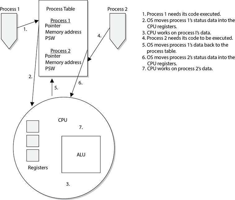
Figure 3-12 A process table contains process status data that the CPU requires.
NOTE Some critical processes cannot afford to have their functionality interrupted by another process. The operating system is responsible for setting the priorities for the different processes. When one process needs to interrupt another process, the operating system compares the priority levels of the two processes to determine if this interruption should be allowed.
There are two categories of interrupts: maskable and nonmaskable. A maskable interrupt is assigned to an event that may not be overly important, and the programmer can indicate that if that interrupt calls, the program does not stop what it is doing. This means the interrupt is ignored. A nonmaskable interrupt can never be overridden by an application because the event that has this type of interrupt assigned to it is critical. As an example, the reset button would be assigned a nonmaskable interrupt. This means that when this button is pushed, the CPU carries out its instructions right away.
As an analogy, a boss can tell her administrative assistant she is not going to take any calls unless the Pope or Elvis phones. This means all other people will be ignored or masked (maskable interrupt), but the Pope and Elvis will not be ignored (nonmaskable interrupt).
The watchdog timer is an example of a critical process that must always do its thing. This process will reset the system with a warm boot if the operating system hangs and cannot recover itself. For example, if there is a memory management problem and the operating system hangs, the watchdog timer will reset the system. This is one mechanism that ensures the software provides more of a stable environment.
Thread Management
As described earlier, a process is a program in memory. More precisely, a process is the program’s instructions and all the resources assigned to the process by the operating system. It is just easier to group all of these instructions and resources together and control them as one entity, which is a process. When a process needs to send something to the CPU for processing, it generates a thread. A thread is made up of an individual instruction set and the data that must be worked on by the CPU.
Most applications have several different functions. Word processing applications can open files, save files, open other programs (such as an e-mail client), and print documents. Each one of these functions requires a thread (instruction set) to be dynamically generated. So, for example, if Tom chooses to print his document, the word processing process generates a thread that contains the instructions of how this document should be printed (font, colors, text, margins, and so on). If he chooses to send a document via e-mail through this program, another thread is created that tells the e-mail client to open and what file needs to be sent. Threads are dynamically created and destroyed as needed. Once Tom is done printing his document, the thread that was generated for this functionality is broken down.
A program that has been developed to carry out several different tasks at one time (display, print, interact with other programs) is capable of running several different threads simultaneously. An application with this capability is referred to as a multithreaded application.
Each thread shares the same resources of the process that created it. So, all the threads created by a word processing application work in the same memory space and have access to all the same files and system resources. And how is this related to security? Software security ultimately comes down to what threads and processes are doing. If they are behaving properly, things work as planned and there are no issues to be concerned about. But if a thread misbehaves and it is working in a privileged mode, then it can carry out malicious activities that affect critical resources of the system. Attackers commonly inject code into a running process to carry out some type of compromise. Let’s think this through. When an operating system is preparing to load a process into memory, it goes through a type of criteria checklist to make sure the process is valid and will not negatively affect the system. Once the process passes this check, the process is loaded into memory and is assigned a specific operation mode (user or privileged). An attacker “injects” instructions into this running process, which means the process is his vehicle for destruction. Since the process has already gone through a security check before it was loaded into memory, it is trusted and has access to system resources. If an attacker can inject malicious instructions into this process, this trusted process carries out the attacker’s demands. These demands could be to collect data as the user types it in on her keyboard, steal passwords, send out malware, etc. If the process is running at a privileged mode, the attacker can carry out more damage because more critical system resources are available to him through this running process. When she creates her product, a software developer needs to make sure that running processes will not accept unqualified instructions and allow for these types of compromises. Processes should only accept instructions for an approved entity, and the instructions that it accepts should be validated before execution. It is like “stranger danger” with children. We teach our children to not take candy from a stranger, and in turn we need to make sure our software processes are not accepting improper instructions from an unknown source.
Process Scheduling
Scheduling and synchronizing various processes and their activities is part of process management, which is a responsibility of the operating system. Several components need to be considered during the development of an operating system, which will dictate how process scheduling will take place. A scheduling policy is created to govern how threads will interact with other threads. Different operating systems can use different schedulers, which are basically algorithms that control the timesharing of the CPU. As stated earlier, the different processes are assigned different priority levels (interrupts) that dictate which processes overrule other processes when CPU time allocation is required. The operating system creates and deletes processes as needed and oversees them changing state (ready, blocked, running). The operating system is also responsible for controlling deadlocks between processes attempting to use the same resources.
If a process scheduler is not built properly, an attacker could manipulate it. The attacker could ensure that certain processes do not get access to system resources (creating a denial-of-service attack) or that a malicious process has its privileges escalated (allowing for extensive damage). An operating system needs to be built in a secure manner to ensure that an attacker cannot slip in and take over control of the system’s processes.
When a process makes a request for a resource (memory allocation, printer, secondary storage devices, disk space, and so on), the operating system creates certain data structures and dedicates the necessary processes for the activity to be completed. Once the action takes place (a document is printed, a file is saved, or data is retrieved from the drive), the process needs to tear down these built structures and release the resources back to the resource pool so they are available for other processes. If this does not happen properly, the system may run out of critical resources—as in memory. Attackers have identified programming errors in operating systems that allow them to starve the system of its own memory. This means the attackers exploit a software vulnerability that ensures that processes do not properly release their memory resources. Memory is continually committed and not released and the system is depleted of this resource until it can no longer function. This is another example of a denial-of-service (DoS) attack.
Another situation to be concerned about is a software deadlock. One example of a deadlock situation is when process A commits resource 1 and needs to use resource 2 to properly complete its task, but process B has committed resource 2 and needs resource 1 to finish its job. Both processes are in deadlock because they do not have the resources they need to finish the function they are trying to carry out. This situation does not take place as often as it used to as a result of better programming. Also, operating systems now have the intelligence to detect this activity and either release committed resources or control the allocation of resources so they are properly shared between processes.
Operating systems have different methods of dealing with resource requests and releases and solving deadlock situations. In some systems, if a requested resource is unavailable for a certain period of time, the operating system kills the process that is “holding on to” that resource. This action releases the resource from the process that had committed it and restarts the process so it is “clean” and available for use by other applications. Other operating systems might require a program to request all the resources it needs before it actually starts executing instructions, or require a program to release its currently committed resources before it may acquire more.
Process Activity
Computers can run different applications and processes at the same time. The processes have to share resources and play nice with each other to ensure a stable and safe computing environment that maintains its integrity. Some memory, data files, and variables are actually shared between different processes. It is critical that more than one process does not attempt to read and write to these items at the same time. The operating system is the master program that prevents this type of action from taking place and ensures that programs do not corrupt each other’s data held in memory. The operating system works with the CPU to provide time slicing through the use of interrupts to ensure that processes are provided with adequate access to the CPU. This also makes certain that critical system functions are not negatively affected by rogue applications.
To protect processes from each other, operating systems commonly have functionality that implements process isolation. Process isolation is necessary to ensure that processes do not “step on each other’s toes,” communicate in an insecure manner, or negatively affect each other’s productivity. Older operating systems did not enforce process isolation as well as systems do today. This is why in earlier operating systems, when one of your programs hung, all other programs, and sometimes the operating system itself, hung. With process isolation, if one process hangs for some reason, it will not affect the other software running. (Process isolation is required for preemptive multitasking.) Different methods can be used to enforce process isolation:
• Encapsulation of objects
• Time multiplexing of shared resources
• Naming distinctions
• Virtual memory mapping
When a process is encapsulated, no other process understands or interacts with its internal programming code. When process A needs to communicate with process B, process A just needs to know how to communicate with process B’s interface. An interface defines how communication must take place between two processes. As an analogy, think back to how you had to communicate with your third-grade teacher. You had to call her Mrs. So-and-So, say please and thank you, and speak respectfully to get whatever it was you needed. The same thing is true for software components that need to communicate with each other. They must know how to communicate properly with each other’s interfaces. The interfaces dictate the type of requests a process will accept and the type of output that will be provided. So, two processes can communicate with each other, even if they are written in different programming languages, as long as they know how to communicate with each other’s interface. Encapsulation provides data hiding, which means that outside software components will not know how a process works and will not be able to manipulate the process’s internal code. This is an integrity mechanism and enforces modularity in programming code.
If a process is not isolated properly through encapsulation, this means its interface is accepting potentially malicious instructions. The interface is like a membrane filter that our cells within our bodies use. Our cells filter fluid and molecules that are attempting to enter them. If some type of toxin slips by the filter, we can get sick because the toxin has entered the worker bees of our bodies—cells. Processes are the worker bees of our software. If they accept malicious instructions, our systems can get sick.
Time multiplexing was already discussed, although we did not use this term. Time multiplexing is a technology that allows processes to use the same resources. As stated earlier, a CPU must be shared among many processes. Although it seems as though all applications are running (executing their instructions) simultaneously, the operating system is splitting up time shares between each process. Multiplexing means there are several data sources and the individual data pieces are piped into one communication channel. In this instance, the operating system is coordinating the different requests from the different processes and piping them through the one shared CPU. An operating system must provide proper time multiplexing (resource sharing) to ensure a stable working environment exists for software and users.
NOTE Today’s CPUs have multiple cores, meaning that they have multiple processors. This basically means that there are several smaller CPUs (processors) integrated into one larger CPU. So in reality the different processors on the CPU can execute instruction code simultaneously, making the computer overall much faster. The operating system has to multiplex process requests and “feed” them into the individual processors for instruction execution.
While time multiplexing and multitasking is a performance requirement of our systems today and is truly better than sliced bread, it introduces a lot of complexity to our systems. We are forcing our operating systems to not only do more things faster, we are forcing them to do all of these things simultaneously. As the complexity of our systems increases, the potential of truly securing them decreases. There is an inverse relationship between complexity and security: as one goes up, the other one usually goes down. But this fact does not necessarily predict doom and gloom; what it means is that software architecture and development has to be done in a more disciplined manner.
Naming distinctions just means that the different processes have their own name or identification value. Processes are usually assigned process identification (PID) values, which the operating system and other processes use to call upon them. If each process is isolated, that means each process has its own unique PID value. This is just another way to enforce process isolation.
Virtual address memory mapping is different from the physical addresses of memory. An application is written such that it basically “thinks” it is the only program running within an operating system. When an application needs memory to work with, it tells the operating system how much memory it needs. The operating system carves out that amount of memory and assigns it to the requesting application. The application uses its own address scheme, which usually starts at 0, but in reality, the application does not work in the physical address space it thinks it is working in. Rather, it works in the address space the operating system assigns to it. The physical memory is the RAM chips in the system. The operating system chops up this memory and assigns portions of it to the requesting processes. Once the process is assigned its own memory space, it can address this portion however it is written to do so. Virtual address mapping allows the different processes to have their own memory space; the operating system ensures no processes improperly interact with another process’s memory. This provides integrity and confidentiality for the individual processes and their data and an overall stable processing environment for the operating system.
If an operating system has a flaw in the programming code that controls memory mapping, an attacker could manipulate this function. Since everything within an operating system actually has to operate in memory to work, the ability to manipulate memory addressing can be very dangerous.
Memory Management
To provide a safe and stable environment, an operating system must exercise proper memory management—one of its most important tasks. After all, everything happens in memory.
The goals of memory management are to
• Provide an abstraction level for programmers
• Maximize performance with the limited amount of memory available
• Protect the operating system and applications loaded into memory
Abstraction means that the details of something are hidden. Developers of applications do not know the amount or type of memory that will be available in each and every system their code will be loaded on. If a developer had to be concerned with this type of detail, then her application would be able to work only on the one system that maps to all of her specifications. To allow for portability, the memory manager hides all of the memory issues and just provides the application with a memory segment. The application is able to run without having to know all the hairy details of the operating system and hardware it is running on.
Every computer has a memory hierarchy. Certain small amounts of memory are very fast and expensive (registers, cache), while larger amounts are slower and less expensive (RAM, hard drive). The portion of the operating system that keeps track of how these different types of memory are used is lovingly called the memory manager. Its jobs are to allocate and deallocate different memory segments, enforce access control to ensure processes are interacting only with their own memory segments, and swap memory contents from RAM to the hard drive.

The memory manager has five basic responsibilities:
Relocation:
• Swap contents from RAM to the hard drive as needed (explained later in the “Virtual Memory” section of this chapter)
• Provide pointers for applications if their instructions and memory segment have been moved to a different location in main memory
Protection:
• Limit processes to interact only with the memory segments assigned to them
• Provide access control to memory segments
Sharing:
• Use complex controls to ensure integrity and confidentiality when processes need to use the same shared memory segments
• Allow many users with different levels of access to interact with the same application running in one memory segment
Logical organization:
• Segment all memory types and provide an addressing scheme for each at an abstraction level
• Allow for the sharing of specific software modules, such as dynamic link library (DLL) procedures
Physical organization:
• Segment the physical memory space for application and operating system processes
NOTE A dynamic link library (DLL) is a set of functions that applications can call upon to carry out different types of procedures. For example, the Windows operating system has a crypt32.dll that is used by the operating system and applications for cryptographic functions. Windows has a set of DLLs, which is just a library of functions to be called upon, and crypt32.dll is just one example.
How can an operating system make sure a process only interacts with its memory segment? When a process creates a thread because it needs some instructions and data processed, the CPU uses two registers. A base register contains the beginning address that was assigned to the process, and a limit register contains the ending address, as illustrated in Figure 3-13. The thread contains an address of where the instruction and data reside that need to be processed. The CPU compares this address to the base and limit registers to make sure the thread is not trying to access a memory segment outside of its bounds. So, the base register makes it impossible for a thread to reference a memory address below its allocated memory segment, and the limit register makes it impossible for a thread to reference a memory address above this segment.
If an operating system has a memory manager that does not enforce the memory limits properly, an attacker can manipulate its functionality and use it against the system. There have been several instances over the years where attackers would do just this and bypass these types of controls. Architects and developers of operating systems have to think through these types of weaknesses and attack types to ensure that the system properly protects itself.

Figure 3-13 Base and limit registers are used to contain a process in its own memory segment.
Virtual Memory
Secondary storage is considered nonvolatile storage media and includes such things as the computer’s hard drive, USB drives, and optical discs. When RAM and secondary storage are combined, the result is virtual memory. The system uses hard drive space to extend its RAM memory space. Swap space is the reserved hard drive space used to extend RAM capabilities. Windows systems use the pagefile.sys file to reserve this space. When a system fills up its volatile memory space, it writes data from memory onto the hard drive. When a program requests access to this data, it is brought from the hard drive back into memory in specific units, called pages. This process is called virtual memory paging. Accessing data kept in pages on the hard drive takes more time than accessing data kept in RAM memory because physical disk read/write access must take place. Internal control blocks, maintained by the operating system, keep track of what page frames are residing in RAM and what is available “offline,” ready to be called into RAM for execution or processing, if needed. The payoff is that it seems as though the system can hold an incredible amount of information and program instructions in memory, as shown in Figure 3-14.
A security issue with using virtual swap space is that when the system is shut down or processes that were using the swap space are terminated, the pointers to the pages are reset to “available” even though the actual data written to disk is still physically there. This data could conceivably be compromised and captured. On various operating systems, there are routines to wipe the swap spaces after a process is done with it before it is used again. The routines should also erase this data before a system shutdown, at which time the operating system would no longer be able to maintain any control over what happens on the hard drive surface.

Figure 3-14 Combining RAM and secondary storage to create virtual memory
CAUTION If a program, file, or data is encrypted and saved on the hard drive, it will be decrypted when used by the controlling program. While this unencrypted data is sitting in RAM, the system could write out the data to the swap space on the hard drive in its unencrypted state. This is also true for secret and private keys being held in RAM. Attackers have figured out how to gain access to this space in unauthorized manners.
Input/Output Device Management
We have covered a lot of operating system responsibilities up to now, and we are not stopping yet. An operating system also has to control all input/output devices. It sends commands to them, accepts their interrupts when they need to communicate with the CPU, and provides an interface between the devices and the applications.
I/O devices are usually considered block or character devices. A block device works with data in fixed-size blocks, each block with its own unique address. A disk drive is an example of a block device. A character device, such as a printer, network interface card (NIC), or mouse, works with streams of characters, without using any fixed sizes. This type of data is not addressable.
When a user chooses to print a document, open a stored file on a hard drive, or save files to a USB drive, these requests go from the application the user is working in, through the operating system, to the device requested. The operating system uses a device driver to communicate with a device controller, which may be a circuit card that fits into an expansion slot on the motherboard. The controller is an electrical component with its own software that provides a communication path that enables the device and operating system to exchange data. The operating system sends commands to the device controller’s registers, and the controller then writes data to the peripheral device or extracts data to be processed by the CPU, depending on the given commands. If the command is to extract data from the hard drive, the controller takes the bits and puts them into the necessary block size and carries out a checksum activity to verify the integrity of the data. If the integrity is successfully verified, the data is put into memory for the CPU to interact with.
Interrupts
When an I/O device has completed whatever task was asked of it, it needs to inform the CPU that the necessary data is now in memory for processing. The device’s controller sends a signal down a bus, which is detected by the interrupt controller. (This is what it means to use an interrupt. The device signals the interrupt controller and is basically saying, “I am done and need attention now.”) If the CPU is busy and the device’s interrupt is not a higher priority than whatever job is being processed, then the device has to wait. The interrupt controller sends a message to the CPU, indicating what device needs attention. The operating system has a table (called the interrupt vector) of all the I/O devices connected to it. The CPU compares the received number with the values within the interrupt vector so it knows which I/O device needs its services. The table has the memory addresses of the different I/O devices. So when the CPU understands that the hard drive needs attention, it looks in the table to find the correct memory address. This is the new program counter value, which is the initial address of where the CPU should start reading from.
One of the main goals of the operating system software that controls I/O activity is to be device independent. This means a developer can write an application to read (open a file) or write (save a file) to any device (USB drive, hard drive, optical disc drive, etc.). This level of abstraction frees application developers from having to write different procedures to interact with the various I/O devices. If a developer had to write an individual procedure of how to write to an optical disc drive and how to write to a USB drive, how to write to a hard disk, and so on, each time a new type of I/O device was developed, all of the applications would have to be patched or upgraded.
Operating systems can carry out software I/O procedures in various ways. We will look at the following methods:
• Programmed I/O
• Interrupt-driven I/O
• I/O using DMA
• Premapped I/O
• Fully mapped I/O
Programmable I/O If an operating system is using programmable I/O, this means the CPU sends data to an I/O device and polls the device to see if it is ready to accept more data. If the device is not ready to accept more data, the CPU wastes time by waiting for the device to become ready. For example, the CPU would send a byte of data (a character) to the printer and then ask the printer if it is ready for another byte. The CPU sends the text to be printed 1 byte at a time. This is a very slow way of working and wastes precious CPU time. So the smart people figured out a better way: interrupt-driven I/O.
Interrupt-Driven I/O If an operating system is using interrupt-driven I/O, this means the CPU sends a character over to the printer and then goes and works on another process’s request. When the printer is done printing the first character, it sends an interrupt to the CPU. The CPU stops what it is doing, sends another character to the printer, and moves to another job. This process (send character—go do something else—interrupt—send another character) continues until the whole text is printed. Although the CPU is not waiting for each byte to be printed, this method does waste a lot of time dealing with all the interrupts. So we excused those smart people and brought in some new smarter people, who came up with I/O using DMA.
I/O Using DMA Direct memory access (DMA) is a way of transferring data between I/O devices and the system’s memory without using the CPU. This speeds up data transfer rates significantly. When used in I/O activities, the DMA controller feeds the characters to the printer without bothering the CPU. This method is sometimes referred to as unmapped I/O.
Premapped I/O Premapped I/O and fully mapped I/O (described next) do not pertain to performance, as do the earlier methods, but provide two approaches that can directly affect security. In a premapped I/O system, the CPU sends the physical memory address of the requesting process to the I/O device, and the I/O device is trusted enough to interact with the contents of memory directly, so the CPU does not control the interactions between the I/O device and memory. The operating system trusts the device to behave properly. Scary.
Fully Mapped I/O Under fully mapped I/O, the operating system does not trust the I/O device. The physical address is not given to the I/O device. Instead, the device works purely with logical addresses and works on behalf (under the security context) of the requesting process, so the operating system does not trust the device to interact with memory directly. The operating system does not trust the process or device, and it acts as the broker to control how they communicate with each other.
CPU Architecture Integration
An operating system and a CPU have to be compatible and share a similar architecture to work together. While an operating system is software and a CPU is hardware, they actually work so closely together when a computer is running that this delineation gets blurred. An operating system has to be able to “fit into” a CPU like a hand in a glove. Once a hand is inside of a glove, they both move together as a single entity.
An operating system and a CPU must be able to communicate through an instruction set. You may have heard of x86, which is a family of instruction sets. An instruction set is a language an operating system must be able to speak to properly communicate to a CPU. As an analogy, if you want Jimmy to carry out some tasks for you, you will have to tell him the instructions in a language that he understands.
The microarchitecture contains the things that make up the physical CPU (registers, logic gates, ALU, cache, etc.). The CPU knows mechanically how to use all of these parts; it just needs to know what the operating system wants it to do. A chef knows how to use all of his pots, pans, spices, and ingredients, but he needs an order from the menu so he knows how to use all of these properly to achieve the requested outcome. Similarly, the CPU has a “menu” of operations the operating system can “order” from, which is the instruction set. The operating system puts in its order (render graphics on screen, print to printer, encrypt data, etc.), and the CPU carries out the request and provides the result.
TIP The most common instruction set in use today (x86) can be used within different microarchitectures (Intel, AMD, etc.) and with different operating systems (Windows, macOS, Linux, etc.).
Along with sharing this same language (instruction set), the operating system and CPU have to work within the same ringed architecture. Let’s approach this from the top and work our way down. If an operating system is going to be stable, it must be able to protect itself from its users and their applications. This requires the capability to distinguish between operations performed on behalf of the operating system itself and operations performed on behalf of the users or applications. This can be complex because the operating system software may be accessing memory segments, sending instructions to the CPU for processing, accessing secondary storage devices, communicating with peripheral devices, dealing with networking requests, and more at the same time. Each user application (e-mail client, antimalware program, web browser, word processor, personal firewall, and so on) may also be attempting the same types of activities at the same time. The operating system must keep track of all of these events and ensure none of them puts the system at risk.
The operating system has several protection mechanisms to ensure processes do not negatively affect each other or the critical components of the system itself. One has already been mentioned: memory protection. Another security mechanism the system uses is a ring-based architecture.
The architecture of the CPU dictates how many rings are available for an operating system to use. As shown in Figure 3-15, the rings act as containers and barriers. They are containers in that they provide an execution environment for processes to be able to carry out their functions, and barriers in that the different processes are “walled off” from each other based upon the trust the operating system has in them.
Figure 3-15 More-trusted processes operate within lower-numbered rings.
Suppose you build a facility based upon this type of ring structure. Your crown jewels are stored in the center of the facility (ring 0), so you are not going to allow just anyone in this section of your building—only the people you really trust. You will allow the people you kind of trust in the next level of your facility (ring 1). If you don’t trust a particular person at all, you are going keep that person in ring 3 so that he is as far from your crown jewels as possible. This is how the ring structure of a CPU works. Ring 0 is for the most trusted components of the operating system itself. This is because processes that are allowed to work in ring 0 can access very critical components in the system. Ring 0 is where the operating system’s kernel (most trusted and powerful processes) works. Less trusted processes, as in operating system utilities, can work in ring 1, and the least trusted processes (applications) work in the farthest ring, ring 3. This layered approach provides a self-protection mechanism for the operating system.
Operating system components that operate in ring 0 have the most access to memory locations, peripheral devices, system drivers, and sensitive configuration parameters. Because this ring provides much more dangerous access to critical resources, it is the most protected. Applications usually operate in ring 3, which limits the type of memory, peripheral device, and driver access activity and is controlled through the operating system services and system calls. The type of commands and instructions sent to the CPU from applications in the outer rings are more restrictive in nature. If an application tries to send instructions to the CPU that fall outside its permission level, the CPU treats this violation as an exception and may show a general protection fault or exception error and attempt to shut down the offending application.
These protection rings provide an intermediate layer between processes and are used for access control when one process tries to access another process or interact with system resources. The ring number determines the access level a process has—the lower the ring number, the greater the amount of privilege given to the process running within that ring. A process in ring 3 cannot directly access a process in ring 1, but processes in ring 1 can directly access processes in ring 3. Entities cannot directly communicate with objects in higher rings.
If we go back to our facility analogy, people in ring 0 can go and talk to any of the other people in the different areas (rings) of the facility. You trust them and you will let them do what they need to do. But if people in ring 3 of your facility want to talk to people in ring 2, you cannot allow this to happen in an unprotected manner. You don’t trust these people and do not know what they will do. Someone from ring 3 might try to punch someone from ring 2 in the face and then everyone will be unhappy. So if someone in ring 3 needs to communicate to someone in ring 2, she has to write down her message on a piece of paper and give it to the guard. The guard will review it and hand it to the person in ring 2 if it is safe and acceptable.
In an operating system, the less trusted processes that are working in ring 3 send their communication requests to an API provided by the operating system specifically for this purpose (guard). The communication request is passed to the more trusted process in ring 2 in a controlled and safe manner.
CPU Operation Modes
As stated earlier, the CPU provides the ring structure architecture, and the operating system assigns its processes to the different rings. When a process is placed in ring 0, its activities are carried out in kernel mode, which means it can access the most critical resources in a nonrestrictive manner. The process is assigned a status level by the operating system (stored as PSW), and when the process needs to interact with the CPU, the CPU checks its status to know what it can and cannot allow the process to do. If the process has the status of user mode, the CPU will limit the process’s access to system resources and restrict the functions it can carry out on these resources.
Attackers have found many ways around this protection scheme and have tricked operating systems into loading their malicious code into ring 0, which is very dangerous. Attackers have fooled operating systems by creating their malicious code to mimic system-based DLLs, loadable kernel modules, or other critical files. The operating system then loads the malicious code into ring 0, and it runs in kernel mode. At this point the code could carry out almost any activity within the operating system in an unprotected manner. The malicious code can install key loggers, sniffers, code injection tools, and Trojaned files. The code could delete files on the hard drive, install back doors, or send sensitive data to the attacker’s computer using the compromised system’s network protocol stack.
NOTE The actual ring numbers available in a CPU architecture are dictated by the CPU itself. Some processors provide four rings and some provide eight or more. The operating systems do not have to use each available ring in the architecture; for example, Windows, macOS, and most versions of Linux commonly use only rings 0 and 3 and do not use ring 1 or ring 2. The vendor of the CPU determines the number of available rings, and the vendor of the operating system determines how it will use these rings.
Operating System Architectures
We started this chapter by looking at system architecture approaches. Remember that a system is made up of all the necessary pieces for computation: hardware, firmware, and software components. We then moved into the architecture of a CPU, looking only at the processor. Now we will look at operating system architectures, which deal specifically with the software components of a system.
Operating system architectures have gone through quite an evolutionary process based upon industry functionality and security needs. The architecture is the framework that dictates how the pieces and parts of the operating system interact with each other and provide the functionality that the applications and users require of it. This section looks at the monolithic, layered, microkernel, and hybrid microkernel architectures.
While operating systems are very complex, some main differences in the architectural approaches have come down to what is running in kernel mode and what is not. In a monolithic architecture, all of the operating system processes work in kernel mode, as illustrated in Figure 3-16. The services provided by the operating system (memory management, I/O management, process scheduling, file management, etc.) are available to applications through system calls.
Figure 3-16 Monolithic operating system architecture
Earlier operating systems, such as MS-DOS, were based upon a monolithic design. The whole operating system acted as one software layer between the user applications and the hardware level. There are several problems with this approach: complexity, portability, extensibility, and security. Since the functionality of the code is spread throughout the system, it is hard to test and debug. If there is a flaw in a software component, it is difficult to localize and easily fix. Many pieces of this spaghetti bowl of code had to be modified just to address one issue.
This type of operating system is also hard to port from one hardware platform to another because the hardware interfaces are implemented throughout the software. If the operating system has to work on new hardware, extensive rewriting of the code is required. Too many components interact directly with the hardware, which increased the complexity.
Since the monolithic system is not modular in nature, it is difficult to add and subtract functionality. As we will see in this section, later operating systems became more modular in nature to allow for functionality to be added as needed. And since all the code ran in a privileged state (kernel mode), user mistakes could cause drastic effects and malicious activities could take place more easily.
In the next generation of operating system architecture, system architects add more organization to the system. The layered operating system architecture separates system functionality into hierarchical layers. For example, a system that followed a layered architecture was, strangely enough, called THE (Technische Hogeschool Eindhoven) multiprogramming system. THE had five layers of functionality. Layer 0 controlled access to the processor and provided multiprogramming functionality, layer 1 carried out memory management, layer 2 provided interprocess communication, layer 3 dealt with I/O devices, and layer 4 was where the applications resided. The processes at the different layers each had interfaces to be used by processes in layers below and above them.
This layered approach, illustrated in Figure 3-17, had the full operating system still working in kernel mode (ring 0). The main difference between the monolithic approach and this layered approach is that the functionality within the operating system was laid out in distinctive layers that called upon each other.
In the monolithic architecture, software modules communicate to each other in an ad hoc manner. In the layered architecture, module communication takes place in an organized, hierarchical structure. Routines in one layer only facilitate the layer directly below it, so no layer is missed.
Layered operating systems provide data hiding, which means that instructions and data (packaged up as procedures) at the various layers do not have direct access to the instructions and data at any other layers. Each procedure at each layer has access only to its own data and a set of functions that it requires to carry out its own tasks. Allowing a procedure to access more procedures than it really needs opens the door for more successful compromises. For example, if an attacker is able to compromise and gain control of one procedure and this procedure has direct access to all other procedures, the attacker could compromise a more privileged procedure and carry out more devastating activities.
A monolithic operating system provides only one layer of security. In a layered system, each layer should provide its own security and access control. If one layer contains the necessary security mechanisms to make security decisions for all the other layers, then that one layer knows too much about (and has access to) too many objects at the different layers. This directly violates the data-hiding concept. Modularizing software and its code increases the assurance level of the system because if one module is compromised, it does not mean all other modules are now vulnerable.
Figure 3-17 Layered operating system architecture
Since this layered approach provides more modularity, it allows for functionality to be added to and subtracted from the operating systems more easily. (You experience this type of modularity when you load new kernel modules into Linux-based systems or DLLs in Windows.) The layered approach also introduces the idea of having an abstraction level added to the lower portion of the operating system. This abstraction level allows the operating system to be more portable from one hardware platform to the next. (In Windows environments you know this invention as the Hardware Abstraction Layer, or HAL). Examples of layered operating systems are THE, VAX/VMS, Multics, and Unix (although THE and Multics are no longer in use).
The downfalls with this layered approach are performance, complexity, and security. If several layers of execution have to take place for even simple operating system activities, there can be a performance hit. The security issues mainly deal with so much code still running in kernel mode. The more processes that are running in a privileged state, the higher the likelihood of compromises that have high impact. The attack surface of the operating system overall needs to be reduced.
As the evolution of operating system development marches forward, the system architects reduce the number of required processes that made up the kernel (critical operating system components) and some operating system types move from a monolithic model to a microkernel model. The microkernel is a smaller subset of critical kernel processes, which focus mainly on memory management and interprocess communication, as shown in Figure 3-18. Other operating system components, such as protocols, device drivers, and file systems, are not included in the microkernel and work in user mode. The goal is to limit the processes that run in kernel mode so that the overall system is more secure, complexity is reduced, and portability of the operating system is increased.
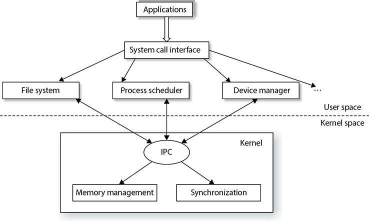
Figure 3-18 Microkernel architecture
Operating system vendors found that having just a stripped-down microkernel working in kernel mode had a lot of performance issues because processing required so many mode transitions. A mode transition takes place every time a CPU has to move between executing instructions for processes that work in kernel mode versus user mode. As an analogy, suppose you have to set up a different office environment for two employees, Sam and Vicky, when they come to the office to work. There is only one office with one desk, one computer, and one file cabinet (just like the computer only has one CPU). Before Sam gets to the office you have to put out the papers for his accounts, fill the file cabinet with files relating to his tasks, configure the workstation with his user profile, and make sure his coffee cup is available. When Sam leaves and before Vicky gets to the office, you have to change out all the papers, files, user profile, and coffee cup. Your responsibility is to provide the different employees with the right environment so that they can get right down to work when they arrive at the office, but constantly changing out all the items is time consuming. In essence, this is what a CPU has to do when an interrupt takes place and a process from a different mode (kernel or user) needs its instructions executed. The current process information has to be stored and saved so the CPU can come back and complete the original process’s requests. The new process information (memory addresses, program counter value, PSW, etc.) has to be moved into the CPU registers. Once this is completed, then the CPU can start executing the process’s instruction set. This back and forth has to happen because it is a multitasking system that is sharing one resource—the CPU.
So the industry went from a bloated kernel (whole operating system) to a small kernel (microkernel), but the performance hit was too great. There has to be a compromise between the two, which is referred to as the hybrid microkernel architecture.
In a hybrid microkernel architecture, the microkernel still exists and carries out mainly interprocess communication and memory management responsibilities. All of the other operating services work in a clientserver model. The operating system services are the servers, and the application processes are the clients. When a user’s application needs the operating system to carry out some type of functionality for it (file system interaction, peripheral device communication, network access, etc.), it makes a request to the specific API of the system’s server service. This operating system service carries out the activity for the application and returns the result when finished. The separation of a microkernel and the other operating system services within a hybrid microkernel architecture is illustrated in Figure 3-19, which is the basic structure of a Windows environment. The services that run outside the microkernel are collectively referred to as the executive services.

Figure 3-19 Windows hybrid microkernel architecture
The basic core definitions of the different architecture types are as follows:
• Monolithic All operating system processes run in kernel mode.
• Layered All operating system processes run in a hierarchical model in kernel mode.
• Microkernel Core operating system processes run in kernel mode and the remaining ones run in user mode.
• Hybrid microkernel All operating system processes run in kernel mode. Core processes run within a microkernel and others run in a clientserver model.
The main architectures that are used in systems today are illustrated in Figure 3-20.
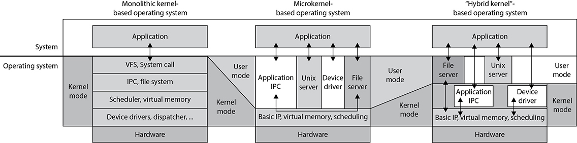
Figure 3-20 Major operating system kernel architectures
Operating system architecture is critical when it comes to the security of a system overall. Systems can be patched, but this is only a Band-Aid approach. Security should be baked in from the beginning and then thought through in every step of the development life cycle.
Virtual Machines
If you have been into computers for a while, you might remember computer games that did not have the complex, lifelike graphics of today’s games. Pong and Asteroids were what we had to play with when we were younger. In those simpler times, the games were 16-bit and were written to work in a 16-bit MS-DOS environment. When our Windows operating systems moved from 16-bit to 32-bit, the 32-bit operating systems were written to be backward compatible, so someone could still load and play a 16-bit game in an environment that the game did not understand. The continuation of this little life pleasure was available to users because the operating systems created virtual environments for the games to run in. Backward compatibility was also introduced with 64-bit operating systems.
When a 32-bit application needs to interact with a 64-bit operating system, it has been developed to make system calls and interact with the computer’s memory in a way that would only work within a 32-bit operating system—not a 64-bit system. So, the virtual environment simulates a 32-bit operating system, and when the application makes a request, the operating system converts the 32-bit request into a 64-bit request (this is called thunking) and reacts to the request appropriately. When the system sends a reply to this request, it changes the 64-bit reply into a 32-bit reply so the application understands it.
Today, virtual environments are much more advanced. Basic virtualization enables single hardware equipment to run multiple operating system environments simultaneously, greatly enhancing processing power utilization, among other benefits. Creating virtual instances of operating systems, applications, and storage devices is known as virtualization.
In today’s jargon, a virtual instance of an operating system is known as a virtual machine. A virtual machine is commonly referred to as a guest that is executed in the host environment. Virtualization allows a single host environment to execute multiple guests at once, with multiple virtual machines dynamically pooling resources from a common physical system. Computer resources such as RAM, processors, and storage are emulated through the host environment. The virtual machines do not directly access these resources; instead, they communicate with a hypervisor within the host environment, which is responsible for managing system resources. The hypervisor is the central program that controls the execution of the various guest operating systems and provides the abstraction level between the guest and host environments, as shown in Figure 3-21.
What this means is that you can have one computer running several different operating systems at one time. For example, you can run a system with Windows 10, Linux, and Windows 2016 on one computer. Think of a house that has different rooms. Each operating system gets its own room, but each shares the same resources that the house provides—a foundation, electricity, water, roof, and so on. An operating system that is “living” in a specific room does not need to know about or interact with another operating system in another room to take advantage of the resources provided by the house. The same concept happens in a computer: Each operating system shares the resources provided by the physical system (as in memory, processor, buses, and so on). They “live” and work in their own “rooms,” which are the guest virtual machines. The physical computer itself is the host.
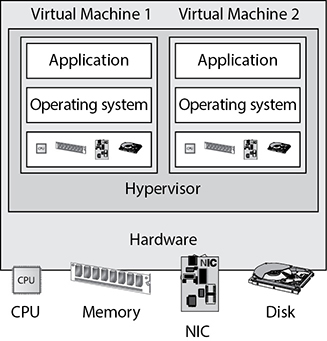
Figure 3-21 The hypervisor controls virtual machine instances.
Why do this? One reason is that it is cheaper than having a full physical system for each and every operating system. If they can all live on one system and share the same physical resources, your costs are reduced immensely. This is the same reason people get roommates. The rent can be split among different people, and all can share the same house and resources. Another reason to use virtualization is security. Providing software their own “clean” environments to work within reduces the possibility of them negatively interacting with each other.
The following useful list, from “An Introduction to Virtualization” by Amit Singh (available at www.kernelthread.com/publications/virtualization), pertains to the different reasons for using virtualization in various environments. It was written years ago (2004), but is still very applicable to today’s needs and the CISSP exam.
• Virtual machines can be used to consolidate the workloads of several under-utilized servers to fewer machines, perhaps a single machine (server consolidation). Related benefits (perceived or real, but often cited by vendors) are savings on hardware, environmental costs, management, and administration of the server infrastructure.
• The need to run legacy applications is served well by virtual machines. A legacy application might simply not run on newer hardware and/or operating systems. Even if it does, if may under-utilize the server, so as above, it makes sense to consolidate several applications. This may be difficult without virtualization as such applications are usually not written to co-exist within a single execution environment.
• Virtual machines can be used to provide secure, isolated sandboxes for running untrusted applications. You could even create such an execution environment dynamically—on the fly—as you download something from the Internet and run it. Virtualization is an important concept in building secure computing platforms.
• Virtual machines can be used to create operating systems, or execution environments with resource limits, and given the right schedulers, resource guarantees. Partitioning usually goes hand-in-hand with quality of service in the creation of QoS-enabled operating systems.
• Virtual machines can provide the illusion of hardware, or hardware configuration that you do not have (such as SCSI devices, multiple processors, …). Virtualization can also be used to simulate networks of independent computers.
• Virtual machines can be used to run multiple operating systems simultaneously: different versions, or even entirely different systems, which can be on hot standby. Some such systems may be hard or impossible to run on newer real hardware.
• Virtual machines allow for powerful debugging and performance monitoring. You can put such tools in the virtual machine monitor, for example. Operating systems can be debugged without losing productivity, or setting up more complicated debugging scenarios.
• Virtual machines can isolate what they run, so they provide fault and error containment. You can inject faults proactively into software to study its subsequent behavior.
• Virtual machines make software easier to migrate, thus aiding application and system mobility.
• You can treat application suites as appliances by “packaging” and running each in a virtual machine.
• Virtual machines are great tools for research and academic experiments. Since they provide isolation, they are safer to work with. They encapsulate the entire state of a running system: you can save the state, examine it, modify it, reload it, and so on. The state also provides an abstraction of the workload being run.
• Virtualization can enable existing operating systems to run on shared memory multiprocessors.
• Virtual machines can be used to create arbitrary test scenarios, and can lead to some very imaginative, effective quality assurance.
• Virtualization can be used to retrofit new features in existing operating systems without “too much” work.
• Virtualization can make tasks such as system migration, backup, and recovery easier and more manageable.
• Virtualization can be an effective means of providing binary compatibility.
• Virtualization on commodity hardware has been popular in co-located hosting. Many of the above benefits make such hosting secure, cost-effective, and appealing in general.
• Virtualization is fun.
It is probably helpful to take a moment to think about what it means to be “engineering” something. Engineering is the deliberate application of science and math to building and maintaining something. There are a bunch of engineering methodologies, but they all share some basic ingredients. They all start by identifying some problem (that may very well be the end result of having engineered something previously) and figuring out a way to solve it. This solution is formally documented in a design, which is then built. Once the thing is built, it is tested to ensure it solves the problem, but also to see if it creates any new problems that need fixing. The process continues like this until we run out of time, money, or problems.
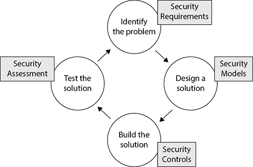
Security needs to be instilled in each step of the engineering process, even if we are building something that is not an obvious security product. Even as we define the problem we’re trying to solve, we start thinking of its security connotations and start thinking of security requirements for the product. As we design it, we apply the right security models to its design and ensure we build the right controls into it to satisfy the security requirements. Next, as we test the product to see how well it solves the problem, we also assess its security. As you can see, secure engineering means putting security into every phase of the engineering process.
System Security Architecture
Up to this point we have looked at system architectures, CPU architectures, and operating system architectures. Remember that a system architecture has several views to it, depending upon the stakeholder’s individual concerns. Since our main concern is security, we are going to approach system architecture from a security point of view and drill down into the core components that are part of most computing systems today. But first we need to understand how the goals for the individual system security architectures are defined.
Security Policy
In life we set goals for ourselves, our teams, companies, and families to meet. Setting a goal defines the desired end state. We might define a goal for our company to make $2 million by the end of the year. We might define a goal of obtaining three government contracts for our company within the next six months. A goal could be that we lose 30 pounds in 12 months or save enough money for our child to be able to go off to college when she turns 18 years old. The point is that we have to define a desired end state and from there we can lay out a structured plan on how to accomplish those goals, punctuated with specific action items and a defined time line.
It is not usually helpful to have vague goal statements, as in “save money” or “lose weight” or “become successful.” Our goals need to be specific, or how do we know when we accomplish them? This is also true in computer security. If your boss were to give you a piece of paper that had a simple goal written on it, “Build a secure system,” where would you start? What is the definition of a “system”? What is the definition of “secure”? You’d have no way of knowing whether you accomplished the goal. Now if your boss were to hand you the same paper with the following list included, you’d be in business:
• Discretionary access control–based operating system
• Provides role-based access control functionality
• Capability of protecting data classified at “public” and “confidential” levels
• Does not allow unauthorized access to sensitive data or critical system functions
• Enforces least privilege and separation of duties
• Provides auditing capabilities
• Implements trusted paths and trusted shells for sensitive processing activities
• Enforces identification, authentication, and authorization of trusted subjects
• Implements a capability-based authentication methodology
• Does not contain covert channels
• Enforces integrity rules on critical files
Now you have more direction on what it is that your boss wants you to accomplish, and you can work with your boss to form the overall security goals for the system you will be designing and developing. All of these goals need to be captured and outlined in a security policy.
Security starts at a policy level, with high-level directives that provide the foundational goals for a system overall and the components that make it up from a security perspective. A security policy is a strategic tool that dictates how sensitive information and resources are to be managed and protected. A security policy expresses exactly what the security level should be by setting the goals of what the security mechanisms are supposed to accomplish. This is an important element that has a major role in defining the architecture and design of the system. The security policy is a foundation for the specifications of a system and provides the baseline for evaluating a system after it is built. The evaluation is carried out to make sure that the goals that were laid out in the security policy were accomplished.
Security Architecture Requirements
In the 1970s computer systems were moving from single-user, stand-alone, centralized, and closed systems to multiuser systems that had multiprogramming functionality and networking capabilities. The U.S. government needed to ensure that all of the systems that it was purchasing and implementing were properly protecting its most secret secrets. The government had various levels of classified data (secret, top secret) and users with different clearance levels (Secret, Top Secret). It needed to come up with a way to instruct vendors on how to build computer systems to meet their security needs and in turn a way to test the products these vendors developed based upon those same security needs.
In 1972, the U.S. government released a report (“Computer Security Technology Planning Study”) that outlined basic and foundational security requirements of computer systems that it would deem acceptable for purchase and deployment. These requirements were further defined and built upon, which resulted in the Trusted Computer System Evaluation Criteria, which shaped the security architecture of almost all of the systems in use today. Some of the core tenets of these requirements were the trusted computing base, security perimeter, reference monitor, and security kernel.
Trusted Computing Base
The trusted computing base (TCB) is a collection of all the hardware, software, and firmware components within a system that provides some type of security and enforces the system’s security policy. The TCB does not address only operating system components, because a computer system is not made up of only an operating system. Hardware, software components, and firmware components can affect the system in a negative or positive manner, and each has a responsibility to support and enforce the security policy of that particular system. Some components and mechanisms have direct responsibilities in supporting the security policy, such as firmware that will not let a user boot a computer from a USB drive, or the memory manager that will not let processes overwrite other processes’ data. Then there are components that do not enforce the security policy but must behave properly and not violate the trust of a system. Examples of the ways in which a component could violate the system’s security policy include an application that is allowed to make a direct call to a piece of hardware instead of using the proper system calls through the operating system, a process that is allowed to read data outside of its approved memory space, or a piece of software that does not properly release resources after use.
The operating system’s kernel is made up of hardware, software, and firmware, so in a sense the kernel is the TCB. But the TCB can include other components, such as trusted commands, programs, and configuration files that can directly interact with the kernel. For example, when installing a Unix system, the administrator can choose to install the TCB configuration during the setup procedure. If the TCB is enabled, then the system has a trusted path, a trusted shell, and system integrity–checking capabilities. A trusted path is a communication channel between the user, or program, and the TCB. The TCB provides protection resources to ensure this channel cannot be compromised in any way. A trusted shell means that someone who is working in that shell (command interpreter) cannot “bust out of it” and other processes cannot “bust into it.”
Every operating system has specific components that would cause the system grave danger if they were compromised. The components that make up the TCB provide extra layers of protection around these mechanisms to help ensure they are not compromised, so the system will always run in a safe and predictable manner. While the TCB components can provide extra layers of protection for sensitive processes, they themselves have to be developed securely. The BIOS function should have a password protection capability and be tamperproof. The subsystem within a Windows operating system that generates access tokens should not be able to be hijacked and be used to produce fake tokens for malicious processes. Before a process can interact with a system configuration file, it must be authenticated by the security kernel. Device drivers should not be able to be modified in an unauthorized manner. Basically, any piece of a system that could be used to compromise the system or put it into an unstable condition is considered to be part of the TCB, and it must be developed and controlled very securely.
You can think of the TCB as a building. You want the building to be strong and safe, so there are certain components that absolutely have to be built and installed properly. The right types of construction nails need to be used, not the flimsy ones we use at home to hold up pictures of our grandparents. The beams in the walls need to be made out of steel and properly placed. The concrete in the foundation needs to be made of the right concentration of gravel and water. The windows need to be shatterproof. The electrical wiring needs to be of proper grade and grounded.
An operating system also has critical pieces that absolutely have to be built and installed properly. The memory manager has to be tamperproof and properly protect shared memory spaces. When working in kernel mode, the CPU must have all logic gates in the proper place. Operating system APIs must only accept secure service requests. Access control lists on objects cannot be modified in an unauthorized manner. Auditing must take place, and the audit trails cannot be modified in an unauthorized manner. Interprocess communication must take place in an approved and controlled manner.
The processes within the TCB are the components that protect the system overall. So the developers of the operating system must make sure these processes have their own execution domain. This means they reside in ring 0, their instructions are executed in privileged state, and no less trusted processes can directly interact with them. The developers need to ensure the operating system maintains an isolated execution domain, so their processes cannot be compromised or tampered with. The resources that the TCB processes use must also be isolated, so tight access control can be provided and all access requests and operations can be properly audited. So basically, the operating system ensures that all the non-TCB processes and TCB processes interact in a secure manner.
When a system goes through an evaluation process, part of the process is to identify the architecture, security services, and assurance mechanisms that make up the TCB. During the evaluation process, the tests must show how the TCB is protected from accidental or intentional tampering and compromising activity. For systems to achieve a higher trust level rating, they must meet well-defined TCB requirements, and the details of their operational states, development stages, testing procedures, and documentation will be reviewed with more granularity than systems attempting to achieve a lower trust rating.
Security Perimeter
As stated previously, not every process and resource falls within the TCB, so some of these components fall outside of an imaginary boundary referred to as the security perimeter. A security perimeter is a boundary that divides the trusted from the untrusted. For the system to stay in a secure and trusted state, precise communication standards must be developed to ensure that when a component within the TCB needs to communicate with a component outside the TCB, the communication cannot expose the system to unexpected security compromises. This type of communication is handled and controlled through interfaces.
For example, a resource that is within the boundary of the security perimeter is considered to be a part of the TCB and must not allow less trusted components access to critical system resources in an insecure manner. The processes within the TCB must also be careful about the commands and information they accept from less trusted resources. These limitations and restrictions are built into the interfaces that permit this type of communication to take place and are the mechanisms that enforce the security perimeter. Communication between trusted components and untrusted components needs to be controlled to ensure that the system stays stable and safe.
Recall that when we covered CPU architectures, we went through the various rings a CPU provides. The operating system places its software components within those rings. The most trusted components would go inside ring 0, and the less trusted components would go into the other rings. Strict and controlled communication has to be put into place to make sure a less trusted component does not compromise a more trusted component. This control happens through APIs. The APIs are like bouncers at bars. The bouncers only allow individuals who are safe into the bar environment and keep the others out. This is the same idea of a security perimeter. Strict interfaces need to be put into place to control the communication between the items within and outside the TCB.
TIP The TCB and security perimeter are not physical entities, but conceptual constructs used by system architects and developers to delineate between trusted and untrusted components and how they communicate.
Reference Monitor
Up to this point we have a CPU that provides a ringed structure and an operating system that places its components in the different rings based upon the trust level of each component. We have a defined security policy, which outlines the level of security we want our system to provide. We have chosen the mechanisms that will enforce the security policy (TCB) and implemented security perimeters (interfaces) to make sure these mechanisms communicate securely. Now we need to develop and implement a mechanism that ensures that the subjects that access objects within the operating system have been given the necessary permissions to do so. This means we need to develop and implement a reference monitor.
The reference monitor is an abstract machine that mediates all access subjects have to objects, both to ensure that the subjects have the necessary access rights and to protect the objects from unauthorized access and destructive modification. For a system to achieve a higher level of trust, it must require subjects (programs, users, processes) to be fully authorized prior to accessing an object (file, program, resource). A subject must not be allowed to use a requested resource until the subject has proven it has been granted access privileges to use the requested object. The reference monitor is an access control concept, not an actual physical component, which is why it is normally referred to as the “reference monitor concept” or an “abstract machine.”
The reference monitor defines the design requirements a reference validation mechanism must meet so that it can properly enforce the specifications of a system-based access control policy. Access control is made up of rules, which specify what subjects (processes, programs, users, etc.) can communicate with which objects (files, processes, peripheral devices, etc.) and what operations can be performed (read, write, execute, etc.). If you think about it, almost everything that takes place within an operating system is made up of subject-to-object communication and it has to be tightly controlled, or the whole system could be put at risk. If the access rules of the reference monitor are not properly enforced, a process could potentially misuse an object, which could result in corruption or compromise.
The reference monitor provides direction on how all access control decisions should be made and controlled in a central, concerted manner within a system. Instead of having distributed components carrying out subject-to-object access decisions individually and independently, all access decisions should be made by a core-trusted, tamperproof component of the operating system that works within the system’s kernel, which is the role of the security kernel.
Security Kernel
The security kernel is made up of hardware, software, and firmware components that fall within the TCB, and it implements and enforces the reference monitor concept. The security kernel mediates all access and functions between subjects and objects. The security kernel is the core of the TCB and is the most commonly used approach to building trusted computing systems. The security kernel has three main requirements:
• It must provide isolation for the processes carrying out the reference monitor concept, and the processes must be tamperproof.
• It must be invoked for every access attempt and must be impossible to circumvent. Thus, the security kernel must be implemented in a complete and foolproof way.
• It must be small enough to be tested and verified in a complete and comprehensive manner.
These are the requirements of the reference monitor; therefore, they are the requirements of the components that provide and enforce the reference monitor concept—the security kernel.
These issues work in the abstract but are implemented in the physical world of hardware devices and software code. The assurance that the components are enforcing the abstract idea of the reference monitor is proved through testing and evaluations.
EXAM TIP The reference monitor is a concept in which an abstract machine mediates all access to objects by subjects. The security kernel is the hardware, firmware, and software of the TCB that implements this concept. The TCB is the totality of protection mechanisms within a computer system that work together to enforce a security policy. It contains the security kernel and all other security protection mechanisms.
The following is a quick analogy to show you the relationship between the processes that make up the security kernel, the security kernel itself, and the reference monitor concept. Individuals (processes) make up a society (security kernel). For a society to have a certain standard of living, its members must interact in specific ways, which is why we have laws. The laws represent the reference monitor, which enforces proper activity. Each individual is expected to stay within the bounds of the laws and act in specific ways so society as a whole is not adversely affected and the standard of living is not threatened. The components within a system must stay within the bounds of the reference monitor’s laws so they will not adversely affect other components and threaten the security of the system.
For a system to provide an acceptable level of trust, it must be based on an architecture that provides the capabilities to protect itself from untrusted processes, intentional or accidental compromises, and attacks at different layers of the system. A majority of the trust ratings obtained through formal evaluations require a defined subset of subjects and objects, explicit domains, and the isolation of processes so their access can be controlled and the activities performed on them can be audited.
Let’s regroup. We know that a system’s trust is defined by how it enforces its own security policy. When a system is tested against specific criteria, a rating is assigned to the system and this rating is used by customers, vendors, and the computing society as a whole. The criteria will determine if the security policy is being properly supported and enforced. The security policy lays out the rules and practices pertaining to how a system will manage, protect, and allow access to sensitive resources. The reference monitor is a concept that says all subjects must have proper authorization to access objects, and this concept is implemented by the security kernel. The security kernel comprises all the resources that supervise system activity in accordance with the system’s security policy and is part of the operating system that controls access to system resources. For the security kernel to work correctly, the individual processes must be isolated from each other and domains must be defined to dictate which objects are available to which subjects.
NOTE Security policies that prevent information from flowing from a high security level to a lower security level are called multilevel security policies. These types of policies permit a subject to access an object only if the subject’s security level is higher than or equal to the object’s classification.
As previously stated, many of the concepts covered in the previous sections are abstract ideas that will be manifested in physical hardware components, firmware, software code, and activities through designing, building, and implementing a system. Operating systems implement access rights, permissions, access tokens, mandatory integrity levels, access control lists, access control entities, memory protection, sandboxes, virtualization, and more to meet the requirements of these abstract concepts.
Security Models
A security model maps the abstract goals of the policy to information system terms by specifying explicit data structures and techniques necessary to enforce the security policy. A security model is usually represented in mathematics and analytical ideas, which are mapped to system specifications and then developed by programmers through programming code. So we have a policy that encompasses security goals, such as “each subject must be authenticated and authorized before accessing an object.” The security model takes this requirement and provides the necessary mathematical formulas, relationships, and logic structure to be followed to accomplish this goal. From there, specifications are developed per operating system type (Unix, Windows, macOS, and so on), and individual vendors can decide how they are going to implement mechanisms that meet these necessary specifications.
A security policy outlines goals without regard to how they will be accomplished. A model is a framework that gives the policy form and solves security access problems for particular situations. Several security models have been developed to enforce security policies. The following sections provide overviews of the models with which you must be familiar as a CISSP.
Bell-LaPadula Model
The Bell-LaPadula model enforces the confidentiality aspects of access control. It was developed in the 1970s to prevent secret information from being accessed in an unauthorized manner. It was the first mathematical model of a multilevel security policy used to define the concept of secure modes of access and outlined rules of access. Its development was funded by the U.S. government to provide a framework for computer systems that would be used to store and process sensitive information. A system that employs the Bell-LaPadula model is called a multilevel security system because users with different clearances use the system, and the system processes data at different classification levels.
EXAM TIP The Bell-LaPadula model was developed to make sure secrets stay secret; thus, it provides and addresses confidentiality only. This model does not address the integrity of the data the system maintains—only who can and cannot access the data and what operations can be carried out.
Three main rules are used and enforced in the Bell-LaPadula model:
• Simple security rule
• *-property (star property) rule
• Strong star property rule
The simple security rule states that a subject at a given security level cannot read data that resides at a higher security level. For example, if Bob is given the security clearance of secret, this rule states he cannot read data classified as top secret. If the organization wanted Bob to be able to read top-secret data, it would have given him that clearance in the first place.
The *-property rule (star property rule) states that a subject in a given security level cannot write information to a lower security level. The simple security rule is referred to as the “no read up” rule, and the *-property rule is referred to as the “no write down” rule.
The strong star property rule states that a subject who has read and write capabilities can only perform both of those functions at the same security level; nothing higher and nothing lower. So, for a subject to be able to read and write to an object, the subject’s clearance and the object classification must be equal.
Biba Model
The Biba model is a security model that addresses the integrity of data within a system. It is not concerned with security levels and confidentiality. The Biba model uses integrity levels to prevent data at any integrity level from flowing to a higher integrity level. Biba has three main rules to provide this type of protection:
• *-integrity axiom A subject cannot write data to an object at a higher integrity level (referred to as “no write up”).
• Simple integrity axiom A subject cannot read data from a lower integrity level (referred to as “no read down”).
• Invocation property A subject cannot request service (invoke) at a higher integrity.
A simple example might help illustrate how the Biba model could be used in a real context. Suppose that Indira and Erik are on a project team and are writing two documents: Indira is drafting meeting notes for internal use and Erik is writing a report for the CEO. The information Erik uses in writing his report must be very accurate and reliable, which is to say it must have a high level of integrity. Indira, on the other hand, is just documenting the internal work being done by the team, including ideas, opinions, and hunches. She could use unconfirmed and maybe even unreliable sources when writing her document. The *-integrity axiom dictates that Indira would not be able to contribute (write) material to Erik’s report, though there’s nothing to say she couldn’t use Erik’s (higher integrity) information in her own document. The simple integrity axiom, on the other hand, would prevent Erik from even reading Indira’s document because it could potentially introduce lower integrity information into his own (high integrity) report.
The invocation property in the Biba model states that a subject cannot invoke (call upon) a subject at a higher integrity level. How is this different from the other two Biba rules? The *-integrity axiom (no write up) dictates how subjects can modify objects. The simple integrity axiom (no read down) dictates how subjects can read objects. The invocation property dictates how one subject can communicate with and initialize other subjects at run time. An example of a subject invoking another subject is when a process sends a request to a procedure to carry out some type of task. Subjects are only allowed to invoke tools at a lower integrity level. With the invocation property, the system is making sure a dirty subject cannot invoke a clean tool to contaminate a clean object.
Clark-Wilson Model
The Clark-Wilson model was developed after Biba and takes some different approaches to protecting the integrity of information. This model uses the following elements:
• Users Active agents
• Transformation procedures (TPs) Programmed abstract operations, such as read, write, and modify
• Constrained data items (CDIs) Can be manipulated only by TPs
• Unconstrained data items (UDIs) Can be manipulated by users via primitive read and write operations
• Integrity verification procedures (IVPs) Check the consistency of CDIs with external reality
A distinctive feature of the Clark-Wilson model is that it focuses on well-formed transactions and separation of duties. A well-formed transaction is a series of operations that transform a data item from one consistent state to another. Think of a consistent state as one wherein we know the data is reliable. This consistency ensures the integrity of the data and is the job of the TPs. Separation of duties is implemented in the model by adding a type of procedure (the IVPs) that audits the work done by the TPs and validates the integrity of the data.
When a system uses the Clark-Wilson model, it separates data into one subset that needs to be highly protected, which is referred to as a constrained data item (CDI), and another subset that does not require a high level of protection, which is called an unconstrained data item (UDI). Users cannot modify critical data (CDI) directly. Instead, software procedures (TPs) will carry out the operations on behalf of the user. This is referred to as access triple: subject (user), program (TP), and object (CDI). A user cannot modify a CDI without using a TP. The UDI does not require such a high level of protection and can be manipulated directly by the user.
Remember that this is an integrity model, so it must have something that ensures that specific integrity rules are being carried out. This is the job of the IVP. The IVP ensures that all critical data (CDI) manipulation follows the application’s defined integrity rules.
Noninterference Model
Multilevel security properties can be expressed in many ways, one being noninterference. This concept is implemented to ensure any actions that take place at a higher security level do not affect, or interfere with, actions that take place at a lower level. This type of model does not concern itself with the flow of data, but rather with what a subject knows about the state of the system. So, if an entity at a higher security level performs an action, it cannot change the state for the entity at the lower level. If a lower-level entity was aware of a certain activity that took place by an entity at a higher level and the state of the system changed for this lower-level entity, the entity might be able to deduce too much information about the activities of the higher state, which, in turn, is a way of leaking information.
Let’s say that Tom and Kathy are both working on a multilevel mainframe at the same time. Tom has the security clearance of secret and Kathy has the security clearance of top secret. Since this is a central mainframe, the terminal Tom is working at has the context of secret, and Kathy is working at her own terminal, which has a context of top secret. This model states that nothing Kathy does at her terminal should directly or indirectly affect Tom’s domain (available resources and working environment). The commands she executes or the resources she interacts with should not affect Tom’s experience of working with the mainframe in any way. The real intent of the noninterference model is to address covert channels. The model looks at the shared resources that the different users of a system will access and tries to identify how information can be passed from a process working at a higher security clearance to a process working at a lower security clearance. Since Tom and Kathy are working on the same system at the same time, they will most likely have to share some types of resources. So the model is made up of rules to ensure that Kathy cannot pass data to Tom through covert channels.
Brewer and Nash Model
The Brewer and Nash model, also called the Chinese Wall model, states that a subject can write to an object if, and only if, the subject cannot read another object that is in a different dataset. It was created to provide access controls that can change dynamically depending upon a user’s previous actions. The main goal of the model is to protect against conflicts of interest by users’ access attempts. Suppose Maria is a broker at an investment firm that also provides other services to Acme Corporation. If Maria were able to access Acme information from the other service areas, she could learn of a phenomenal earnings report that is about to be released. Armed with that information, she could encourage her clients to buy shares of Acme, confident that the price will go up shortly. The Brewer and Nash Model is designed to mitigate the risk of this situation happening.
Graham-Denning Model
Remember that these are all models, so they are not very specific in nature. Each individual vendor must decide how it is going to actually meet the rules outlined in the chosen model. Bell-LaPadula and Biba do not define how the security and integrity levels are defined and modified, nor do they provide a way to delegate or transfer access rights. The Graham-Denning model addresses some of these issues and defines a set of basic rights in terms of commands that a specific subject can execute on an object. This model has eight primitive protection rights, or rules of how these types of functionalities should take place securely:
• How to securely create an object
• How to securely create a subject
• How to securely delete an object
• How to securely delete a subject
• How to securely provide the read access right
• How to securely provide the grant access right
• How to securely provide the delete access right
• How to securely provide transfer access rights
These functionalities may sound insignificant, but when you’re building a secure system, they are critical. If a software developer does not integrate these functionalities in a secure manner, they can be compromised by an attacker and the whole system can be at risk.
Harrison-Ruzzo-Ullman Model
The Harrison-Ruzzo-Ullman (HRU) model deals with access rights of subjects and the integrity of those rights. A subject can carry out only a finite set of operations on an object. Since security loves simplicity, it is easier for a system to allow or disallow authorization of operations if one command is restricted to a single operation. For example, if a subject sent command X that only requires the operation of Y, this is pretty straightforward and the system can allow or disallow this operation to take place. But, if a subject sent a command M and to fulfill that command, operations N, B, W, and P have to be carried out, then there is much more complexity for the system to decide if this command should be authorized. Also the integrity of the access rights needs to be ensured; thus, in this example, if one operation cannot be processed properly, the whole command fails. So although it is easy to dictate that subject A can only read object B, it is not always so easy to ensure each and every function supports this high-level statement. The HRU model is used by software designers to ensure that no unforeseen vulnerability is introduced and the stated access control goals are achieved.
Systems Evaluation
An assurance evaluation examines the security-relevant parts of a system, meaning the TCB, access control mechanisms, reference monitor, kernel, and protection mechanisms. The relationship and interaction between these components are also evaluated in order to determine the level of protection required and provided by the system. Historically, there were different methods of evaluating and assigning assurance levels to systems. Today, however, a framework known as the Common Criteria is the only one of global significance.
Common Criteria
In 1990, the International Organization for Standardization (ISO) identified the need for international standard evaluation criteria to be used globally. The Common Criteria project started in 1993 when several organizations came together to combine and align existing and emerging evaluation criteria. The Common Criteria was developed through collaboration among national security standards organizations within the United States, Canada, France, Germany, the United Kingdom, and the Netherlands. It is codified as international standard ISO/IEC 15408, which is in version 3.1 as of this writing.
The benefit of having a globally recognized and accepted set of criteria is that it helps consumers by reducing the complexity of the ratings and eliminating the need to understand the definition and meaning of different ratings within various evaluation schemes. This also helps vendors, because now they can build to one specific set of requirements if they want to sell their products internationally, instead of having to meet several different ratings with varying rules and requirements.
The Common Criteria is a framework within which users specify their security requirements and vendors make claims about how they satisfy those requirements, and independent labs can verify those claims. Under the Common Criteria model, an evaluation is carried out on a product and it is assigned an Evaluation Assurance Level (EAL). The thorough and stringent testing increases in detailed-oriented tasks as the assurance levels increase. The Common Criteria has seven assurance levels. The range is from EAL1, where functionality testing takes place, to EAL7, where thorough testing is performed and the system design is verified. The different EAL packages are
• EAL1 Functionally tested
• EAL2 Structurally tested
• EAL3 Methodically tested and checked
• EAL4 Methodically designed, tested, and reviewed
• EAL5 Semiformally designed and tested
• EAL6 Semiformally verified design and tested
• EAL7 Formally verified design and tested
TIP When a system is “formally verified,” this means it is based on a model that can be mathematically proven.
The Common Criteria uses protection profiles in its evaluation process. This is a mechanism used to describe types of products independent of their actual implementation. The protection profile contains the set of security requirements, their meaning and reasoning, and the corresponding EAL rating that the intended product will require. The protection profile describes the environmental assumptions, the objectives, and the functional and assurance level expectations. Each relevant threat is listed along with how it is to be controlled by specific objectives. The protection profile also justifies the assurance level and requirements for the strength of each protection mechanism.
The protection profile provides a means for a consumer, or others, to identify specific security needs; this is the security problem to be conquered. If someone identifies a security need that is not currently being addressed by any current product, that person can write a protection profile describing the product that would be a solution for this real-world problem. The protection profile goes on to provide the necessary goals and protection mechanisms to achieve the required level of security, as well as a list of things that could go wrong during this type of system development. This list is used by the engineers who develop the system, and then by the evaluators to make sure the engineers dotted every i and crossed every t.
The Common Criteria was developed to stick to evaluation classes, but also to retain some degree of flexibility. Protection profiles were developed to describe the functionality, assurance, description, and rationale of the product requirements.
Like other evaluation criteria before it, the Common Criteria works to answer two basic questions about products being evaluated: What does its security mechanisms do (functionality), and how sure are you of that (assurance)? This system sets up a framework that enables consumers to clearly specify their security issues and problems, developers to specify their security solution to those problems, and evaluators to unequivocally determine what the product actually accomplishes.
A protection profile typically contains the following sections:
• Security problem description Lays out the specific problems (i.e., threats) that any compliant product must address.
• Security objectives Lists the functionality (i.e., controls) that compliant products must provide in order to address the security problems.
• Security requirements These are very specific requirements for compliant products. They are detailed enough for implementation by system developers, and for evaluation by independent laboratories.
The evaluation process is just one leg of determining the functionality and assurance of a product. Once a product achieves a specific rating, it only applies to that particular version and only to certain configurations of that product. So if a company buys a firewall product because it has a high assurance rating, the company has no guarantee the next version of that software will have that rating. The next version will need to go through its own evaluation review. If this same company buys the firewall product and installs it with configurations that are not recommended, the level of security the company was hoping to achieve can easily go down the drain. So, all of this rating stuff is a formalized method of reviewing a system being evaluated in a lab. When the product is implemented in a real environment, factors other than its rating need to be addressed and assessed to ensure it is properly protecting resources and the environment.
CAUTION When a product is assigned an assurance rating, this means it has the potential of providing this level of protection. The customer has to properly configure the product to actually obtain this level of security. The vendor should provide the necessary configuration documentation, and it is up to the customer to keep the product properly configured at all times.
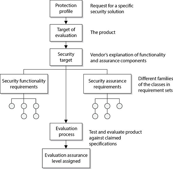
• Protection profile (PP) Description of a needed security solution.
• Target of evaluation (TOE) Product proposed to provide a needed security solution.
• Security target Vendor’s written explanation of the security functionality and assurance mechanisms that meet the needed security solution—in other words, “This is what our product does and how it does it.”
• Security functional requirements Individual security functions that must be provided by a product.
• Security assurance requirements Measures taken during development and evaluation of the product to assure compliance with the claimed security functionality.
• Packages—EALs Functional and assurance requirements are bundled into packages for reuse. This component describes what must be met to achieve specific EAL ratings.
ISO/IEC 15408 is the international standard that is used as the basis for the evaluation of security properties of products under the CC framework. It actually has three main parts:
• ISO/IEC 15408-1 Introduction and general model
• ISO/IEC 15408-2 Security functional components
• ISO/IEC 15408-3 Security assurance components
ISO/IEC 15408-1 lays out the general concepts and principles of the CC evaluation model. This part defines terms, establishes the core concept of the TOE, describes the evaluation context, and identifies the necessary audience. It provides the key concepts for PP, security requirements, and guidelines for the security target.
ISO/IEC 15408-2 defines the security functional requirements that will be assessed during the evaluation. It contains a catalog of predefined security functional components that maps to most security needs. These requirements are organized in a hierarchical structure of classes, families, and components. It also provides guidance on the specification of customized security requirements if no predefined security functional component exists.
ISO/IEC 15408-3 defines the assurance requirements, which are also organized in a hierarchy of classes, families, and components. This part outlines the evaluation assurance levels, which is a scale for measuring assurance of TOEs, and it provides the criteria for evaluation of protection profiles and security targets.
So product vendors follow these standards when building products that they will put through the CC evaluation process, and the product evaluators follow these standards when carrying out the evaluation processes.