
CHAPTER 4
Communication and Network Security
This chapter presents the following:
• OSI and TCP/IP models
• Protocol types and security issues
• LAN, WAN, MAN, intranet, and extranet technologies
• Transmission media
• Wireless technologies
• Network components and services
• Communications security management
• Remote access technologies
• Threats and attacks
• Software-defined networks
• Content distribution networks
• Multilayer protocols
• Convergent network technologies
The Internet… it’s a series of tubes.
—Ted Stevens
Telecommunications and networking use various mechanisms, devices, software, and protocols that are interrelated and integrated. Networking is one of the more complex topics in the computer field, mainly because so many technologies are involved. Our current technologies are constantly evolving, and every month there seems to be new “emerging” ones that we have to learn, understand, implement, and secure. A network administrator must know how to configure networking software, protocols and services, and devices; deal with interoperability issues; install, configure, and interface with telecommunications software and devices; and troubleshoot effectively. A security professional must understand these issues and be able to analyze them a few levels deeper to recognize fully where vulnerabilities can arise within each of these components and then know what to do about them. This can be a challenging task. However, if you are knowledgeable, have a solid practical skill set, and are willing to continue to learn, you can have more career opportunities than you know what to do with.
In this chapter we will start with the basics of networking and telecommunications and build upon them and identify many of the security issues that are involved.
Principles of Network Architectures
A network architecture is just a model of a network. Like any model, it is not 100 percent representative of reality and uses abstractions to simplify some details so that we can focus on the others. By ignoring the little stuff (for now), we make it easier on ourselves to decide some of the more important stuff. For example, before we decide how many web servers we need and which operating systems and software we need to run on them, we should first identify the classes of servers and where we would put them. We might have a set of externally accessible servers for our web presence, but we may also need some servers that are for internal use only by all employees, and yet another set that is only for web developers. Where do we put each set and how might we need different controls for them? Maybe we need a demilitarized zone (DMZ), an internal sharing cluster, and a development virtual local area network (VLAN), each with specific sets of controls meant to mitigate their differing risk profiles. A network architecture allows us to answer these high-level questions before we start configuring any boxes.
Now, once we go through all the trouble of coming up with an architecture that works, we shouldn’t have to reinvent the wheel. Network architectures also serve as templates for future systems. What’s more, they can be codified and shared among similar organizations to reduce work and ensure we all follow best practices. Even if a lot of the details are different, a sound architecture can be reused time and again.
Many of these best practices relate to security. Since we intend our architectures to be reusable, it is imperative that we apply secure design principles when we implement them. In the sections that follow, we will discuss a (wide) variety of networking concepts and technologies that you will need in order to implement secure design principles in network architectures. Periodically, we circle back and discuss some of these important secure design principles. It is important to note that there is no one-size-fits-all solution in this effort, so you will have to be selective about which of these principles you apply in any specific situation. Still, as a CISSP, you are expected to be conversant with all of them.
Open Systems Interconnection Reference Model
ISO is a worldwide federation that works to provide international standards. In the early 1980s, ISO worked to develop a protocol set that would be used by all vendors throughout the world to allow the interconnection of network devices. This movement was fueled with the hopes of ensuring that all vendor products and technologies could communicate and interact across international and technical boundaries. The actual protocol set did not catch on as a standard, but the model of this protocol set, the Open Systems Interconnection (OSI) reference model, was adopted and is used as an abstract framework to which most operating systems and protocols adhere.
Many people think that the OSI reference model arrived at the beginning of the computing age as we know it and helped shape and provide direction for many, if not all, networking technologies. However, this is not true. In fact, it was introduced in 1984, at which time the basics of the Internet had already been developed and implemented, and the basic Internet protocols had been in use for many years. The Transmission Control Protocol/Internet Protocol (TCP/IP) suite actually has its own model that is often used today when examining and understanding networking issues. Figure 4-1 shows the differences between the OSI and TCP/IP networking models. In this chapter, we will focus more on the OSI model.

Figure 4-1 The OSI and TCP/IP networking models

NOTE The host-to-host layer is sometimes called the transport layer in the TCP/IP model. The application layer in the TCP/IP architecture model is equivalent to a combination of the application, presentation, and session layers in the OSI model.
Protocol
A network protocol is a standard set of rules that determines how systems will communicate across networks. Two different systems that use the same protocol can communicate and understand each other despite their differences, similar to how two people can communicate and understand each other by using the same language.
The OSI reference model, as described by ISO Standard 7498-1, provides important guidelines used by vendors, engineers, developers, and others. The model segments the networking tasks, protocols, and services into different layers. Each layer has its own responsibilities regarding how two computers communicate over a network. Each layer has certain functionalities, and the services and protocols that work within that layer fulfill them.
The OSI model’s goal is to help others develop products that will work within an open network architecture. An open network architecture is one that no vendor owns, that is not proprietary, and that can easily integrate various technologies and vendor implementations of those technologies. Vendors have used the OSI model as a jumping-off point for developing their own networking frameworks. These vendors use the OSI model as a blueprint and develop their own protocols and services to produce functionality that is different from, or overlaps, that of other vendors. However, because these vendors use the OSI model as their starting place, integration of other vendor products is an easier task, and the interoperability issues are less burdensome than if the vendors had developed their own networking framework from scratch.
Although computers communicate in a physical sense (electronic signals are passed from one computer over a wire to the other computer), they also communicate through logical channels. Each protocol at a specific OSI layer on one computer communicates with a corresponding protocol operating at the same OSI layer on another computer. This happens through encapsulation.
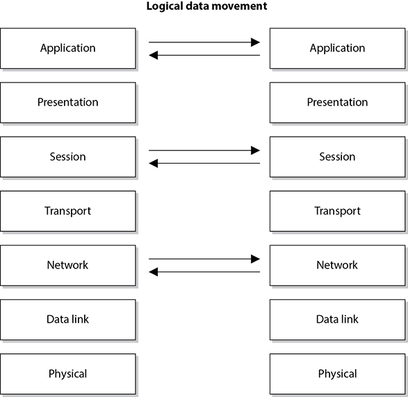
Here’s how encapsulation works: A message is constructed within a program on one computer and is then passed down through the network protocol’s stack. A protocol at each layer adds its own information to the message; thus, the message grows in size as it goes down the protocol stack. The message is then sent to the destination computer, and the encapsulation is reversed by taking the packet apart through the same steps used by the source computer that encapsulated it. At the data link layer, only the information pertaining to the data link layer is extracted, and the message is sent up to the next layer. Then at the network layer, only the network layer data is stripped and processed, and the packet is again passed up to the next layer, and so on. This is how computers communicate logically. The information stripped off at the destination computer informs it how to interpret and process the packet properly. Data encapsulation is shown in Figure 4-2.

Figure 4-2 Each OSI layer protocol adds its own information to the data packet.
A protocol at each layer has specific responsibilities and control functions it performs, as well as data format syntaxes it expects. Each layer has a special interface (connection point) that allows it to interact with three other layers: (1) communications from the interface of the layer above it, (2) communications to the interface of the layer below it, and (3) communications with the same layer in the interface of the target packet address. The control functions, added by the protocols at each layer, are in the form of headers and trailers of the packet.
The benefit of modularizing these layers, and the functionality within each layer, is that various technologies, protocols, and services can interact with each other and provide the proper interfaces to enable communications. This means a computer can use an application protocol developed by Novell, a transport protocol developed by Apple, and a data link protocol developed by IBM to construct and send a message over a network. The protocols, technologies, and computers that operate within the OSI model are considered open systems. Open systems are capable of communicating with other open systems because they implement international standard protocols and interfaces. The specification for each layer’s interface is very structured, while the actual code that makes up the internal part of the software layer is not defined. This makes it easy for vendors to write plug-ins in a modularized manner. Systems are able to integrate the plug-ins into the network stack seamlessly, gaining the vendor-specific extensions and functions.
Understanding the functionalities that take place at each OSI layer and the corresponding protocols that work at those layers helps you understand the overall communication process between computers. Once you understand this process, a more detailed look at each protocol will show you the full range of options each protocol provides and the security weaknesses embedded into each of those options.
Application Layer
The application layer, layer 7, works closest to the user and provides file transmissions, message exchanges, terminal sessions, and much more. This layer does not include the actual applications, but rather the protocols that support the applications. When an application needs to send data over the network, it passes instructions and the data to the protocols that support it at the application layer. This layer processes and properly formats the data and passes it down to the next layer within the OSI model. This happens until the data the application layer constructed contains the essential information from each layer necessary to transmit the data over the network. The data is then put on the network cable and transmitted until it arrives at the destination computer.
As an analogy, let’s say that you write a letter that you would like to send to your congressman. Your job is to write the letter, your clerk’s job is to figure out how to get it to him, and the congressman’s job is to read your letter and respond to it. You (the application) create the content (message) and hand it to your assistant (application layer protocol). Your assistant puts the content into an envelope, writes the congressman’s address on the envelope (inserts headers and trailers), and puts it into the mailbox (passes it on to the next protocol in the network stack). When your assistant checks the mailbox a week later, there is a letter from the congressman (the remote application) addressed to you. Your assistant opens the envelope (strips off headers and trailers) and gives you the message (passes the message up to the application).
Some examples of the protocols working at this layer are the Simple Mail Transfer Protocol (SMTP), Hypertext Transfer Protocol (HTTP), Domain Name System (DNS), Internet Relay Chat (IRC) protocol, and the Line Printer Daemon (LDP) protocol. Figure 4-3 shows how applications communicate with the underlying protocols through application programming interfaces (APIs). If a user makes a request to send an e-mail message through her e-mail client Outlook, the e-mail client sends this information to SMTP. SMTP adds its information to the user’s message and passes it down to the presentation layer.

Figure 4-3 Applications send requests to an API, which is the interface to the supporting protocol.
Presentation Layer
The presentation layer, layer 6, receives information from the application layer protocol and puts it in a format that any process operating at the same layer on a destination computer following the OSI model can understand. This layer provides a common means of representing data in a structure that can be properly processed by the end system. This means that when a user creates a Word document and sends it out to several people, it does not matter whether the receiving computers have different word processing programs; each of these computers will be able to receive this file and understand and present it to its user as a document. It is the data representation processing that is done at the presentation layer that enables this to take place. For example, when a Windows 8 computer receives a file from another computer system, information within the file’s header indicates what type of file it is. The Windows 8 operating system has a list of file types it understands and a table describing what program should be used to open and manipulate each of these file types. For example, the sender could create a Portable Document Format (PDF) file in Word 2010, while the receiver uses a Linux system. The receiver can open this file because the presentation layer on the sender’s system encoded the file and added a descriptive header in accordance with the Multipurpose Internet Mail Extensions (MIME) standards, and the receiver’s computer interprets the header’s MIME type (Content-Type: application/pdf), decodes the file, and knows to open it with its PDF viewer application.
The presentation layer is not concerned with the meaning of data, but with the syntax and format of that data. It works as a translator, translating the format an application is using to a standard format used for passing messages over a network. If a user uses a Corel application to save a graphic, for example, the graphic could be a Tagged Image File Format (TIFF), Graphic Interchange Format (GIF), or Joint Photographic Experts Group (JPEG) format. The presentation layer adds information to tell the destination computer the file type and how to process and present it. This way, if the user sends this graphic to another user who does not have the Corel application, the user’s operating system can still present the graphic because it has been saved into a standard format. Figure 4-4 illustrates the conversion of a file into different standard file types.
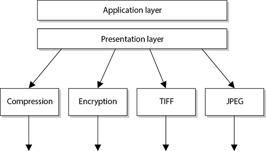
Figure 4-4 The presentation layer receives data from the application layer and puts it into a standard format.
This layer also handles data compression and encryption issues. If a program requests a certain file to be compressed and encrypted before being transferred over the network, the presentation layer provides the necessary information for the destination computer. It provides information on how the file was encrypted and/or compressed so that the receiving system knows what software and processes are necessary to decrypt and decompress the file. Let’s say Sara compresses a file using WinZip and sends it to you. When your system receives this file, it looks at data within the header (Content-Type: application/zip) and knows what application can decompress the file. If your system has WinZip installed, then the file can be decompressed and presented to you in its original form. If your system does not have an application that understands the compression/decompression instructions, the file will be presented to you with an unassociated icon.
Session Layer
When two applications need to communicate or transfer data between themselves, a connection may need to be set up between them. The session layer, layer 5, is responsible for establishing a connection between the two applications, maintaining it during the transfer of data, and controlling the release of this connection. A good analogy for the functionality within this layer is a telephone conversation. When Kandy wants to call a friend, she uses the telephone. The telephone network circuitry and protocols set up the connection over the telephone lines and maintain that communication path, and when Kandy hangs up, they release all the resources they were using to keep that connection open.
Similar to how telephone circuitry works, the session layer works in three phases: connection establishment, data transfer, and connection release. It provides session restart and recovery if necessary and provides the overall maintenance of the session. When the conversation is over, this path is broken down and all parameters are set back to their original settings. This process is known as dialog management. Figure 4-5 depicts the three phases of a session. Some protocols that work at this layer are the Password Authentication Protocol (PAP), Point-to-Point Tunneling Protocol (PPTP), Network Basic Input Output System (NetBIOS), and Remote Procedure Call (RPC).
The session layer protocol can enable communication between two applications to happen in three different modes:
• Simplex Communication takes place in one direction, though in practice this is very seldom the case.
• Half-duplex Communication takes place in both directions, but only one application can send information at a time.
• Full-duplex Communication takes place in both directions, and both applications can send information at the same time.
Many people have a hard time understanding the difference between what takes place at the session layer versus the transport layer because their definitions sound similar. Session layer protocols control application-to-application communication, whereas the transport layer protocols handle computer-to-computer communication. For example, if you are using a product that is working in a client/server model, in reality you have a small piece of the product on your computer (client portion) and the larger piece of the software product is running on a different computer (server portion). The communication between these two pieces of the same software product needs to be controlled, which is why session layer protocols even exist. Session layer protocols take on the functionality of middleware, which allows software on two different computers to communicate.
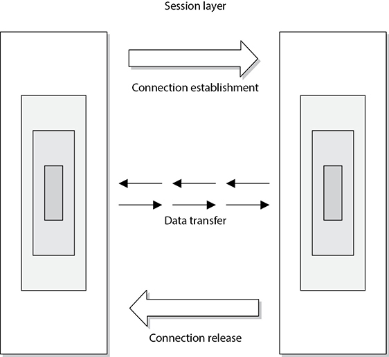
Figure 4-5 The session layer sets up the connection, maintains it, and tears it down once communication is completed.
Session layer protocols provide interprocess communication channels, which allow a piece of software on one system to call upon a piece of software on another system without the programmer having to know the specifics of the software on the receiving system. The programmer of a piece of software can write a function call that calls upon a subroutine. The subroutine could be local to the system or be on a remote system. If the subroutine is on a remote system, the request is carried over a session layer protocol. The result that the remote system provides is then returned to the requesting system over the same session layer protocol. This is how RPC works. A piece of software can execute components that reside on another system. This is the core of distributed computing.

CAUTION One security issue common to RPC (and similar interprocess communication software) is the lack of authentication or the use of weak authentication. Secure RPC (SRPC) can be implemented, which requires authentication to take place before two computers located in different locations can communicate with each other. Authentication can take place using shared secrets, public keys, or Kerberos tickets. Session layer protocols need to provide secure authentication capabilities.
Session layer protocols are the least used protocols in a network environment; thus, many of them should be disabled on systems to decrease the chance of them getting exploited. RPC, NetBIOS, and similar distributed computing calls usually only need to take place within a network; thus, firewalls should be configured so this type of traffic is not allowed into or out of a network. Firewall filtering rules should be in place to stop this type of unnecessary and dangerous traffic.
Transport Layer
When two computers are going to communicate through a connection-oriented protocol, they will first agree on how much information each computer will send at a time, how to verify the integrity of the data once received, and how to determine whether a packet was lost along the way. The two computers agree on these parameters through a handshaking process at the transport layer, layer 4. The agreement on these issues before transferring data helps provide more reliable data transfer, error detection, correction, recovery, and flow control, and it optimizes the network services needed to perform these tasks. The transport layer provides end-to-end data transport services and establishes the logical connection between two communicating computers.
NOTE Connection-oriented protocols, such as Transmission Control Protocol (TCP), provide reliable data transmission when compared to connectionless protocols, such as User Datagram Protocol (UDP). This distinction is covered in more detail in the “TCP/IP Model” section, later in the chapter.
The functionality of the session and transport layers is similar insofar as they both set up some type of session or virtual connection for communication to take place. The difference is that protocols that work at the session layer set up connections between applications, whereas protocols that work at the transport layer set up connections between computer systems. For example, we can have three different applications on computer A communicating with three applications on computer B. The session layer protocols keep track of these different sessions. You can think of the transport layer protocol as the bus. It does not know or care what applications are communicating with each other. It just provides the mechanism to get the data from one system to another.
The transport layer receives data from many different applications and assembles the data into a stream to be properly transmitted over the network. The main protocols that work at this layer are TCP and UDP. Information is passed down from different entities at higher layers to the transport layer, which must assemble the information into a stream, as shown in Figure 4-6. The stream is made up of the various data segments passed to it. Just like a bus can carry a variety of people, the transport layer protocol can carry a variety of application data types.

TIP Different references can place specific protocols at different layers. For example, many references place the Transport Layer Security (TLS) protocol in the session layer, while other references place it in the transport layer. It is not that one is right or wrong. The OSI model tries to draw boxes around reality, but some protocols straddle the different layers.
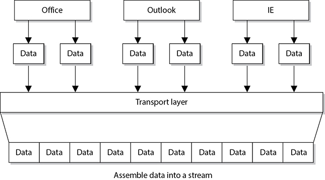
Figure 4-6 TCP formats data from applications into a stream to be prepared for transmission.
Network Layer
The main responsibilities of the network layer, layer 3, are to insert information into the packet’s header so it can be properly addressed and routed, and then to actually route the packets to their proper destination. In a network, many routes can lead to one destination. The protocols at the network layer must determine the best path for the packet to take. Routing protocols build and maintain their routing tables. These tables are maps of the network, and when a packet must be sent from computer A to computer M, the protocols check the routing table, add the necessary information to the packet’s header, and send it on its way.
The protocols that work at this layer do not ensure the delivery of the packets. They depend on the protocols at the transport layer to catch any problems and resend packets if necessary. The Internet Protocol (IP) is a common protocol working at the network layer, although other routing and routed protocols work there as well. Some of the other protocols are the Internet Control Message Protocol (ICMP), Routing Information Protocol (RIP), Open Shortest Path First (OSPF), Border Gateway Protocol (BGP), and Internet Group Management Protocol (IGMP). Figure 4-7 shows that a packet can take many routes and that the network layer enters routing information into the header to help the packet arrive at its destination.
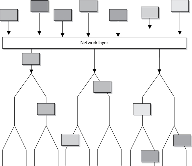
Figure 4-7 The network layer determines the most efficient path for each packet to take.
Data Link Layer
As we continue down the protocol stack, we are getting closer to the actual transmission channel (i.e., network wire) over which all the data will travel. The outer format of the data packet changes slightly at each layer, and it comes to a point where it needs to be translated into the LAN or wide area network (WAN) technology binary format for proper line transmission. This happens at the data link layer, layer 2.
LAN and WAN technologies can use different protocols, network interface cards (NICs), cables, and transmission methods. Each of these components has a different header data format structure, and they interpret electromagnetic signals in different ways. The data link layer is where the network stack knows in what format the data frame must be in order to transmit it properly over Token Ring, Ethernet, ATM, or Fiber Distributed Data Interface (FDDI) networks. If the network is an Ethernet network, for example, all the computers will expect packet headers to be a certain length, the flags to be positioned in certain field locations within the header, and the trailer information to be in a certain place with specific fields. Compared to Ethernet, Token Ring network technology has different frame header lengths, flag values, and header formats.
The data link layer is divided into two functional sublayers: the Logical Link Control (LLC) and the Media Access Control (MAC). The LLC, which was originally defined in the IEEE 802.2 specification for Ethernet networks and is now also the ISO/IEC 8802-2 standard, communicates with the protocol immediately above it, the network layer. The MAC will have the appropriately loaded protocols to interface with the protocol requirements of the physical layer.
As data is passed down the network stack, it has to go from the network layer to the data link layer. The protocol at the network layer does not know if the underlying network is Ethernet, Token Ring, or ATM—it does not need to have this type of insight. The protocol at the network layer just adds its header and trailer information to the packet and passes it on to the next layer, which is the LLC sublayer. The LLC sublayer takes care of flow control and error checking. Data coming from the network layer passes down through the LLC sublayer and goes to the MAC. The technology at the MAC sublayer knows if the network is Ethernet, Token Ring, or ATM, so it knows how to put the last header and trailer on the packet before it “hits the wire” for transmission.
The IEEE MAC specification for Ethernet is 802.3, Token Ring is 802.5, wireless LAN is 802.11, and so on. So when you see a reference to an IEEE standard, such as 802.11, 802.16, or 802.3, it refers to the protocol working at the MAC sublayer of the data link layer of a protocol stack.
Some of the protocols that work at the data link layer are the Point-to-Point Protocol (PPP), ATM, Layer 2 Tunneling Protocol (L2TP), FDDI, Ethernet, and Token Ring. Figure 4-8 shows the two sublayers that make up the data link layer.
Each network technology (Ethernet, ATM, FDDI, and so on) defines the compatible physical transmission type (coaxial, twisted pair, fiber, wireless) that is required to enable network communication. Each network technology also has defined electronic signaling and encoding patterns. For example, if the MAC sublayer received a bit with the value of 1 that needed to be transmitted over an Ethernet network, the MAC sublayer technology would tell the physical layer to create a +0.5-volt electric signal. In the “language of Ethernet” this means that 0.5 volts is the encoding value for a bit with the value of 1. If the next bit the MAC sublayer receives is 0, the MAC layer would tell the physical layer to transmit 0 volts. The different network types will have different encoding schemes. So a bit value of 1 in an ATM network might actually be encoded to the voltage value of 0.85. It is just a sophisticated Morse code system. The receiving end will know when it receives a voltage value of 0.85 that a bit with the value of 1 has been transmitted.

Figure 4-8 The data link layer is made up of two sublayers.
Network cards bridge the data link and physical layers. Data is passed down through the first six layers and reaches the network card driver at the data link layer. Depending on the network technology being used (Ethernet, Token Ring, FDDI, and so on), the network card driver encodes the bits at the data link layer, which are then turned into electricity states at the physical layer and placed onto the wire for transmission.

EXAM TIP When the data link layer applies the last header and trailer to the data message, this is referred to as framing. The unit of data is now called a frame.
Physical Layer
The physical layer, layer 1, converts bits into voltage for transmission. Signals and voltage schemes have different meanings for different LAN and WAN technologies, as covered earlier. If a user sends data through his dial-up software and out his modem onto a telephone line, the data format, electrical signals, and control functionality are much different than if that user sends data through the NIC and onto a unshielded twisted pair (UTP) wire for LAN communication. The mechanisms that control this data going onto the telephone line, or the UTP wire, work at the physical layer. This layer controls synchronization, data rates, line noise, and transmission techniques. Specifications for the physical layer include the timing of voltage changes, voltage levels, and the physical connectors for electrical, optical, and mechanical transmission.
EXAM TIP To remember all the layers within the OSI model in the correct order, memorize “All People Seem To Need Data Processing.” Remember that you are starting at layer 7, the application layer, at the top.
Functions and Protocols in the OSI Model
For the CISSP exam, you will need to know the functionality that takes place at the different layers of the OSI model, along with specific protocols that work at each layer. The following is a quick overview of each layer and its components.
Application
The protocols at the application layer handle file transfer, virtual terminals, network management, and fulfilling networking requests of applications. A few of the protocols that work at this layer include
• File Transfer Protocol (FTP)
• Trivial File Transfer Protocol (TFTP)
• Simple Network Management Protocol (SNMP)
• Simple Mail Transfer Protocol (SMTP)
• Telnet
• Hypertext Transfer Protocol (HTTP)
Presentation
The services of the presentation layer handle translation into standard formats, data compression and decompression, and data encryption and decryption. No protocols work at this layer, just services. The following lists some of the presentation layer standards:
• American Standard Code for Information Interchange (ASCII)
• Extended Binary-Coded Decimal Interchange Mode (EBCDIC)
• Tagged Image File Format (TIFF)
• Joint Photographic Experts Group (JPEG)
• Motion Picture Experts Group (MPEG)
• Musical Instrument Digital Interface (MIDI)
Session
The session layer protocols set up connections between applications; maintain dialog control; and negotiate, establish, maintain, and tear down the communication channel. Some of the protocols that work at this layer include
• Network Basic Input Output System (NetBIOS)
• Password Authentication Protocol (PAP)
• Point-to-Point Tunneling Protocol (PPTP)
• Remote Procedure Call (RPC)
Transport
The protocols at the transport layer handle end-to-end transmission and segmentation of a data stream. The following protocols work at this layer:
• Transmission Control Protocol (TCP)
• User Datagram Protocol (UDP)
• Sequenced Packet Exchange (SPX)
Network
The responsibilities of the network layer protocols include internetworking service, addressing, and routing. The following lists some of the protocols that work at this layer:
• Internet Protocol (IP)
• Internet Control Message Protocol (ICMP)
• Internet Group Management Protocol (IGMP)
• Routing Information Protocol (RIP)
• Open Shortest Path First (OSPF)
• Internetwork Packet Exchange (IPX)
Data Link
The protocols at the data link layer convert data into LAN or WAN frames for transmission and define how a computer accesses a network. This layer is divided into the Logical Link Control (LLC) and the Media Access Control (MAC) sublayers. Some protocols that work at this layer include the following:
• Address Resolution Protocol (ARP)
• Reverse Address Resolution Protocol (RARP)
• Point-to-Point Protocol (PPP)
• Serial Line Internet Protocol (SLIP)
• Ethernet (IEEE 802.3)
• Token Ring (IEEE 802.5)
• Wireless Ethernet (IEEE 802.11)
Physical
Network interface cards and drivers convert bits into electrical signals and control the physical aspects of data transmission, including optical, electrical, and mechanical requirements. The following are some of the standard interfaces at this layer:
• RS/EIA/TIA-422, RS/EIA/TIA-423, RS/EIA/TIA-449, RS/EIA/TIA-485
• 10Base-T, 10Base2, 10Base5, 100Base-TX, 100Base-FX, 100Base-T, 1000Base-T, 1000Base-SX
• Integrated Services Digital Network (ISDN)
• Digital subscriber line (DSL)
• Synchronous Optical Networking (SONET)
Tying the Layers Together
The OSI model is used as a framework for many network-based products and is used by many types of vendors. Various types of devices and protocols work at different parts of this seven-layer model. The main reason that a Cisco switch, Microsoft web server, a Barracuda firewall, and a Belkin wireless access point can all communicate properly on one network is because they all work within the OSI model. They do not have their own individual ways of sending data; they follow a standardized manner of communication, which allows for interoperability and allows a network to be a network. If a product does not follow the OSI model, it will not be able to communicate with other devices on the network because the other devices will not understand its proprietary way of communicating.
The different device types work at specific OSI layers. For example, computers can interpret and process data at each of the seven layers, but routers can understand information only up to the network layer because a router’s main function is to route packets, which does not require knowledge about any further information within the packet. A router peels back the header information until it reaches the network layer data, where the routing and IP address information is located. The router looks at this information to make its decisions on where the packet should be routed. Bridges and switches understand only up to the data link layer, and repeaters understand traffic only at the physical layer. So if you hear someone mention a “layer 3 device,” the person is referring to a device that works at the network layer. A “layer 2 device” works at the data link layer. Figure 4-9 shows what layer of the OSI model each type of device works within.
NOTE Some techies like to joke that all computer problems reside at layer 8. The OSI model does not have an eighth layer, and what these people are referring to is the user of a computer. So if someone states that there is a problem at layer 8, this is code for “the user is the problem.”
Let’s walk through an example. You open an FTP client on your computer and connect to an FTP server on your network. In your FTP client you choose to download a photo from a server. The FTP server now has to move this file over the network to your computer. The server sends this document to the FTP application protocol on its network stack. This FTP protocol puts headers and trailers on the document and passes it down to the presentation layer. A service at the presentation layer adds a header that indicates this document is in JPEG format so that your system knows how to open the file when it is received.
This bundle is then handed to the transport layer TCP, which also adds a header and trailer, which include source and destination port values. The bundle continues down the network stack to the IP protocol, which provides a source IP address (FTP server) and a destination IP address (your system). The bundle goes to the data link layer, and the server’s NIC driver encodes the bundle to be able to be transmitted over the Ethernet connection between the server and your system.
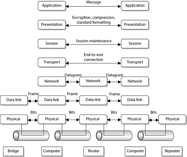
Figure 4-9 Each device works at a particular layer within the OSI model.
Multilayer Protocols
Not all protocols fit neatly within the layers of the OSI model. This is particularly evident among devices and networks that were never intended to interoperate with the Internet. For this same reason, they tend to lack robust security features aimed at protecting the availability, integrity, and confidentiality of the data they communicate. The problem is that as the Internet of old becomes the Internet of Things (IoT), these previously isolated devices and networks find themselves increasingly connected to a host of threats they were never meant to face.
As security professionals, we need to be aware of these nontraditional protocols and their implications for the security of the networks to which they are connected. In particular, we should be vigilant when it comes to identifying nonobvious cyber-physical systems. In December 2015, attackers were able to cut power to over 80,000 homes in Ukraine apparently by compromising the utilities’ supervisory control and data acquisition (SCADA) systems in what is considered the first known blackout caused by a cyberattack. At the heart of most SCADA systems used by power and water utilities is a multilayer protocol known as DNP3.
Distributed Network Protocol 3
The Distributed Network Protocol 3 (DNP3) is a communications protocol designed for use in SCADA systems, particularly those within the power sector. It is not a general-purpose protocol like IP, nor does it incorporate routing functionality. SCADA systems typically have a very flat hierarchical architecture in which sensors and actuators are connected to remote terminal units (RTUs). The RTUs aggregate data from one or more of these devices and relay it to the SCADA master, which includes a human-machine interface (HMI) component. Control instructions and configuration changes are sent from the SCADA master to the RTUs and then on to the sensors and actuators.
At the time DNP3 was designed, there wasn’t a need to route traffic among the components (most of which were connected with point-to-point circuits), so networking was not needed or supported in DNP3. Instead of using the OSI seven-layer model, its developers opted for a simpler three-layer model called the Enhanced Performance Architecture (EPA) that roughly corresponds to layers 2, 4, and 7 of the OSI model. There was no encryption or authentication, since the developers did not think network attacks were feasible on a system consisting of devices connected to each other and to nothing else.
Over time, SCADA systems were connected to other networks and then to the Internet for a variety of very valid business reasons. Unfortunately, security wasn’t considered until much later. Encryption and authentication features were added as an afterthought, though not all implementations have been thus updated. Network segmentation is not always present either, even in some critical installations. Perhaps most concerning is the shortage of effective intrusion prevention systems (IPSs) and intrusion detection systems (IDSs) that understand the interconnections between DNP3 and IP networks and can identify DNP3-based attacks.
Controller Area Network Bus
Another multilayer protocol that had almost no security features until very recently is the one that runs most automobiles worldwide. The Controller Area Network bus (CAN bus) is a protocol designed to allow microcontrollers and other embedded devices to communicate with each other on a shared bus. Over time, these devices have diversified so that today they can control almost every aspect of a vehicle’s functions, including steering, braking, and throttling. CAN bus was never meant to communicate with anything outside the vehicle except for a mechanic’s maintenance computer, so there never appeared to be a need for security features.
As cars started getting connected via Wi-Fi and cellular data networks, their designers didn’t fully consider the new attack vectors this would introduce to an otherwise undefended system. That is, until Charlie Miller and Chris Valasek famously hacked a Jeep in 2015 by connecting to it over a cellular data network and bridging the head unit (which controls the sound system and GPS) to the CAN bus (which controls all the vehicle sensors and actuators) and causing it to run off a road. As cars become more autonomous, security of the CAN bus will become increasingly important.
TCP/IP Model
The Transmission Control Protocol/Internet Protocol (TCP/IP) is a suite of protocols that governs the way data travels from one device to another. Besides its eponymous two main protocols, TCP/IP includes other protocols as well, which we will cover in this chapter.
IP is a network layer protocol and provides datagram routing services. IP’s main task is to support internetwork addressing and packet routing. It is a connectionless protocol that envelops data passed to it from the transport layer. The IP protocol addresses the datagram with the source and destination IP addresses. The protocols within the TCP/IP suite work together to break down the data passed from the application layer into pieces that can be moved along a network. They work with other protocols to transmit the data to the destination computer and then reassemble the data back into a form that the application layer can understand and process.
Two main protocols work at the transport layer: TCP and UDP. TCP is a reliable and connection-oriented protocol, which means it ensures packets are delivered to the destination computer. If a packet is lost during transmission, TCP has the ability to identify this issue and resend the lost or corrupted packet. TCP also supports packet sequencing (to ensure each and every packet was received), flow and congestion control, and error detection and correction. UDP, on the other hand, is a best-effort and connectionless protocol. It has neither packet sequencing nor flow and congestion control, and the destination does not acknowledge every packet it receives.
TCP
TCP is referred to as a connection-oriented protocol because before any user data is actually sent, handshaking takes place between the two systems that want to communicate. Once the handshaking completes successfully, a virtual connection is set up between the two systems. UDP is considered a connectionless protocol because it does not go through these steps. Instead, UDP sends out messages without first contacting the destination computer and does not know if the packets were received properly or dropped. Figure 4-10 shows the difference between a connection-oriented protocol and a connectionless protocol.
UDP and TCP sit together on the transport layer, and developers can choose which to use when developing applications. Many times, TCP is the transport protocol of choice because it provides reliability and ensures the packets are delivered. For example, SMTP is used to transmit e-mail messages and uses TCP because it must make sure the data is delivered. TCP provides a full-duplex, reliable communication mechanism, and if any packets are lost or damaged, they are re-sent; however, TCP requires a lot of system overhead compared to UDP.
If a programmer knows that data being dropped during transmission is not detrimental to the application, he may choose to use UDP because it is faster and requires fewer resources. For example, UDP is a better choice than TCP when a server sends status information to all listening nodes on the network. A node will not be negatively affected if, by some chance, it did not receive this status information, because the information will be re-sent every 60 seconds.
UDP and TCP are transport protocols that applications use to get their data across a network. They both use ports to communicate with upper OSI layers and to keep track of various conversations that take place simultaneously. The ports are also the mechanism used to identify how other computers access services. When a TCP or UDP message is formed, source and destination ports are contained within the header information along with the source and destination IP addresses. The combination of protocol (TCP or UDP), port, and IP address makes up a socket, and is how packets know where to go (by the address) and how to communicate with the right service or protocol on the other computer (by the port number). The IP address acts as the doorway to a computer, and the port acts as the doorway to the actual protocol or service. To communicate properly, the packet needs to know these doors. Figure 4-11 shows how packets communicate with applications and services through ports.
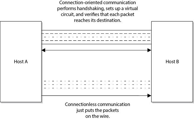
Figure 4-10 Connection-oriented protocol vs. connectionless protocol functionality
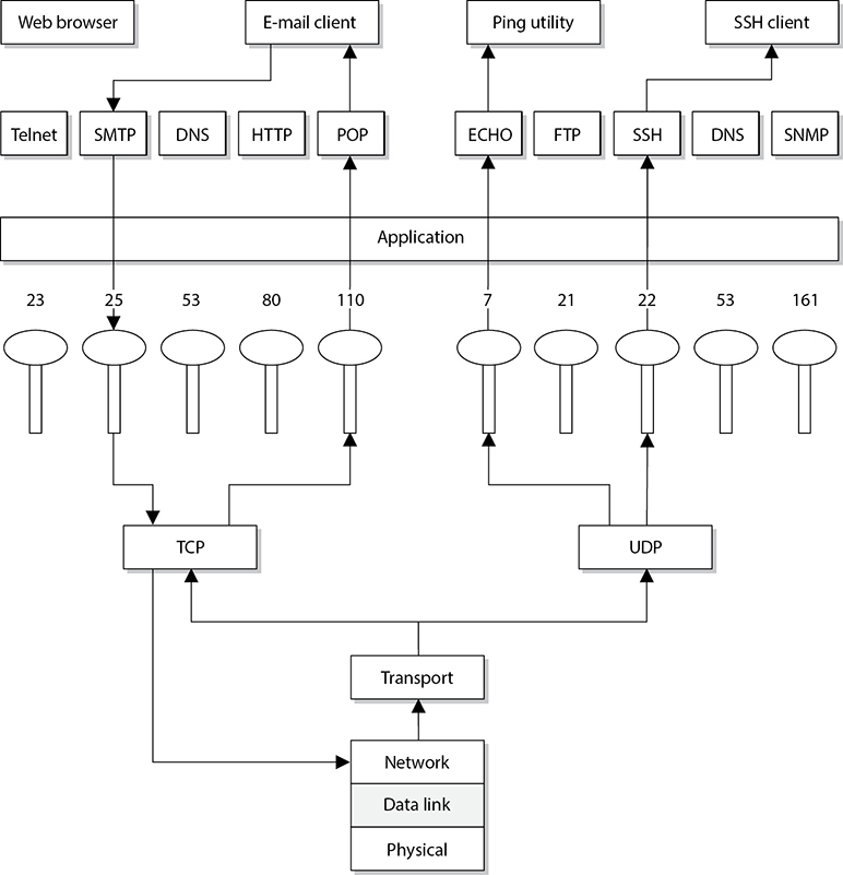
Figure 4-11 The packet can communicate with upper-layer protocols and services through a port.
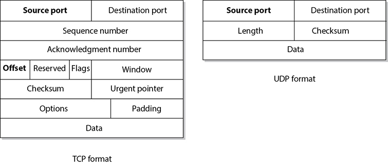
Figure 4-12 TCP carries a lot more information within its segment because it offers more services than UDP.
The difference between TCP and UDP can also be seen in the message formats. Because TCP offers more services than UDP, it must contain much more information within its packet header format, as shown in Figure 4-12. Table 4-1 lists the major differences between TCP and UDP.

Table 4-1 Major Differences Between TCP and UDP
TCP Handshake
TCP must set up a virtual connection between two hosts before any data is sent. This means the two hosts must agree on certain parameters, data flow, windowing, error detection, and options. These issues are negotiated during the handshaking phase, as shown in Figure 4-13.
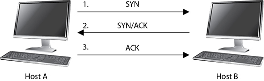
Figure 4-13 The TCP three-way handshake
The host that initiates communication sends a synchronization (SYN) packet to the receiver. The receiver acknowledges this request by sending a SYN/ACK packet. This packet translates into, “I have received your request and am ready to communicate with you.” The sending host acknowledges this with an acknowledgment (ACK) packet, which translates into, “I received your acknowledgment. Let’s start transmitting our data.” This completes the handshaking phase, after which a virtual connection is set up, and actual data can now be passed. The connection that has been set up at this point is considered full duplex, which means transmission in both directions is possible using the same transmission line.
If an attacker sends a target system SYN packets with a spoofed address, then the victim system replies to the spoofed address with SYN/ACK packets. Each time the victim system receives one of these SYN packets, it sets aside resources to manage the new connection. If the attacker floods the victim system with SYN packets, eventually the victim system allocates all of its available TCP connection resources and can no longer process new requests. This is a type of DoS that is referred to as a SYN flood. To thwart this type of attack you can use a number of mitigations, the most common of which are described in Internet Engineering Task Force’s (IETF) Request for Comments (RFC) 4987. One of the most effective techniques described in RFC 4987 is the use of SYN caches, which delays the allocation of a socket until the handshake is completed.
Another attack vector we need to understand is TCP sequence numbers. One of the values that is agreed upon during a TCP handshake between two systems is the sequence numbers that will be inserted into the packet headers. Once the sequence number is agreed upon, if a receiving system receives a packet from the sending system that does not have this predetermined value, it will disregard the packet. This means that an attacker cannot just spoof the address of a sending system to fool a receiving system; the attacker has to spoof the sender’s address and use the correct sequence number values. If an attacker can correctly predict the TCP sequence numbers that two systems will use, then she can create packets containing those numbers and fool the receiving system into thinking that the packets are coming from the authorized sending system. She can then take over the TCP connection between the two systems, which is referred to as TCP session hijacking.
Data Structures
As stated earlier, the message is formed and passed to the application layer from a program and sent down through the protocol stack. Each protocol at each layer adds its own information to the message and passes it down to the next layer. This activity is referred to as data encapsulation. As the message is passed down the stack, it goes through a sort of evolution, and each stage has a specific name that indicates what is taking place. When an application formats data to be transmitted over the network, the data is called a message or data. The message is sent to the transport layer, where TCP does its magic on it. The bundle of data is now a segment. The segment is sent to the network layer. The network layer adds routing and addressing, and now the bundle is called a packet. The network layer passes off the packet to the data link layer, which frames the packet with a header and a trailer, and now it is called a frame. Figure 4-14 illustrates these stages.
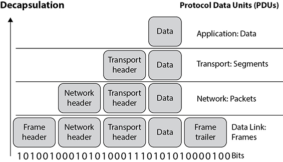
Figure 4-14 Data goes through its own evolutionary stages as it passes through the layers within the network stack.
EXAM TIP If the message is being transmitted over TCP, it is referred to as a “segment.” If it is being transmitted over UDP, it is referred to as a “datagram.”
Sometimes when an author refers to a segment, she is specifying the stage in which the data is located within the protocol stack. If the literature is describing routers, which work at the network layer, the author might use the word “packet” because the data at this layer has routing and addressing information attached. If an author is describing network traffic and flow control, she might use the word “frame” because all data actually ends up in the frame format before it is put on the network wire.
The important thing here is that you understand the various steps a data package goes through when it moves up and down the protocol stack.
IP Addressing
Each node on a network must have a unique IP address. Today, the most commonly used version of IP is IP version 4 (IPv4), but its addresses are in such high demand that their supply has started to run out. IP version 6 (IPv6) was created to address this shortage. (IPv6 also has many security features built into it that are not part of IPv4.) IPv6 is covered later in this chapter.
IPv4 uses 32 bits for its addresses, whereas IPv6 uses 128 bits; thus, IPv6 provides more possible addresses with which to work. Each address has a host portion and a network portion, and the addresses are grouped into classes and then into subnets. The subnet mask of the address differentiates the groups of addresses that define the subnets of a network. IPv4 address classes are listed in Table 4-2.
For any given IP network within an organization, all nodes connected to the network can have different host addresses but a common network address. The host address identifies every individual node, whereas the network address is the identity of the network all the nodes are connected to; therefore, it is the same for each one of them. Any traffic meant for nodes on this network will be sent to the prescribed network address.

Table 4-2 IPv4 Addressing
A subnet is created from the host portion of an IP address to designate a “sub” network. This allows us to further break the host portion of the address into two or more logical groupings, as shown in Figure 4-15. A network can be logically partitioned to reduce administration headaches, traffic performance, and potentially security. As an analogy, let’s say you work at Toddlers R Us and you are responsible for babysitting 100 toddlers. If you kept all 100 toddlers in one room, you would probably end up crazy. To better manage these kids, you could break them up into groups. The three-year-olds go in the yellow room, the four-year-olds go in the green room, and the five-year-olds go in the blue room. This is what a network administrator would do—break up and separate computer nodes to be able to better control them. Instead of putting them into physical rooms, the administrator puts them into logical rooms (subnets).
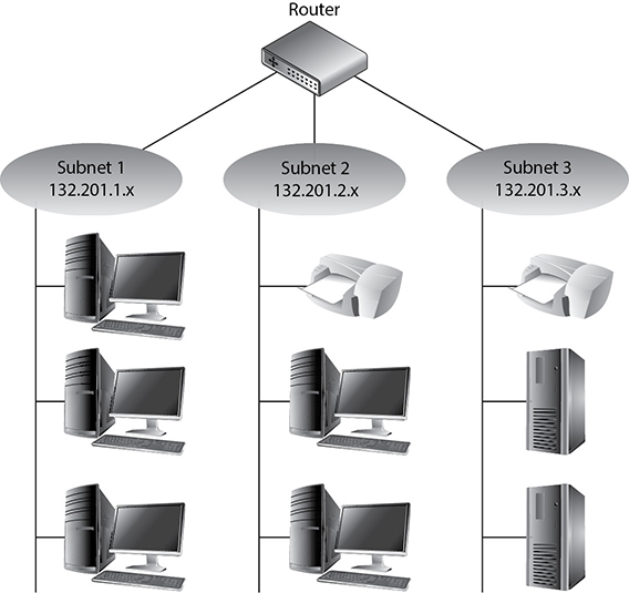
Figure 4-15 Subnets create logical partitions.
To continue with our analogy, when you put your toddlers in different rooms, you would have physical barriers that separate them—walls. Network subnetting is not physical; it is logical. This means you would not have physical walls separating your individual subnets, so how do you keep them separate? This is where subnet masks come into play. A subnet mask defines smaller networks inside a larger network, just like individual rooms are defined within a building.
Subnetting allows larger IP ranges to be divided into smaller, logical, and more tangible network segments. Consider an organization with several divisions, such as IT, Accounting, HR, and so on. Creating subnets for each division breaks the networks into logical partitions that route traffic directly to recipients without dispersing data all over the network. This drastically reduces the traffic load across the network, reducing the possibility of network congestion and excessive broadcast packets in the network. Implementing network security policies is also much more effective across logically categorized subnets with a demarcated perimeter, as compared to a large, cluttered, and complex network.
Subnetting is particularly beneficial in keeping down routing table sizes because external routers can directly send data to the actual network segment without having to worry about the internal architecture of that network and getting the data to individual hosts. This job can be handled by the internal routers, which can determine the individual hosts in a subnetted environment and save the external routers the hassle of analyzing all 32 bits of an IP address and just look at the “masked” bits.
TIP You should not have to calculate any subnets for the CISSP exam, but for a better understanding of how this stuff works under the hood, visit https://www.lifewire.com/internet-protocol-tutorial-subnets-818378. Keep in mind that URLs are subject to change from time to time.
If the traditional subnet masks are used, they are referred to as classful or classical IP addresses. If an organization needs to create subnets that do not follow these traditional sizes, then it would use classless IP addresses. This just means a different subnet mask would be used to define the network and host portions of the addresses. After it became clear that available IP addresses were running out as more individuals and corporations participated on the Internet, classless interdomain routing (CIDR) was created. A Class B address range is usually too large for most companies, and a Class C address range is too small, so CIDR provides the flexibility to increase or decrease the class sizes as necessary. CIDR is the method to specify more flexible IP address classes. CIDR is also referred to as supernetting.
NOTE To better understand CIDR, visit the following resource: www.tcpipguide.com/free/t_IPClasslessAddressingClasslessInterDomainRoutingCI.htm.
Although each node has an IP address, people usually refer to their hostname rather than their IP address. Hostnames, such as www.mheducation.com, are easier for humans to remember than IP addresses, such as 198.105.254.228. However, the use of these two nomenclatures requires mapping between the hostnames and IP addresses because the computer understands only the numbering scheme. This process is addressed in the “Domain Name Service” section later in this chapter.
NOTE IP provides addressing, packet fragmentation, and packet timeouts. To ensure that packets do not continually traverse a network forever, IP provides a Time to Live (TTL) value that is decremented every time the packet passes through a router. IP can also provide a Type of Service (ToS) capability, which means it can prioritize different packets for time-sensitive functions.
IPv6
IPv6, also called IP next generation (IPng), not only has a larger address space than IPv4 to support more IP addresses; it has some capabilities that IPv4 does not and it accomplishes some of the same tasks differently. All of the specifics of the new functions within IPv6 are beyond the scope of this book, but we will look at a few of them, because IPv6 is the way of the future. IPv6 allows for scoped addresses, which enables an administrator to restrict specific addresses for specific servers or file and print sharing, for example. IPv6 has Internet Protocol Security (IPSec) integrated into the protocol stack, which provides end-to-end secure transmission and authentication. IPv6 has more flexibility and routing capabilities and allows for Quality of Service (QoS) priority values to be assigned to time-sensitive transmissions. The protocol offers autoconfiguration, which makes administration much easier, and it does not require network address translation (NAT) to extend its address space.
NAT was developed because IPv4 addresses were running out. Although the NAT technology is extremely useful, it has caused a lot of overhead and transmission problems because it breaks the client/server model that many applications use today. One reason the industry did not jump on the IPv6 bandwagon when it came out years ago is that NAT was developed, which reduced the speed at which IP addresses were being depleted. Although the conversion rate from IPv4 to IPv6 is slow in some parts of the world and the implementation process is quite complicated, the industry is making the shift because of all the benefits that IPv6 brings to the table.
NOTE NAT is covered in the “Network Address Translation” section later in this chapter.
The IPv6 specification, as outlined in RFC 2460, lays out the differences and benefits of IPv6 over IPv4. A few of the differences are as follows:
• IPv6 increases the IP address size from 32 bits to 128 bits to support more levels of addressing hierarchy, a much greater number of addressable nodes, and simpler autoconfiguration of addresses.
• The scalability of multicast routing is improved by adding a “scope” field to multicast addresses. Also, a new type of address called an anycast address is defined, which is used to send a packet to any one of a group of nodes.
• Some IPv4 header fields have been dropped or made optional to reduce the common-case processing cost of packet handling and to limit the bandwidth cost of the IPv6 header. This is illustrated in Figure 4-16.
• Changes in the way IP header options are encoded allow for more efficient forwarding, less stringent limits on the length of options, and greater flexibility for introducing new options in the future.
• A new capability is added to enable the labeling of packets belonging to particular traffic “flows” for which the sender requests special handling, such as nondefault QoS or “real-time” service.
• Extensions to support authentication, data integrity, and (optional) data confidentiality are also specified for IPv6.
IPv4 limits packets to 65,535 bytes of payload, and IPv6 extends this size to 4,294,967,295 bytes. These larger packets are referred to as jumbograms and improve performance over high-maximum transmission unit (MTU) links. Currently most of the world still uses IPv4, but IPv6 is being deployed more rapidly. This means that there are “pockets” of networks using IPv4 and “pockets” of networks using IPv6 that still need to communicate. This communication takes place through different tunneling techniques, which either encapsulate IPv6 packets within IPv4 packets or carry out automated address translations. Automatic tunneling is a technique where the routing infrastructure automatically determines the tunnel endpoints so that protocol tunneling can take place without preconfiguration. In the 6to4 tunneling method, the tunnel endpoints are determined by using a well-known IPv4 anycast address on the remote side and embedding IPv4 address data within IPv6 addresses on the local side. Teredo is another automatic tunneling technique that uses UDP encapsulation so that NAT address translations are not affected. Intra-Site Automatic Tunnel Addressing Protocol (ISATAP) treats the IPv4 network as a virtual IPv6 local link, with mappings from each IPv4 address to a link-local IPv6 address.
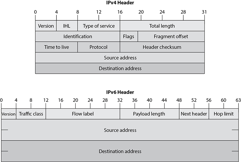
Figure 4-16 IPv4 vs. IPv6 headers
The 6to4 and Teredo are intersite tunneling mechanisms, and ISATAP is an intrasite mechanism. So the first two are used for connectivity between different networks, and ISATAP is used for connectivity of systems within a specific network. Notice in Figure 4-17 that 6to4 and Teredo are used on the Internet and ISATAP is used within an intranet.
While many of these automatic tunneling techniques reduce administration overhead, because network administrators do not have to configure each and every system and network device with two different IP addresses, there are security risks that need to be understood. Many times users and network administrators do not know that automatic tunneling capabilities are enabled, and thus they do not ensure that these different tunnels are secured and/or are being monitored. If you are an administrator of a network and have intrusion detection systems (IDSs), intrusion prevention systems (IPSs), and firewalls that are only configured to monitor and restrict IPv4 traffic, then all IPv6 traffic could be traversing your network insecurely. Attackers use these protocol tunnels and misconfigurations to get past these types of security devices so that malicious activities can take place unnoticed. If you are a user and have a host-based firewall that only understands IPv4 and your operating system has a dual IPv4/IPv6 networking stack, traffic could be bypassing your firewall without being monitored and logged. The use of Teredo can actually open ports in NAT devices that allow for unintended traffic in and out of a network. It is critical that people who are responsible for configuring and maintaining systems and networks understand the differences between IPv4 and IPv6 and how the various tunneling mechanisms work so that all vulnerabilities are identified and properly addressed. Products and software may need to be updated to address both traffic types, proxies may need to be deployed to manage traffic communication securely, IPv6 should be disabled if not needed, and security appliances need to be configured to monitor all traffic types.
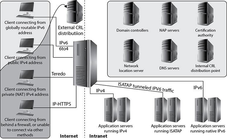
Figure 4-17 Various IPv4 to IPv6 tunneling techniques
Layer 2 Security Standards
As frames pass from one network device to another device, attackers could sniff the data; modify the headers; redirect the traffic; spoof traffic; carry out man-in-the-middle attacks, DoS attacks, and replay attacks; and indulge in other malicious activities. It has become necessary to secure network traffic at the frame level, which is layer 2 of the OSI model.
802.1AE is the IEEE MAC Security standard (MACSec), which defines a security infrastructure to provide data confidentiality, data integrity, and data origin authentication. Where a virtual private network (VPN) connection provides protection at the higher networking layers, MACSec provides hop-by-hop protection at layer 2, as shown in Figure 4-18.
MACSec integrates security protection into wired Ethernet networks to secure LAN-based traffic. Only authenticated and trusted devices on the network can communicate with each other. Unauthorized devices are prevented from communicating via the network, which helps prevent attackers from installing rogue devices and redirecting traffic between nodes in an unauthorized manner. When a frame arrives at a device that is configured with MACSec, the MACSec Security Entity (SecY) decrypts the frame if necessary and computes an integrity check value (ICV) on the frame and compares it with the ICV that was sent with the frame. If the ICVs match, the device processes the frame. If they do not match, the device handles the frame according to a preconfigured policy, such as discarding it.

Figure 4-18 MACSec provides layer 2 frame protection.
The IEEE 802.1AR standard specifies unique per-device identifiers (DevID) and the management and cryptographic binding of a device (router, switch, access point) to its identifiers. A verifiable unique device identity allows establishment of the trustworthiness of devices, and thus facilitates secure device provisioning.
As a security administrator you really only want devices that are allowed on your network to be plugged into your network. But how do you properly and uniquely identify devices? The manufacture serial number is not available for a protocol to review. MAC, hostnames, and IP addresses are easily spoofed. 802.1AR defines a globally unique per-device secure identifier cryptographically bound to the device through the use of public cryptography and digital certificates. These unique hardware-based credentials can be used with the Extensible Authentication Protocol-Transport Layer Security (EAP-TLS) authentication framework. Each device that is compliant with IEEE 802.1AR comes with a single built-in initial secure device identity (iDevID). The iDevID is an instance of the general concept of a DevID, which is intended to be used with authentication protocols such as EAP, which is supported by IEEE 802.1X.
So 802.1AR provides a unique ID for a device. 802.1AE provides data encryption, integrity, and origin authentication functionality. 802.1AF carries out key agreement functions for the session keys used for data encryption. Each of these standards provides specific parameters to work within an 802.1X EAP-TLS framework, as shown in Figure 4-19.

Figure 4-19 Layer 2 security protocols
As Figure 4-19 shows, when a new device is installed on the network, it cannot just start communicating with other devices, receive an IP address from a Dynamic Host Configuration Protocol (DHCP) server, resolve names with the DNS server, etc. The device cannot carry out any network activity until it is authorized to do so. So 802.1X port authentication kicks in, which means that only authentication data is allowed to travel from the new device to the authenticating server. The authentication data is the digital certificate and hardware identity associated with that device (802.1AR), which is processed by EAP-TLS. Once the device is authenticated, usually by a Remote Authentication Dial-In User Server (RADIUS) server, encryption keying material is negotiated and agreed upon between surrounding network devices. Once the keying material is installed, then data encryption and frame integrity checking can take place (802.1AE) as traffic goes from one network device to the next.
These IEEE standards are new and evolving and at different levels of implementation by various vendors. One way the unique hardware identity and cryptographic material are embedded in new network devices is through the use of a Trusted Platform Module (TPM; described in Chapter 3).
Converged Protocols
Converged protocols are those that started off independent and distinct from one another but over time converged to become one. How is this possible? Think about the phone and data networks. Once upon a time, these were two different entities and each had its own protocols and transmission media. For a while, in the 1990s, data networks sometimes rode over voice networks using data modems. This was less than ideal, which is why we flipped it around and started using data networks as the carrier for voice communications. Over time, the voice protocols converged onto the data protocols, which paved the way for Voice over IP (VoIP).
Technically, the term converged implies that the two protocols became one. Oftentimes, however, the term is used to describe cases in which one protocol was originally independent of another, but over time started being encapsulated (or tunneled) within that other one. The following are examples of converged protocols:
• Fibre Channel over Ethernet (FCoE) This is a protocol encapsulation that allows Fibre Channel (FC) frames to ride over Ethernet networks. FC was developed by ANSI in 1988 as a way to connect supercomputers using optical fibers. Nowadays FCoE is used in some storage area networks (SANs), but is not common.
• Multiprotocol Label Switching (MPLS) MPLS was originally developed to improve routing performance, but is frequently used for its ability to create VPNs over a variety of layer 2 protocols. It has elements of both layer 2 (data link) and layer 3 (networking), and so is commonly referred to as a layer 2.5 protocol. MPLS is considered a converged protocol because it can encapsulate any higher-layer protocol and tunnel it over a variety of links.
• Internet Small Computer System Interface (iSCSI) iSCSI encapsulates SCSI data in TCP segments. SCSI is a set of technologies that allows peripherals to be connected to computers. The problem with the original SCSI was that it has limited range, which means that connecting a remote peripheral (e.g., camera or storage device) is not normally possible. The solution was to let SCSI ride on TCP segments so a peripheral device could be literally anywhere in the world and still appear as local to a computer.
IP convergence, which addresses a specific type of converged protocols, is the transition of services from disparate transport media and protocols to IP. The earlier example of VoIP is also a case of IP convergence. It is not hard to see that IP has emerged as the dominant standard for networking, so it makes sense that any new protocols would leverage this existing infrastructure rather than create a separate one.
Transmission Media
We’ve talked a fair bit about the protocols that allow us to move data from point A to point B, but we haven’t really covered what it is that carries this information. A transmission medium is a physical thing through which data is moved. If we are speaking with each other, our vocal chords create vibrations in the air that we expel from our lungs, in which case the air is the transmission medium. Broadly speaking, we use three different types of transmission media: electrical wires, optical fibers, and free space.
• Electrical wires encode information as changes in the voltage level of an electric current. Typically, we use cables, which are two or more wires encased within a sheath.
• Optical fibers transmit data that is encoded in the wavelength (color), phase, or polarization of the light. The light is generated by either an LED or a laser diode. As with electrical wires, we usually bundle multiple fibers into cables for longer distances.
• Free space is the medium we use for wireless communications. Any electromagnetic signal can travel through it even outside our atmosphere. We tend to use mostly radio signals in free space, but every now and then you may find a system that uses light, such as infrared laser beams.
Types of Transmission
Physical data transmission can happen in different ways (analog or digital); can use different synchronization schemes (synchronous or asynchronous); can use either one sole channel over a transmission medium (baseband) or several different channels over a transmission medium (broadband); and can take place as electrical voltage, radio wave, or optical signals. These transmission types and their characteristics are described in the following sections.
Analog and Digital
A signal is just some way of moving information in a physical format from one point to another point. You can signal a message to another person through nodding your head, waving your hand, or giving a wink. Somehow you are transmitting data to that person through your signaling method. In the world of technology, we have specific carrier signals that are in place to move data from one system to another system. The carrier signal is like a horse, which takes a rider (data) from one place to another place. Data can be transmitted through analog or digital signaling formats. If you are moving data through an analog transmission technology (e.g., radio), then the data is represented by the characteristics of the waves that are carrying it. For example, a radio station uses a transmitter to put its data (music) onto a radio wave that will travel all the way to your antenna. The information is stripped off by the receiver in your radio and presented to you in its original format—a song. The data is encoded onto the carrier signal and is represented by various amplitude and frequency values, as shown in Figure 4-20.
Data being represented in wave values (analog) is different from data being represented in discrete voltage values (digital). As an analogy, compare an analog clock and a digital clock. An analog clock has hands that continuously rotate on the face of the clock. To figure out what time it is, you have to interpret the position of the hands and map their positions to specific values. So you have to know that if the small hand is on the number 1 and the large hand is on the number 6, this actually means 1:30. The individual and specific location of the hands corresponds to a value. A digital clock does not take this much work. You just look at it and it gives you a time value in the format of number:number. There is no mapping work involved with a digital clock because it provides you with data in clear-cut formats.
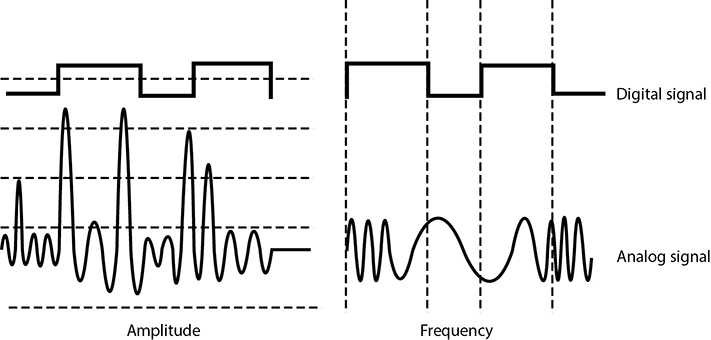
Figure 4-20 Analog signals are measured in amplitude and frequency, whereas digital signals represent binary digits as electrical pulses.
An analog clock can represent different values as the hands move forward—1:35 and 1 second, 1:35 and 2 seconds, 1:35 and 3 seconds. Each movement of the hands represents a specific value just like the individual data points on a wave in an analog transmission. A digital clock provides discrete values without having to map anything. The same is true with digital transmissions: the value is always either a 1 or a 0—no need for mapping to find the actual value.
Computers have always worked in a binary and digital manner (1 or 0). When our telecommunication infrastructure was purely analog, each system that needed to communicate over a telecommunication line had to have a modem (modulator/demodulator), which would modulate the digital data into an analog signal. The sending system’s modem would modulate the data on to the signal, and the receiving system’s modem would demodulate the data off the signal.
Digital signals are more reliable than analog signals over a long distance and provide a clear-cut and efficient signaling method because the voltage is either on (1) or not on (0), compared to interpreting the waves of an analog signal. Extracting digital signals from a noisy carrier is relatively easy. It is difficult to extract analog signals from background noise because the amplitudes and frequencies of the waves slowly lose form. This is because an analog signal could have an infinite number of values or states, whereas a digital signal exists in discrete states. A digital signal is a square wave, which does not have all of the possible values of the different amplitudes and frequencies of an analog signal. Digital systems can implement compression mechanisms to increase data throughput, provide signal integrity through repeaters that “clean up” the transmissions, and multiplex different types of data (voice, data, video) onto the same transmission channel. As we will see in following sections, most telecommunication technologies have moved from analog to digital transmission technologies.
EXAM TIP Bandwidth refers to the number of electrical pulses that can be transmitted over a link within a second, and these electrical pulses carry individual bits of information. Bandwidth is the data transfer capability of a connection and is commonly associated with the amount of available frequencies and speed of a link. Data throughput is the actual amount of data that can be carried over this connection. Data throughput values can be higher than bandwidth values if compression mechanisms are implemented. But if links are highly congested or there are interference issues, the data throughput values can be lower. Both bandwidth and data throughput are measured in bits per second.
Asynchronous and Synchronous
Analog and digital transmission technologies deal with the characteristics of the physical carrier on which data is moved from one system to another. Asynchronous and synchronous transmission types are similar to the cadence rules we use for conversation synchronization. Asynchronous and synchronous network technologies provide synchronization rules to govern how systems communicate to each other. If you have ever spoken over a satellite phone, you have probably experienced problems with communication synchronization. You and the other person talking do not allow for the necessary delay that satellite communication requires, so you “speak over” one another. Once you figure out the delay in the connection, you resynchronize your timing so that only one person’s data (voice) is transmitting at one time so that each person can properly understand the full conversation. Proper pauses frame your words in a way to make them understandable.
Synchronization through communication also happens when we write messages to each other. Properly placed commas, periods, and semicolons provide breaks in text so that the person reading the message can better understand the information. If you see “stickwithmekidandyouwillweardiamonds” without the proper punctuation, it is more difficult for you to understand. This is why we have grammar rules. If someone writes you a letter starting from the bottom and right side of a piece of paper and you do not know this, you will not be able to read his message properly.
Technological communication protocols also have their own grammar and synchronization rules when it comes to the transmission of data. If two systems are communicating over a network protocol that employs asynchronous timing, then start and stop bits are used. The sending system sends a “start” bit, then sends its character, and then sends a “stop” bit. This happens for the whole message. The receiving system knows when a character is starting and stopping; thus, it knows how to interpret each character of the message. This is akin to our previous example of using punctuation marks in written communications to convey pauses. If the systems are communicating over a network protocol that uses synchronous timing, then no start and stop bits are added. The whole message is sent without artificial breaks, but with a common timing signal that allows the receiver to know how to interpret the information without these bits. This is similar to our satellite phone example in which we use a timing signal (i.e., we count off seconds in our head) to ensure we don’t step all over the other person’s speech.
If two systems are going to communicate using a synchronous transmission technology, they do not use start and stop bits, but the synchronization of the transfer of data takes place through a timing sequence, which is initiated by a clock pulse.
It is the data link protocol that has the synchronization rules embedded into it. So when a message goes down a system’s network stack, if a data link protocol, such as High-level Data Link Control (HDLC, described later in the chapter), is being used, then a clocking sequence is in place. (The receiving system has to also be using this protocol so it can interpret the data.) If the message is going down a network stack and a protocol such as Asynchronous Transfer Mode (ATM) is at the data link layer, then the message is framed with start and stop indicators.
Data link protocols that employ synchronous timing mechanisms are commonly used in environments that have systems that transfer large amounts of data in a predictable manner (i.e., mainframe environment). Environments that contain systems that send data in a nonpredictable manner (i.e., Internet connections) commonly have systems with protocols that use asynchronous timing mechanisms.
So, synchronous communication protocols transfer data as a stream of bits instead of framing it in start and stop bits. The synchronization can happen between two systems using a clocking mechanism, or a signal can be encoded into the data stream to let the receiver synchronize with the sender of the message. This synchronization needs to take place before the first message is sent. The sending system can transmit a digital clock pulse to the receiving system, which translates into, “We will start here and work in this type of synchronization scheme.” Many modern bulk communication systems, such as high-bandwidth satellite links, use Global Positioning System (GPS) clock signals to synchronize their communications without the need to include a separate channel for timing.
Broadband and Baseband
So analog transmission means that data is being moved as waves, and digital transmission means that data is being moved as discrete electric pulses. Synchronous transmission means that two devices control their conversations with a clocking mechanism, and asynchronous means that systems use start and stop bits for communication synchronization. Now let’s look at how many individual communication sessions can take place at one time.
A baseband technology uses the entire communication channel for its transmission, whereas a broadband technology divides the communication channel into individual and independent subchannels so that different types of data can be transmitted simultaneously. Baseband permits only one signal to be transmitted at a time, whereas broadband carries several signals over different subchannels. For example, a coaxial cable TV (CATV) system is a broadband technology that delivers multiple television channels over the same cable. This system can also provide home users with Internet access, but this data is transmitted at a different frequency range than the TV channels.
As an analogy, baseband technology only provides a one-lane highway for data to get from one point to another point. A broadband technology provides a data highway made up of many different lanes, so that not only can more data be moved from one point to another point, but different types of data can travel over the individual lanes.
Any transmission technology that “chops up” one communication channel into multiple channels is considered broadband. The communication channel is usually a specific range of frequencies, and the broadband technology provides delineation between these frequencies and techniques on how to modulate the data onto the individual subchannels. To continue with our analogy, we could have one large highway that could fit eight individual lanes—but unless we have something that defines these lanes and there are rules for how these lanes are used, this is a baseband connection. If we take the same highway and lay down painted white lines, traffic signs, on and off ramps, and rules that drivers have to follow, now we are talking about broadband.
A digital subscriber line (DSL) uses one single phone line and constructs a set of high-frequency channels for Internet data transmissions. A cable modem uses the available frequency spectrum that is provided by a cable TV carrier to move Internet traffic to and from a household. Mobile broadband devices implement individual channels over a cellular connection, and Wi-Fi broadband technology moves data to and from an access point over a specified frequency set. We will cover these technologies in more depth throughout the chapter, but for now you just need to understand that they are different ways of cutting up one channel into individual channels for higher data transfer and that they provide the capability to move different types of traffic at the same time.
Next, let’s look at the different ways we connect the many devices that make up small and large networks around the world.
Cabling
Electrical signals travel as currents through cables and can be negatively affected by many factors within the environment, such as motors, fluorescent lighting, magnetic forces, and other electrical devices. These items can corrupt the data as it travels through the cable, which is why cable standards are used to indicate cable type, shielding, transmission rates, and maximum distance a particular type of cable can be used.
Cabling has bandwidth values associated with it, which is different from data throughput values. Although these two terms are related, they are indeed different. The bandwidth of a cable indicates the highest frequency range it uses—for instance, 10Base-T uses 10 MHz, 100Base-TX uses 80 MHz, and 1000Base-T uses 100 MHz. This is different from the actual amount of data that can be pushed through a cable. The data throughput rate is the actual amount of data that goes through the wire after compression and encoding have been used. 10Base-T has a data rate of 10 Mbps, 100Base-TX has a data rate of 100 Mbps, and 1000Base-T has a data rate of 1 Gbps. The bandwidth can be thought of as the size of the pipe, and the data throughput rate is the actual amount of data that travels per second through that pipe.
Bandwidth is just one of the characteristics we will look at as we cover various cabling types in the following sections.
Coaxial Cable
Coaxial cable has a copper core that is surrounded by a shielding layer and grounding wire, as shown in Figure 4-21. This is all encased within a protective outer jacket. Compared to twisted-pair cable, coaxial cable is more resistant to electromagnetic interference (EMI), provides a higher bandwidth, and supports the use of longer cable lengths. So, why is twisted-pair cable more popular? Twisted-pair cable is cheaper and easier to work with, and the move to switched environments that provide hierarchical wiring schemes has overcome the cable-length issue of twisted-pair cable.
Coaxial cabling is used as a transmission line for radio frequency signals. If you have cable TV, you have coaxial cabling entering your house and the back of your TV. The various TV channels are carried over different radio frequencies. We will cover cable modems later in this chapter, which is a technology that allows you to use some of the “empty” TV frequencies for Internet connectivity.
Twisted-Pair Cable
Twisted-pair cabling has insulated copper wires surrounded by an outer protective jacket. If the cable has an outer foil shielding, it is referred to as shielded twisted pair (STP), which adds protection from radio frequency interference (RFI) and EMI. Twisted-pair cabling, which does not have this extra outer shielding, is called unshielded twisted pair (UTP).
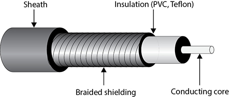
Figure 4-21 Coaxial cable
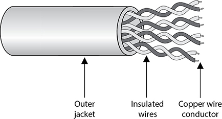
Figure 4-22 Twisted-pair cabling uses copper wires.
The twisted-pair cable contains copper wires that twist around each other, as shown in Figure 4-22. This twisting of the wires protects the integrity and strength of the signals they carry. Each wire forms a balanced circuit, because the voltage in each pair uses the same amplitude, just with opposite phases. The tighter the twisting of the wires, the more resistant the cable is to interference and attenuation. UTP has several categories of cabling, each of which has its own unique characteristics.
The twisting of the wires, the type of insulation used, the quality of the conductive material, and the shielding of the wire determine the rate at which data can be transmitted. The UTP ratings indicate which of these components were used when the cables were manufactured. Some types are more suitable and effective for specific uses and environments. Table 4-3 lists the cable ratings.
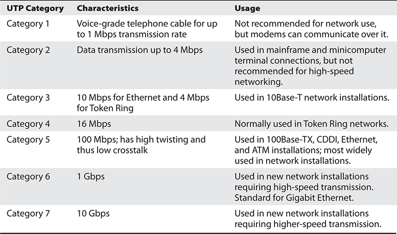
Table 4-3 UTP Cable Ratings
Copper cable has been around for many years. It is inexpensive and easy to use. A majority of the telephone systems today use copper cabling with the rating of voice grade. Twisted-pair wiring is the preferred network cabling, but it also has its drawbacks. Copper actually resists the flow of electrons, which causes a signal to degrade after it has traveled a certain distance. This is why cable lengths are recommended for copper cables; if these recommendations are not followed, a network could experience signal loss and data corruption. Copper also radiates energy, which means information can be monitored and captured by intruders. UTP is the least secure networking cable compared to coaxial and fiber. If a company requires higher speed, higher security, and cables to have longer runs than what is allowed in copper cabling, fiber-optic cable may be a better choice.
Fiber-Optic Cable
Twisted-pair cable and coaxial cable use copper wires as their data transmission media, but fiber-optic cable uses a type of glass that carries light waves, which represent the data being transmitted. The glass core is surrounded by a protective cladding, which in turn is encased within an outer jacket.
Because it uses glass, fiber-optic cabling has higher transmission speeds that allow signals to travel over longer distances. Fiber cabling is not as affected by attenuation and EMI when compared to cabling that uses copper. It does not radiate signals, as does UTP cabling, and is difficult to eavesdrop on; therefore, fiber-optic cabling is much more secure than UTP, STP, or coaxial.
Using fiber-optic cable sounds like the way to go, so you might wonder why you would even bother with UTP, STP, or coaxial. Unfortunately, fiber-optic cable is expensive and difficult to work with. It is usually used in backbone networks and environments that require high data transfer rates. Most networks use UTP and connect to a backbone that uses fiber.
NOTE The price of fiber and the cost of installation have been steadily decreasing, while the demand for more bandwidth only increases. More organizations and service providers are installing fiber directly to the end user.
Cabling Problems
Cables are extremely important within networks, and when they experience problems, the whole network could experience problems. This section addresses some of the more common cabling issues many networks experience.
Noise Noise on a line is usually caused by surrounding devices or by characteristics of the wiring’s environment. Noise can be caused by motors, computers, copy machines, fluorescent lighting, and microwave ovens, to name a few. This background noise can combine with the data being transmitted over the cable and distort the signal, as shown in Figure 4-23. The more noise there is interacting with the cable, the more likely the receiving end will not receive the data in the form originally transmitted.
Attenuation Attenuation is the loss of signal strength as it travels. This is akin to rolling a ball down the floor; as it travels, air causes resistance that slows it down and eventually stops it. In the case of electricity, the metal in the wire also offers resistance to the flow of electricity. Though some materials such as copper and gold offer very little resistance, it is still there. The longer a wire, the more attenuation occurs, which causes the signal carrying the data to deteriorate. This is why standards include suggested cable-run lengths.
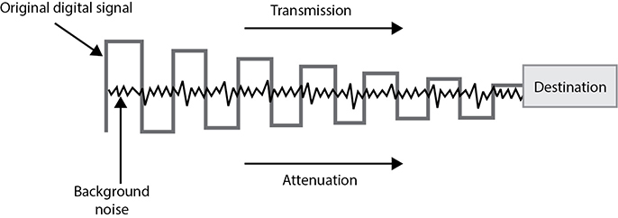
Figure 4-23 Background noise can merge with an electronic signal and alter the signal’s integrity.
The effects of attenuation increase with higher frequencies; thus, 100Base-TX at 80 MHz has a higher attenuation rate than 10Base-T at 10 MHz. This means that cables used to transmit data at higher frequencies should have shorter cable runs to ensure attenuation does not become an issue.
If a networking cable is too long, attenuation will become a problem. Basically, the data is in the form of electrons, and these electrons have to “swim” through a copper wire. However, this is more like swimming upstream, because there is a lot of resistance on the electrons working in this media. After a certain distance, the electrons start to slow down and their encoding format loses form. If the form gets too degraded, the receiving system cannot interpret them any longer. If a network administrator needs to run a cable longer than its recommended segment length, she needs to insert a repeater or some type of device that will amplify the signal and ensure it gets to its destination in the right encoding format.
Attenuation can also be caused by cable breaks and malfunctions. This is why cables should be tested. If a cable is suspected of attenuation problems, cable testers can inject signals into the cable and read the results at the end of the cable.
Crosstalk Crosstalk is a phenomenon that occurs when electrical signals of one wire spill over to the signals of another wire. When electricity flows through a wire, it generates a magnetic field around it. If another wire is close enough, the second wire acts as an antenna that turns this magnetic field into an electric current. When the different electrical signals mix, their integrity degrades and data corruption can occur. UTP is much more vulnerable to crosstalk than STP or coaxial because it does not have extra layers of shielding to help protect against it.
Fire Rating of Cables Just as buildings must meet certain fire codes, so must wiring schemes. A lot of companies string their network wires in drop ceilings—the space between the ceiling and the next floor—or under raised floors. This hides the cables and prevents people from tripping over them. However, when wires are strung in places like this, they are more likely to catch on fire without anyone knowing about it. Some cables produce hazardous gases when on fire that would spread throughout the building quickly. Network cabling that is placed in these types of areas, called plenum space, must meet a specific fire rating to ensure it will not produce and release harmful chemicals in case of a fire. A ventilation system’s components are usually located in this plenum space, so if toxic chemicals were to get into that area, they could easily spread throughout the building in minutes.
Nonplenum cables usually have a polyvinyl chloride (PVC) jacket covering, whereas plenum-rated cables have jacket covers made of fluoropolymers. When setting up a network or extending an existing network, it is important you know which wire types are required in which situation.
Cables should be installed in unexposed areas so they are not easily tripped over, damaged, or eavesdropped upon. The cables should be strung behind walls and in the protected spaces as in dropped ceilings. In environments that require extensive security, wires can be encapsulated within pressurized conduits so if someone attempts to access a wire, the pressure of the conduit will change, causing an alarm to sound and a message to be sent to the security staff. A better approach to high-security requirements is probably to use fiber-optic cable, which is much more difficult to covertly tap.
NOTE While a lot of the world’s infrastructure is wired and thus uses one of these types of cables, remember that a growing percentage of our infrastructure is not wired, but rather uses some form of wireless technology (Bluetooth, Wi-Fi, satellite, etc.) particularly to reach end devices.
Wireless Networks
Wireless communications take place much more often than we think, and a wide range of broadband wireless data transmission technologies are used in various frequency ranges. Broadband wireless signals occupy frequency bands that may be shared with microwave, satellite, radar, and ham radio use, for example. We use these technologies for television transmissions, cellular phones, satellite transmissions, spying, surveillance, and garage door openers. As we will see in the next sections, wireless communication takes place over personal area networks; wireless LANs, MANs, and WANs; and via satellite. Each is illustrated in Figure 4-24.
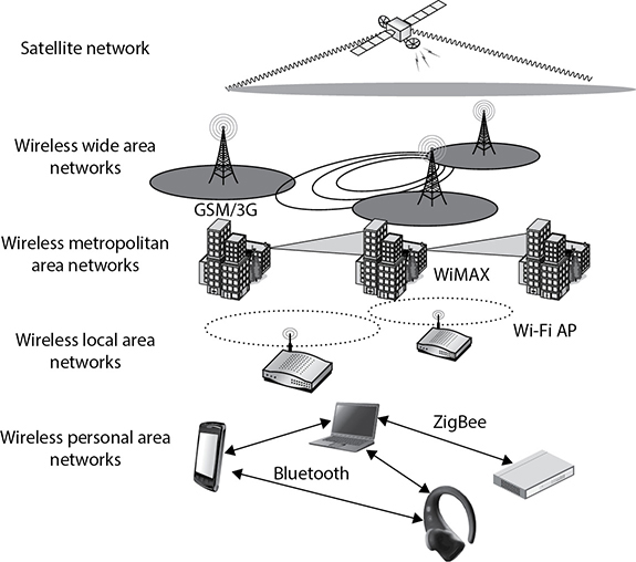
Figure 4-24 Various wireless transmission types
Wireless Communications Techniques
Wireless communication involves transmitting information via radio waves that move through air and space. These signals can be described in a number of ways, but normally are described in terms of frequency and amplitude. The frequency of a signal dictates the amount of data that can be carried and how far. The higher the frequency, the more data the signal can carry, but the higher the frequency, the more susceptible the signal is to atmospheric interference. Normally, a higher frequency can carry more data, but over a shorter distance.
In a wired network, each computer and device has its own cable connecting it to the network in some fashion. In wireless technologies, each device must instead share the allotted radio frequency spectrum with all other wireless devices that need to communicate. This spectrum of frequencies is finite in nature, which means it cannot grow if more and more devices need to use it. The same thing happens with Ethernet—all the computers on a segment share the same medium, and only one computer can send data at any given time. Otherwise, a collision can take place. Wired networks using Ethernet employ the CSMA/CD (collision detection) technology. Wireless LAN (WLAN) technology is actually very similar to Ethernet, but it uses CSMA/CA (collision avoidance). The wireless device sends out a broadcast indicating it is going to transmit data. This is received by other devices on the shared medium, which causes them to hold off on transmitting information. It is all about trying to eliminate or reduce collisions. (The two versions of CSMA are explained later in this chapter in the section “CSMA.”)
A number of techniques have been developed to allow wireless devices to access and share this limited amount of medium for communication purposes. We will look at different types of spread spectrum techniques in the next sections. The goal of each of these wireless technologies is to split the available frequency into usable portions, since it is a limited resource, and to allow the devices to share them efficiently.
Spread Spectrum
In the world of wireless communications, certain technologies and industries are allocated specific spectrums, or frequency ranges, to be used for transmissions. In the United States, the Federal Communications Commission (FCC) decides upon this allotment of frequencies and enforces its own restrictions. Spread spectrum means that something is distributing individual signals across the allocated frequencies in some fashion. So when a spread spectrum technology is used, the sender spreads its data across the frequencies over which it has permission to communicate. This allows for more effective use of the available bandwidth, because the sending system can use more than one frequency at a time.
Think of it in terms of investments. In conventional radio transmissions, all the data bits are modulated onto a single carrier wave that operates on a specific frequency (as in amplitude modulated [AM] radio systems) or on a narrow band of frequencies (as in frequency modulated [FM] radio). This is akin to investing only in one stock; it is simple and efficient, but may not be ideal in risky environments. The alternative is to diversify your portfolio, which is normally done by investing a bit of your money in each of many stocks across a wide set of industries. This is more complex and inefficient, but can save your bottom line when one of your companies takes a nose-dive. This example is akin to direct sequence spread spectrum (DSSS), which we discuss in an upcoming section. There is in theory another way to minimize your exposure to volatile markets. Suppose the cost of buying and selling was negligible. You could then invest all your money in a single stock, but only for a brief period of time, sell it as soon as you turn a profit, and then reinvest all your proceeds in another stock. By jumping around the market, your exposure to the problems of any one company are minimized. This approach would be comparable to frequency hopping spread spectrum (FHSS). The point is that spread-spectrum communications are used primarily to reduce the effects of adverse conditions such as crowded radio bands, interference, and eavesdropping.
Frequency Hopping Spread Spectrum Frequency hopping spread spectrum (FHSS) takes the total amount of bandwidth (spectrum) and splits it into smaller subchannels. The sender and receiver work at one of these subchannels for a specific amount of time and then move to another subchannel. The sender puts the first piece of data on one frequency, the second on a different frequency, and so on. The FHSS algorithm determines the individual frequencies that will be used and in what order, and this is referred to as the sender and receiver’s hop sequence.
Interference is a large issue in wireless transmissions because it can corrupt signals as they travel. Interference can be caused by other devices working in the same frequency space. The devices’ signals step on each other’s toes and distort the data being sent. The FHSS approach to this is to hop between different frequencies so that if another device is operating at the same frequency, it will not be drastically affected. Consider another analogy: Suppose George and Marge have to work in the same room. They could get into each other’s way and affect each other’s work. But if they periodically change rooms, the probability of them interfering with each other is reduced.
A hopping approach also makes it much more difficult for eavesdroppers to listen in on and reconstruct the data being transmitted when used in technologies other than WLAN. FHSS has been used extensively in military wireless communications devices because the only way the enemy could intercept and capture the transmission is by knowing the hopping sequence. The receiver has to know the sequence to be able to obtain the data. But in today’s WLAN devices, the hopping sequence is known and does not provide any security.
So how does this FHSS stuff work? The sender and receiver hop from one frequency to another based on a predefined hop sequence. Several pairs of senders and receivers can move their data over the same set of frequencies because they are all using different hop sequences. Let’s say you and Marge share a hop sequence of 1, 5, 3, 2, 4, and Nicole and Ed have a sequence of 4, 2, 5, 1, 3. Marge sends her first message on frequency 1, and Nicole sends her first message on frequency 4 at the same time. Marge’s next piece of data is sent on frequency 5, the next on 3, and so on until each reaches its destination, which is your wireless device. So your device listens on frequency 1 for a half-second, and then listens on frequency 5, and so on, until it receives all of the pieces of data that are on the line on those frequencies at that time. Ed’s device is listening to the same frequencies but at different times and in a different order, so his device ignores Marge’s message because it is out of sync with his predefined sequence. Without knowing the right code, Ed treats Marge’s messages as background noise and does not process them.
Direct Sequence Spread Spectrum Direct sequence spread spectrum (DSSS) takes a different approach by applying sub-bits to a message. The sub-bits are used by the sending system to generate a different format of the data before the data is transmitted. The receiving end uses these sub-bits to reassemble the signal into the original data format. The sub-bits are called chips, and the sequence of how the sub-bits are applied is referred to as the chipping code.
When the sender’s data is combined with the chip, the signal appears as random noise to anyone who does not know the chipping sequence. This is why the sequence is sometimes called a pseudo-noise sequence. Once the sender combines the data with the chipping sequence, the new form of the information is modulated with a radio carrier signal, and it is shifted to the necessary frequency and transmitted. What the heck does that mean? When using wireless transmissions, the data is actually moving over radio signals that work in specific frequencies. Any data to be moved in this fashion must have a carrier signal, and this carrier signal works in its own specific range, which is a frequency. So you can think of it this way: once the data is combined with the chipping code, it is put into a car (carrier signal), and the car travels down its specific road (frequency) to get to its destination.
The receiver basically reverses the process, first by demodulating the data from the carrier signal (removing it from the car). The receiver must know the correct chipping sequence to change the received data into its original format. This means the sender and receiver must be properly synchronized.
The sub-bits provide error-recovery instructions, just as parity does in RAID technologies. If a signal is corrupted using FHSS, it must be re-sent; but by using DSSS, even if the message is somewhat distorted, the signal can still be regenerated because it can be rebuilt from the chipping code bits. The use of this code allows for prevention of interference, allows for tracking of multiple transmissions, and provides a level of error correction.
FHSS vs. DSSS FHSS uses only a portion of the total bandwidth available at any one time, while the DSSS technology uses all of the available bandwidth continuously. DSSS spreads the signals over a wider frequency band, whereas FHSS uses a narrow band carrier that changes frequently across a wide band.
Since DSSS sends data across all frequencies at once, it has a higher data throughput than FHSS. The first wireless WAN standard, 802.11, used FHSS, but as bandwidth requirements increased, DSSS was implemented. By using FHSS, the 802.11 standard can provide a data throughput of only 1 to 2 Mbps. By using DSSS instead, 802.11b provides a data throughput of up to 11 Mbps.
Orthogonal Frequency-Division Multiplexing
The next step in trying to move even more data over wireless frequency signals came in the form of orthogonal frequency-division multiplexing (OFDM). OFDM is a digital multicarrier modulation scheme that compacts multiple modulated carriers tightly together, reducing the required bandwidth. The modulated signals are orthogonal (perpendicular) and do not interfere with each other. OFDM uses a composite of narrow channel bands to enhance its performance in high-frequency bands. OFDM is officially a multiplexing technology and not a spread spectrum technology, but is used in a similar manner.
A large number of closely spaced orthogonal subcarrier signals are used, and the data is divided into several parallel data streams or channels, one for each subcarrier. Channel equalization is simplified because OFDM uses many slowly modulated narrowband signals rather than one rapidly modulated wideband signal.
OFDM is used for several wideband digital communication types such as digital television, audio broadcasting, DSL broadband Internet access, wireless networks, and 4G mobile communications.
WLAN Components
A WLAN uses a transceiver, called an access point (AP), which connects to an Ethernet cable that is the link wireless devices use to access resources on the wired network, as shown in Figure 4-25. When the AP is connected to the LAN Ethernet by a wired cable, it is the component that connects the wired and the wireless worlds. The APs are in fixed locations throughout a network and work as communication beacons. Let’s say a wireless user has a device with a wireless NIC, which modulates her data onto radio frequency signals that are accepted and processed by the AP. The signals transmitted from the AP are received by the wireless NIC and converted into a digital format, which the device can understand.
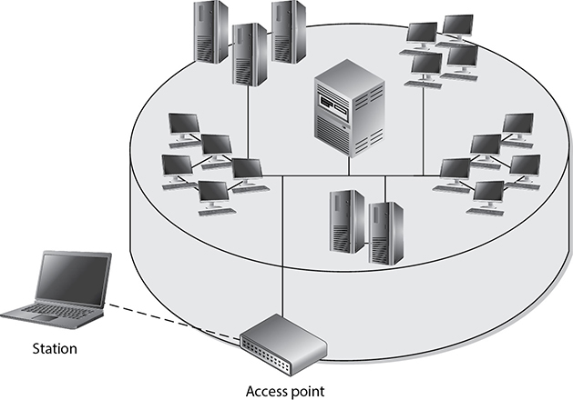
Figure 4-25 Access points allow wireless devices to participate in wired LANs.
When APs are used to connect wireless and wired networks, this is referred to as an infrastructure WLAN, which is used to extend an existing wired network. When there is just one AP and it is not connected to a wired network, it is considered to be in stand-alone mode and just acts as a wireless hub.
An ad hoc WLAN has no APs; the wireless devices communicate with each other through their wireless NICs instead of going through a centralized device. To construct an ad hoc network, wireless client software on contributing hosts and configured for peer-to-peer operation mode. Then, the user clicks Network in Windows Explorer and the software searches for other hosts operating in this similar mode and shows them to the user.
For a wireless device and AP to communicate, they must be configured to communicate over the same channel. A channel is a certain frequency within a given frequency band. The AP is configured to transmit over a specific channel, and the wireless device will “tune” itself to be able to communicate over this same frequency.
Any hosts that wish to participate within a particular WLAN must be configured with the proper Service Set ID (SSID). Various hosts can be segmented into different WLANs by using different SSIDs. The reasons to segment a WLAN into portions are the same reasons wired systems are segmented on a network: the users require access to different resources, have different business functions, or have different levels of trust.
NOTE When wireless devices work in infrastructure mode, the AP and wireless clients form a group referred to as a Basic Service Set (BSS). This group is assigned a name, which is the SSID value.
When WLAN technologies first came out, authentication was this simplistic—your device either had the right SSID value and WEP key or it did not. As wireless communication increased in use and many deficiencies were identified in these simplistic ways of authentication and encryption, many more solutions were developed and deployed.
Evolution of WLAN Security
To say that security was an afterthought in the first WLANs would be a remarkable understatement. As with many new technologies, wireless networks were often rushed to market with a focus on functionality, even if that sometimes came at the expense of security. Over time, vendors and standards bodies caught on and tried to correct these omissions. While we have made significant headway in securing our wireless networks, as security professionals we must acknowledge that whenever we transmit anything over the electromagnetic spectrum, we are essentially putting our data in the hands (or at least within the grasp) of our adversaries.
IEEE Standard 802.11
When wireless LANs (WLANs) were being introduced, there was industry-wide consensus that some measures would have to be taken to assure users that their data (now in the air) would be protected from eavesdropping to the same degree that data on a wired LAN was already protected. This was the genesis of Wired Equivalent Privacy (WEP). This first WLAN standard, codified as IEEE 802.11, had a tremendous number of security flaws. These were found within the core standard itself, as well as in different implementations of this standard. Before we delve into these, it will be useful to spend a bit of time with some of the basics of 802.11.
The wireless devices using this protocol can authenticate to the AP in two main ways: open system authentication (OSA) and shared key authentication (SKA). OSA does not require the wireless device to prove to the AP it has a specific cryptographic key to allow for authentication purposes. In many cases, the wireless device needs to provide only the correct SSID value. In OSA implementations, all transactions are in cleartext because no encryption is involved. So an intruder can sniff the traffic, capture the necessary steps of authentication, and walk through the same steps to be authenticated and associated to an AP.
When an AP is configured to use SKA, the AP sends a random value to the wireless device. The device encrypts this value with its cryptographic key and returns it. The AP decrypts and extracts the response, and if it is the same as the original value, the device is authenticated. In this approach, the wireless device is authenticated to the network by proving it has the necessary encryption key.
The three core deficiencies with WEP are the use of static encryption keys, the ineffective use of initialization vectors, and the lack of packet integrity assurance. The WEP protocol uses the RC4 algorithm, which is a stream-symmetric cipher. Symmetric means the sender and receiver must use the exact same key for encryption and decryption purposes. The 802.11 standard does not stipulate how to update these keys through an automated process, so in most environments, the RC4 symmetric keys are never changed out. And usually all of the wireless devices and the AP share the exact same key. This is like having everyone in your company use the exact same password. Not a good idea. So that is the first issue—static WEP encryption keys on all devices.
NOTE Cryptography topics are covered in detail in Chapter 3.
The next flaw is how initialization vectors (IVs) are used. An IV is a numeric seeding value that is used with the symmetric key and RC4 algorithm to provide more randomness to the encryption process. Randomness is extremely important in encryption because any patterns can give the bad guys insight into how the process works, which may allow them to uncover the encryption key that was used. The key and IV value are inserted into the RC4 algorithm to generate a key stream. The values (1’s and 0’s) of the key stream are XORed with the binary values of the individual packets. The result is ciphertext, or encrypted packets.
In most WEP implementations, the same IV values are used over and over again in this process, and since the same symmetric key (or shared secret) is generally used, there is no way to provide effective randomness in the key stream that is generated by the algorithm. The appearance of patterns allows attackers to reverse-engineer the process to uncover the original encryption key, which can then be used to decrypt future encrypted traffic.
So now we are onto the third mentioned weakness, which is the integrity assurance issue. WLAN products that use only the 802.11 standard introduce a vulnerability that is not always clearly understood. An attacker can actually change data within the wireless packets by flipping specific bits and altering the Integrity Check Value (ICV) so the receiving end is oblivious to these changes. The ICV works like a CRC function; the sender calculates an ICV and inserts it into a frame’s header. The receiver calculates his own ICV and compares it with the ICV sent with the frame. If the ICVs are the same, the receiver can be assured that the frame was not modified during transmission. If the ICVs are different, it indicates a modification did indeed take place and thus the receiver discards the frame. In WEP, there are certain circumstances in which the receiver cannot detect whether an alteration to the frame has taken place; thus, there is no true integrity assurance.
So the problems identified with the 802.11 standard include poor authentication, static WEP keys that can be easily obtained by attackers, IV values that are repetitive and do not provide the necessary degree of randomness, and a lack of data integrity. The next section describes the measures taken to remedy these problems.
CAUTION WEP is considered insecure and should not be used.
IEEE Standard 802.11i
IEEE came out with a standard in 2004 that deals with the security issues of the original 802.11 standard, which is called IEEE 802.11i or Wi-Fi Protected Access II (WPA2). Why the number 2? Because while the formal standard was being ratified by the IEEE, the Wi-Fi alliance pushed out WPA (the first one) based on the draft of the standard. For this reason, WPA is sometimes referred to as the draft IEEE 802.11i. This rush to push out WPA required the reuse of elements of WEP, which ultimately made WPA vulnerable to some of the same attacks that doomed its predecessor. Let’s start off by looking at WPA in depth, since this protocol is still widely used despite its weaknesses.
WPA employs different approaches that provide much more security and protection than the methods used in the original 802.11 standard. This enhancement of security is accomplished through specific protocols, technologies, and algorithms. The first protocol is Temporal Key Integrity Protocol (TKIP), which is backward-compatible with the WLAN devices based upon the original 802.11 standard. TKIP actually works with WEP by feeding it keying material, which is data to be used for generating new dynamic keys. TKIP generates a new key for every frame that is transmitted. WPA also integrates 802.1X port authentication and EAP authentication methods.
NOTE TKIP was developed by the IEEE 802.11i task group and the Wi-Fi Alliance. The goal of this protocol was to increase the strength of WEP or replace it fully without the need for hardware replacement. TKIP provides a key mixing function, which allows the RC4 algorithm to provide a higher degree of protection. It also provides a sequence counter to protect against replay attacks and implements a message integrity check mechanism.
The use of the 802.1X technology in the new 802.11i standard provides access control by restricting network access until full authentication and authorization have been completed, and provides a robust authentication framework that allows for different EAP modules to be plugged in. These two technologies (802.1X and EAP) work together to enforce mutual authentication between the wireless device and authentication server. So what about the static keys, IV value, and integrity issues?
TKIP addresses the deficiencies of WEP pertaining to static WEP keys and inadequate use of IV values. Two hacking tools, AirSnort and WEPCrack, can be used to easily crack WEP’s encryption by taking advantage of these weaknesses and the ineffective use of the key scheduling algorithm within the WEP protocol. If a company is using products that implement only WEP encryption and is not using a third-party encryption solution (such as a VPN), these programs can break its encrypted traffic within minutes. There is no “maybe” pertaining to breaking WEP’s encryption. Using these tools means it will be broken whether a 40-bit or 128-bit key is being used—it doesn’t matter. This is one of the most serious and dangerous vulnerabilities pertaining to the original 802.11 standard.
The use of TKIP provides the ability to rotate encryption keys to help fight against these types of attacks. The protocol increases the length of the IV value and ensures each and every frame has a different IV value. This IV value is combined with the transmitter’s MAC address and the original WEP key, so even if the WEP key is static, the resulting encryption key will be different for each and every frame. (WEP key + IV value + MAC address = new encryption key.) So what does that do for us? This brings more randomness to the encryption process, and it is randomness that is necessary to properly thwart cryptanalysis and attacks on cryptosystems. The changing IV values and resulting keys make the resulting key stream less predictable, which makes it much harder for the attacker to reverse-engineer the process and uncover the original key.
TKIP also deals with the integrity issues by using a MIC instead of an ICV function. If you are familiar with a message authentication code (MAC) function, this is the same thing. A symmetric key is used with a hashing function, which is similar to a CRC function but stronger. The use of MIC instead of ICV ensures the receiver will be properly alerted if changes to the frame take place during transmission. The sender and receiver calculate their own separate MIC values. If the receiver generates a MIC value different from the one sent with the frame, the frame is seen as compromised and it is discarded.
The types of attacks that have been carried out on WEP devices and networks that just depend upon WEP are numerous and unnerving. Wireless traffic can be easily sniffed, data can be modified during transmission without the receiver being notified, rogue APs can be erected (which users can authenticate to and communicate with, not knowing it is a malicious entity), and encrypted wireless traffic can be decrypted quickly and easily. Unfortunately, these vulnerabilities usually provide doorways to the actual wired network where the more destructive attacks can begin.
The full 802.11i (WPA2) has a major advantage over WPA by providing encryption protection with the use of the AES algorithm in counter mode with CBC-MAC (CCM), which is referred to as the Counter Mode Cipher Block Chaining Message Authentication Code Protocol (CCM Protocol or CCMP). AES is a more appropriate algorithm for wireless than RC4 and provides a higher level of protection. WPA2 defaults to CCMP, but can switch down to TKIP and RC4 to provide backward compatibility with WPA devices and networks.
NOTE CBC, CCM, and CCMP modes are explained in Chapter 3.
IEEE Standard 802.1X
The 802.11i standard can be understood as three main components in two specific layers. The lower layer contains the improved encryption algorithms and techniques (TKIP and CCMP), while the layer that resides on top of it contains 802.1X. They work together to provide more layers of protection than the original 802.11 standard.
We covered 802.1X earlier in the chapter, but let’s cover it more in depth here. The 802.1X standard is a port-based network access control that ensures a user cannot make a full network connection until he is properly authenticated. This means a user cannot access network resources and no traffic is allowed to pass, other than authentication traffic, from the wireless device to the network until the user is properly authenticated. An analogy is having a chain on your front door that enables you to open the door slightly to identify a person who knocks before you allow him to enter your house.
NOTE 802.1X is not a wireless protocol. It is an access control protocol that can be implemented on both wired and wireless networks.
By incorporating 802.1X, the new standard allows for the user to be authenticated, whereas using only WEP provides system authentication. User authentication provides a higher degree of confidence and protection than system authentication.
The 802.1X technology actually provides an authentication framework and a method of dynamically distributing encryption keys. The three main entities in this framework are the supplicant (wireless device), the authenticator (AP), and the authentication server (usually a RADIUS server).
The AP controls all communication and allows the wireless device to communicate with the authentication server and wired network only when all authentication steps are completed successfully. This means the wireless device cannot send or receive HTTP, DHCP, SMTP, or any other type of traffic until the user is properly authorized. WEP does not provide this type of strict access control.
Another disadvantage of the original 802.11 standard is that mutual authentication is not possible. When using WEP alone, the wireless device can authenticate to the AP, but the authentication server is not required to authenticate to the wireless device. This means a rogue AP can be set up to capture users’ credentials and traffic without the users being aware of this type of attack. 802.11i deals with this issue by using EAP. EAP allows for mutual authentication to take place between the authentication server and wireless device, and provides flexibility in that users can be authenticated by using passwords, tokens, one-time passwords, certificates, smart cards, or Kerberos. This allows wireless users to be authenticated using the current infrastructure’s existing authentication technology. The wireless device and authentication server that are 802.11i-compliant have different authentication modules that plug into 802.1X to allow for these different options. So, 802.1X provides the framework that allows for the different EAP modules to be added by a network administrator. The two entities (supplicant and authenticator) agree upon one of these authentication methods (EAP modules) during their initial handshaking process.
The 802.11i standard does not deal with the full protocol stack, but addresses only what is taking place at the data link layer of the OSI model. Authentication protocols reside at a higher layer than this, so 802.11i does not specify particular authentication protocols. The use of EAP, however, allows different protocols to be used by different vendors. For example, Cisco uses a purely password-based authentication framework called Lightweight Extensible Authentication Protocol (LEAP). Other vendors, including Microsoft, use EAP and Transport Layer Security (EAP-TLS), which carries out authentication through digital certificates. And yet another choice is Protective EAP (PEAP), where only the server uses a digital certificate. EAP-Tunneled Transport Layer Security (EAP-TTLS) is an EAP protocol that extends TLS. EAP-TTLS is designed to provide authentication that is as strong as EAP-TLS, but it does not require that each user be issued a certificate. Instead, only the authentication servers are issued certificates. User authentication is performed by password, but the password credentials are transported in a securely encrypted tunnel established based upon the server certificates.
If EAP-TLS is being used, the authentication server and wireless device exchange digital certificates for authentication purposes. If PEAP is being used instead, the user of the wireless device sends the server a password and the server authenticates to the wireless device with its digital certificate. In both cases, some type of public key infrastructure (PKI) needs to be in place. If a company does not have a PKI currently implemented, it can be an overwhelming and costly task to deploy a PKI just to secure wireless transmissions.
When EAP-TLS is being used, the steps the server takes to authenticate to the wireless device are basically the same as when a TLS connection is being set up between a web server and web browser. Once the wireless device receives and validates the server’s digital certificate, it creates a master key, encrypts it with the server’s public key, and sends it over to the authentication server. Now the wireless device and authentication server have a master key, which they use to generate individual symmetric session keys. Both entities use these session keys for encryption and decryption purposes, and it is the use of these keys that sets up a secure channel between the two devices.
Companies may choose to use PEAP instead of EAP-TLS because they don’t want the hassle of installing and maintaining digital certificates on every wireless device. Before you purchase a WLAN product, you should understand the requirements and complications of each method to ensure you know what you are getting yourself into and if it is the right fit for your environment.
A large concern with current WLANs using just WEP is that if individual wireless devices are stolen, they can easily be authenticated to the wired network. 802.11i has added steps to require the user to authenticate to the network instead of just requiring the wireless device to authenticate. By using EAP, the user must send some type of credential set that is tied to his identity. When using only WEP, the wireless device authenticates itself by proving it has a symmetric key that was manually programmed into it. Since the user does not need to authenticate using WEP, a stolen wireless device can allow an attacker easy access to your precious network resources.
The Answer to All Our Prayers? So does the use of EAP, 802.1X, AES, and TKIP result in secure and highly trusted WLAN implementations? Maybe, but we need to understand what we are dealing with here. TKIP was created as a quick fix to WEP’s overwhelming problems. It does not provide an overhaul for the wireless standard itself because WEP and TKIP are still based on the RC4 algorithm, which is not the best fit for this type of technology. The use of AES is closer to an actual overhaul, but it is not backward-compatible with the original 802.11 implementations. In addition, we should understand that using all of these new components and mixing them with the current 802.11 components will add more complexity and steps to the process. Security and complexity do not usually get along. The highest security is usually accomplished with simplistic and elegant solutions to ensure all of the entry points are clearly understood and protected. These new technologies add more flexibility to how vendors can choose to authenticate users and authentication servers, but can also bring us interoperability issues because the vendors will not all choose the same methods. This means that if a company buys an AP from company A, then the wireless cards it buys from companies B and C may not work seamlessly.
So does that mean all of this work has been done for naught? No. 802.11i provides much more protection and security than WEP ever did. The working group has had very knowledgeable people involved and some very large and powerful companies aiding in the development of these new solutions. But the customers who purchase these new products need to understand what will be required of them after the purchase order is made out. For example, with the use of EAP-TLS, each wireless device needs its own digital certificate. Are your current wireless devices programmed to handle certificates? How will the certificates be properly deployed to all the wireless devices? How will the certificates be maintained? Will the devices and authentication server verify that certificates have not been revoked by periodically checking a certificate revocation list (CRL)? What if a rogue authentication server or AP was erected with a valid digital certificate? The wireless device would just verify this certificate and trust that this server is the entity it is supposed to be communicating with.
Today, WLAN products are being developed following the stipulations of this 802.11i wireless standard. Many products will straddle the fence by providing TKIP for backward-compatibility with current WLAN implementations and AES for companies that are just now thinking about extending their current wired environments with a wireless component. Before buying wireless products, customers should review the Wi-Fi Alliance’s certification findings, which assess systems against the 802.11i proposed standard.
TIP WPA2 is also called Robust Security Network.
We covered the evolution of WLAN security, which is different from the evolution of WLAN transmission speeds and uses. Next we will dive into many of the 802.11 standards that have developed over the last several years.
Wireless Standards
Standards are developed so that many different vendors can create various products that will work together seamlessly. Standards are usually developed on a consensus basis among the different vendors in a specific industry. The IEEE develops standards for a wide range of technologies—wireless being one of them.
The first WLAN standard, 802.11, was developed in 1997 and provided a 1- to 2-Mbps transfer rate. It worked in the 2.4-GHz frequency range. This fell into the available range unlicensed by the FCC, which means that companies and users do not need to pay to use this range.
The 802.11 standard outlines how wireless clients and APs communicate; lays out the specifications of their interfaces; dictates how signal transmission should take place; and describes how authentication, association, and security should be implemented. We already covered IEEE 802.11, 802.11i and 802.11X, so here we focus on the other standards in this family.
Now just because life is unfair, a long list of standards actually fall under the 802.11 main standard. You may have seen this alphabet soup (802.11a, 802.11b, 802.11i, 802.11g, 802.11h, and so on) and not clearly understood the differences among them. IEEE created several task groups to work on specific areas within wireless communications. Each group had its own focus and was required to investigate and develop standards for its specific section. The letter suffixes indicate the order in which they were proposed and accepted.
802.11b
This standard was the first extension to the 802.11 WLAN standard. (Although 802.11a was conceived and approved first, it was not released first because of the technical complexity involved with this proposal.) 802.11b provides a transfer rate of up to 11 Mbps and works in the 2.4-GHz frequency range. It uses DSSS and is backward-compatible with 802.11 implementations.
802.11a
This standard uses a different method of modulating data onto the necessary radio carrier signals. Whereas 802.11b uses DSSS, 802.11a uses OFDM and works in the 5 GHz frequency band. Because of these differences, 802.11a is not backward-compatible with 802.11b or 802.11. Several vendors have developed products that can work with both 802.11a and 802.11b implementations; the devices must be properly configured or may be able to sense the technology already being used and configure themselves appropriately.
OFDM is a modulation scheme that splits a signal over several narrowband channels. The channels are then modulated and sent over specific frequencies. Because the data is divided across these different channels, any interference from the environment will degrade only a small portion of the signal. This allows for greater throughput. Like FHSS and DSSS, OFDM is a physical layer specification. It can be used to transmit high-definition digital audio and video broadcasting as well as WLAN traffic.
This technology offers advantages in two areas: speed and frequency. 802.11a provides up to 54 Mbps, and it does not work in the already very crowded 2.4-GHz spectrum. The 2.4-GHz frequency band is referred to as a “dirty” frequency because several devices already work there—microwaves, cordless phones, baby monitors, and so on. In many situations, this means that contention for access and use of this frequency can cause loss of data or inadequate service. But because 802.11a works at a higher frequency, it does not provide the same range as the 802.11b and 802.11g standards. The maximum speed for 802.11a is attained at short distances from the AP, up to 25 feet.
One downfall of using the 5-GHz frequency range is that other countries have not necessarily allocated this band for use of WLAN transmissions. So 802.11a products may work in the United States, but they may not necessarily work in other countries around the world.
802.11e
This standard has provided QoS and support of multimedia traffic in wireless transmissions. Multimedia and other types of time-sensitive applications have a lower tolerance for delays in data transmission. QoS provides the capability to prioritize traffic and affords guaranteed delivery. This specification and its capabilities have opened the door to allow many different types of data to be transmitted over wireless connections.
802.11f
When a user moves around in a WLAN, her wireless device often needs to communicate with different APs. An AP can cover only a certain distance, and as the user moves out of the range of the first AP, another AP needs to pick up and maintain her signal to ensure she does not lose network connectivity. This is referred to as roaming, and for this to happen seamlessly, the APs need to communicate with each other. If the second AP must take over this user’s communication, it will need to be assured that this user has been properly authenticated and must know the necessary settings for this user’s connection. This means the first AP would need to be able to convey this information to the second AP. The conveying of this information between the different APs during roaming is what 802.11f deals with. It outlines how this information can be properly shared.
802.11g
We are never happy with what we have; we always need more functions, more room, and more speed. The 802.11g standard provides for higher data transfer rates—up to 54 Mbps. This is basically a speed extension for 802.11b products. If a product meets the specifications of 802.11b, its data transfer rates are up to 11 Mbps, and if a product is based on 802.11g, that new product can be backward-compatible with older equipment but work at a much higher transfer rate.
So do we go with 802.11g or with 802.11a? They both provide higher bandwidth. 802.11g is backward-compatible with 802.11b, so that is a good thing if you already have a current infrastructure. But 802.11g still works in the 2.4-GHz range, which is continually getting more crowded. 802.11a works in the 5-GHz band and may be a better bet if you use other devices in the other, more crowded frequency range. But working at higher frequency means a device’s signal cannot cover as wide a range. Your decision will also come down to what standard wins out in the standards war. Most likely, one or the other standard will eventually be ignored by the market, so you will not have to worry about making this decision. Only time will tell which one will be the keeper.
802.11h
As stated earlier, 802.11a works in the 5-GHz range, which is not necessarily available in countries other than the United States for this type of data transmission. The 802.11h standard builds upon the 802.11a specification to meet the requirements of European wireless rules so products working in this range can be properly implemented in European countries.
802.11j
Many countries have been developing their own wireless standards, which inevitably causes massive interoperability issues. This can be frustrating for the customer because he cannot use certain products, and it can be frustrating and expensive for vendors because they have a laundry list of specifications to meet if they want to sell their products in various countries. If vendors are unable to meet these specifications, whole customer bases are unavailable to them. The 802.11j task group has been working on bringing together many of the different standards and streamlining their development to allow for better interoperability across borders.
802.11n
This standard is designed to be much faster, with throughput at 100 Mbps, and it works at the same frequency range as 802.11a (5 GHz). The intent is to maintain some backward-compatibility with current Wi-Fi standards, while combining a mix of the current technologies. This standard uses a concept called multiple input, multiple output (MIMO) to increase the throughput. This requires the use of two receive and two transmit antennas to broadcast in parallel using a 20-MHz channel.
802.11ac
The IEEE 802.11ac WLAN standard is an extension of 802.11n. It also operates on the 5-GHz band, but increases throughput to 1.3 Gbps. 802.11ac is backward compatible with 802.11a, 802.11b, 802.11g and 802.11n, but if in compatibility mode it slows down to the speed of the slower standard. Another benefit of this newer standard is its support for beamforming, which is the shaping of radio signals to improve their performance in specific directions. In simple terms, this means that 802.11ac is better able to maintain high data rates at longer ranges than its predecessors.
Not enough different wireless standards for you? You say you want more? Okay, here you go!
802.16
All the wireless standards covered so far are WLAN-oriented standards. 802.16 is a MAN wireless standard, which allows for wireless traffic to cover a much wider geographical area. This technology is also referred to as broadband wireless access. (A commercial technology that is based upon 802.16 is WiMAX.) A common implementation of 802.16 technology is shown in Figure 4-26.
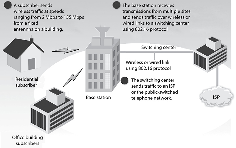
Figure 4-26 Broadband wireless in a MAN
NOTE IEEE 802.16 is a standard for vendors to follow to allow for interoperable broadband wireless connections. IEEE does not test for compliance to this standard. The WiMAX Forum runs a certification program that is intended to guarantee compliance with the standard and interoperability with equipment between vendors.
802.15.4
This standard deals with a much smaller geographical network, which is referred to as a wireless personal area network (WPAN). This technology allows for connectivity to take place among local devices, such as a computer communicating with a wireless keyboard, a cellular phone communicating with a computer, or a headset communicating with another device. The goal here—as with all wireless technologies—is to allow for data transfer without all of those pesky cables. The IEEE 802.15.4 standard operates in the 2.4-GHz band, which is part of what is known as the Industrial, Scientific and Medical (ISM) band and is unlicensed in many parts of the world. This means that vendors are free to develop products in this band and market them worldwide without having to obtain licenses in multiple countries.
Devices that conform to the IEEE 802.15.4 standard are typically low-cost, low-bandwidth, and ubiquitous. They are very common in industrial settings where machines communicate directly with other machines over relatively short distances (typically no more than 100 meters). For this reason, this standard is emerging as a key enabler of the Internet of Things (IoT), in which everything from your thermostat to your door lock is (relatively) smart and connected.
ZigBee is one of the most popular protocols based on the IEEE 802.15.4 standard. It is intended to be simpler and cheaper than most WPAN protocols and is very popular in the embedded device market. ZigBee links are rated for 250 kbps and support 128 bit symmetric key encryption. You can find ZigBee in a variety of home automation, industrial control, medical, and sensor network applications.
Bluetooth Wireless
The Bluetooth wireless technology has a 1- to 3-Mbps transfer rate and works in a range of approximately 1, 10, or 100 meters. If you have a cell phone and a tablet that are both Bluetooth-enabled and both have calendar functionality, you could have them update each other without any need to connect them physically. If you added some information to your cell phone contacts list and task list, for example, you could just place the phone close to your tablet. The tablet would sense that the other device was nearby, and it would then attempt to set up a network connection with it. Once the connection was made, synchronization between the two devices would take place, and the tablet would add the new contacts list and task list data. Bluetooth works in the frequency range of other 802.11 devices (2.4 GHz).
Real security risks exist when transferring unprotected data via Bluetooth in a public area, because any device within a certain range can capture this type of data transfer.
One attack type that Bluetooth is vulnerable to is referred to as Bluejacking. In this attack, someone sends an unsolicited message to a device that is Bluetooth-enabled. Bluejackers look for a receiving device (phone, tablet, laptop) and then send a message to it. Often, the Bluejacker is trying to send someone else their business card, which will be added to the victim’s contact list in their address book. The countermeasure is to put the Bluetooth-enabled device into nondiscoverable mode so others cannot identify this device in the first place. If you receive some type of message this way, just look around you. Bluetooth only works within a 10-meter distance, so it is coming from someone close by.
NOTE Bluesnarfing is the unauthorized access from a wireless device through a Bluetooth connection. This allows access to a calendar, contact list, e-mails, and text messages, and on some phones users can copy pictures and private videos.
Best Practices for Securing WLANs
There is no silver bullet to protect any of our devices or networks. That being said, there are a number of things we can do that will increase the cost of the attack for the adversary. Some of the best practices pertaining to WLAN implementations are as follows:
• Change the default SSID. Each AP comes with a preconfigured default SSID value.
• Implement WPA2 and 802.1X to provide centralized user authentication (e.g., RADIUS, Kerberos). Before users can access the network, require them to authenticate.
• Use separate VLANs for each class of users, just as you would on a wired LAN.
• If you must support unauthenticated users (e.g., visitors), ensure they are connected to an untrusted VLAN that remains outside your network’s perimeter.
• Deploy a wireless intrusion detection system (WIDS).
• Physically put the AP at the center of the building. The AP has a specific zone of coverage it can provide.
• Logically put the AP in a DMZ with a firewall between the DMZ and internal network. Allow the firewall to investigate the traffic before it gets to the wired network.
• Implement VPN for wireless devices to use. This adds another layer of protection for data being transmitted.
• Configure the AP to allow only known MAC addresses into the network. Allow only known devices to authenticate. But remember that these MAC addresses are sent in cleartext, so an attacker could capture them and masquerade himself as an authenticated device.
• Carry out penetration tests on the WLAN. Use the tools described in this section to identify APs and attempt to break the current encryption scheme being used.
Satellites
Today, satellites are used to provide wireless connectivity between different locations. For two different locations to communicate via satellite links, they must be within the satellite’s line of sight and footprint (area covered by the satellite). The sender of information (ground station) modulates the data onto a radio signal that is transmitted to the satellite. A transponder on the satellite receives this signal, amplifies it, and relays it to the receiver. The receiver must have a type of antenna—one of those circular, dish-like things we see on top of buildings. The antenna contains one or more microwave receivers, depending upon how many satellites it is accepting data from.
Satellites provide broadband transmission that is commonly used for television channels and PC Internet access. If a user is receiving TV data, then the transmission is set up as a one-way network. If a user is using this connection for Internet connectivity, then the transmission is set up as a two-way network. The available bandwidth depends upon the antenna and terminal type and the service provided by the service provider. Time-sensitive applications can suffer from the delays experienced as the data goes to and from the satellite. These types of satellites are placed into a low Earth orbit, which means there is not as much distance between the ground stations and the satellites as in other types of satellites. In turn, this means smaller receivers can be used, which makes low-Earth-orbit satellites ideal for two-way paging, international cellular communication, TV stations, and Internet use.
NOTE The two main microwave wireless transmission technologies are satellite (ground to orbiter to ground) and terrestrial (ground to ground).
The size of the footprint depends upon the type of satellite being used. It can be as large as a country or only a few hundred feet in circumference. The footprint covers an area on the Earth for only a few hours or less, so the service provider usually has a large number of satellites dispatched to provide constant coverage at strategic areas.
In most cases, organizations will use a system known as a very small aperture terminal (VSAT), which links a remote office to the Internet through a satellite gateway facility run by a service provider, as shown in Figure 4-27. Alternatively, VSATs can be deployed in stand-alone networks in which the organization also places a VSAT at a central location and has all the remote ones reach into it with no need for a gateway facility. The data rates available can range from a few Kbps to several Mbps. Dropping prices have rendered this technology affordable to many midsized organizations.
Mobile Wireless Communication
Mobile wireless has now exploded into a trillion-dollar industry, with over 7.2 billion subscriptions, fueled by a succession of new technologies and by industry and international standard agreements.
So what is a mobile phone anyway? It is a device that can send voice and data over wireless radio links. It connects to a cellular network, which is connected to the PSTN. So instead of needing a physical cord and connection that connects your phone and the PSTN, you have a device that allows you to indirectly connect to the PSTN as you move around a wide geographic area.
Radio stations use broadcast networks, which provide one-way transmissions. Mobile wireless communication is also a radio technology, but it works within a cellular network that employs two-way transmissions.
A cellular network distributes radio signals over delineated areas, called cells. Each cell has at least one fixed-location transceiver (base station) and is joined to other cells to provide connections over large geographic areas. So as you are talking on your mobile phone and you move out of range of one cell, the base station in the original cell sends your connection information to the next base station so that your call is not dropped and you can continue your conversation.

Figure 4-27 Satellite broadband
We do not have an infinite number of frequencies to work with when it comes to mobile communication. Millions of people around the world are using their cell phones as you read this. How can all of these calls take place if we only have one set of frequencies to use for such activity? A rudimentary depiction of a cellular network is shown in Figure 4-28. Individual cells can use the same frequency range, as long as they are not right next to each other. So the same frequency range can be used in every other cell, which drastically decreased the amount of ranges required to support simultaneous connections.
The industry had to come up with other ways to allow millions of users to be able to use this finite resource (frequency range) in a flexible manner. Over time, mobile wireless has been made up of progressively more complex and more powerful “multiple access” technologies, listed here:
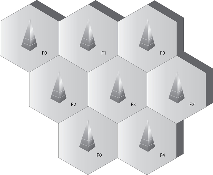
Figure 4-28 Nonadjacent cells can use the same frequency ranges.
• Frequency division multiple access (FDMA)
• Time division multiple access (TDMA)
• Code division multiple access (CDMA)
• Orthogonal frequency division multiple access (OFDMA)
We quickly go over the characteristics of each of these technologies because they are the foundational constructs of the various cellular network generations.
Frequency division multiple access (FDMA) was the earliest multiple access technology put into practice. The available frequency range is divided into sub-bands (channels), and one channel is assigned to each subscriber (cell phone). The subscriber has exclusive use of that channel while the call is made, or until the call is terminated or handed off; no other calls or conversations can be made on that channel during that call. Using FDMA in this way, multiple users can share the frequency range without the risk of interference between the simultaneous calls. FDMA was used in the first generation (1G) of cellular networks. 1G mobile had various implementations, such as Advanced Mobile Phone System (AMPS), Total Access Communication System (TACS), and Nordic Mobile Telephone (NMT), used FDMA.
Time division multiple access (TDMA) increases the speed and efficiency of the cellular network by taking the radio-frequency spectrum channels and dividing them into time slots. At various time periods, multiple users can share the same channel; the systems within the cell swap from one user to another user, in effect, reusing the available frequencies. TDMA increased speeds and service quality. A common example of TDMA in action is a conversation. One person talks for a time and then quits, and then a different person talks. In TDMA systems, time is divided into frames. Each frame is divided into slots. TDMA requires that each slot’s start and end time are known to both the source and the destination. Mobile communication systems such as Global System for Mobile Communication (GSM), Digital AMPS (D-AMPS), and Personal Digital Cellular (PDC) use TDMA.
Code division multiple access (CDMA) was developed after FDMA, and as the term “code” implies, CDMA assigns a unique code to each voice call or data transmission to uniquely identify it from all other transmissions sent over the cellular network. In a CDMA “spread spectrum” network, calls are spread throughout the entire radio-frequency band. CDMA permits every user of the network to simultaneously use every channel in the network. At the same time, a particular cell can simultaneously interact with multiple other cells. These features make CDMA a very powerful technology. It is the main technology for the mobile cellular networks that presently dominate the wireless space.

Orthogonal frequency division multiple access (OFDMA) is derived from a combination of FDMA and TDMA. In earlier implementations of FDMA, the different frequencies for each channel were widely spaced to allow analog hardware to separate the different channels. In OFDMA, each of the channels is subdivided into a set of closely spaced orthogonal frequencies with narrow bandwidths (subchannels). Each of the different subchannels can be transmitted and received simultaneously in a multiple input, multiple output (MIMO) manner. The use of orthogonal frequencies and MIMO allows signal processing techniques to reduce the impacts of any interference between different subchannels and to correct for channel impairments, such as noise and selective frequency fading. 4G requires that OFDMA be used.
Mobile wireless technologies have gone through a whirlwind of confusing generations. The first generation (1G) dealt with analog transmissions of voice-only data over circuit-switched networks. This generation provided a throughput of around 19.2 Kbps. The second generation (2G) allows for digitally encoded voice and data to be transmitted between wireless devices, such as cell phones, and content providers. TDMA, CDMA, GSM, and PCS all fall under the umbrella of 2G mobile telephony. This technology can transmit data over circuit-switched networks and supports data encryption, fax transmissions, and short message services (SMSs).
The third-generation (3G) networks became available around the turn of the century. Incorporating FDMA, TDMA, and CDMA, 3G had the flexibility to support a great variety of applications and services. Further, circuit switching was replaced with packet switching. Modular in design to allow ready expandability, backward compatibility with 2G networks, and stressing interoperability among mobile systems, 3G services greatly expanded the applications available to users, such as global roaming (without changing one’s cell phone or cell phone number), as well as Internet services and multimedia.
In addition, reflecting the ever-growing demand from users for greater speed, latency in 3G networks was much reduced as transmission speeds were enhanced. More enhancements to 3G networks, often referred to as 3.5G or as mobile broadband, are taking place under the rubric of the Third Generation Partnership Project (3GPP). 3GPP has a number of new or enhanced technologies. These include Enhanced Data Rates for GSM Evolution (EDGE), High-Speed Downlink Packet Access (HSDPA), CDMA2000, and Worldwide Interoperability for Microwave Access (WiMAX).
There are two competing technologies that fall under the umbrella of 4G, which are Mobile WiMAX and Long-Term Evolution (LTE). A 4G system does not support traditional circuit-switched telephony service as 3G does, but works over a purely packet-based network. 4G devices are IP-based and are based upon OFDMA instead of the previously used multiple carrier access technologies.
Research projects have started on fifth-generation (5G) mobile communication, but standards requirements and implementation are not expected until 2020.

Table 4-4 The Different Characteristics of Mobile Technology
Each of the different mobile communication generations has taken advantage of the improvement of hardware technology and processing power. The increase in hardware has allowed for more complicated data transmission between users and hence the desire for more users to want to use mobile communications.
Table 4-4 illustrates some of the main features of the 1G through 4G networks. It is important to note that this table does not and cannot easily cover all the aspects of each generation. Earlier generations of mobile communication have considerable variability between countries. The variability was due to country-sponsored efforts before agreed-upon international standards were established. Various efforts between the ITU and countries have attempted to minimize the differences.
NOTE While it would be great if the mobile wireless technology generations broke down into clear-cut definitions, they do not. This is because various parts of the world use different foundational technologies, and there are several competing vendors in the space with their own proprietary approaches.
Networking Foundations
Networking has made amazing advances in just a short period of time. In the beginning of the Computer Age, mainframes were the name of the game. They were isolated powerhouses, and many had “dumb” terminals hanging off them. However, this was not true networking. In the late 1960s and early 1970s, some technical researchers came up with ways of connecting all the mainframes and Unix systems to enable them to communicate. This marked the Internet’s baby steps.
Microcomputers evolved and were used in many offices and work areas. Slowly, dumb terminals got a little smarter and more powerful as users needed to share office resources. And bam! Ethernet was developed, which allowed for true networking. There was no turning back after this.
While access to shared resources was a major drive in the evolution of networking, today the infrastructure that supports these shared resources and the services these components provide is really the secret to the secret sauce. As we will see, networks are made up of routers, switches, web servers, proxies, firewalls, name resolution technologies, protocols, IDS, IPS, storage systems, antimalware software, virtual private networks, demilitarized zones (DMZs), data loss prevention solutions, e-mail systems, cloud computing, web services, authentication services, redundant technologies, public key infrastructure, private branch exchange (PBX), and more. While functionality is critical, there are other important requirements that need to be understood when architecting a network, such as scalability, redundancy, performance, security, manageability, and maintainability.
Infrastructure provides foundational capabilities that support almost every aspect of our lives. When most people think of technology, they focus on the end systems that they interact with—laptops, mobile phones, tablet PCs, workstations, etc.—or the applications they use, such as e-mail, fax, Facebook, websites, instant messaging, Twitter, and online banking. Most people do not even give a thought to how this stuff works under the covers, and many people do not fully realize all the other stuff that is dependent upon technology: medical devices, critical infrastructure, weapon systems, transportation, satellites, telephony, etc. People say it is love that makes the world go around, but let them experience one day without the Internet. We are all more dependent upon the Matrix than we fully realize, and as security professionals we need to not only understand the Matrix, but also secure it.
Network Topology
The arrangement of computers and devices is called a network topology. Topology refers to the manner in which a network is physically connected and shows the layout of resources and systems. A difference exists between the physical network topology and the logical topology. A network can be configured as a physical star but work logically as a ring, as in the Token Ring technology.
The best topology for a particular network depends on such things as how nodes are supposed to interact; which protocols are used; the types of applications that are available; the reliability, expandability, and physical layout of a facility; existing wiring; and the technologies implemented. The wrong topology or combination of topologies can negatively affect the network’s performance, productivity, and growth possibilities.
This section describes the basic types of network topologies. Most networks are much more complex and are usually implemented using a combination of topologies.
Ring Topology
A ring topology has a series of devices connected by unidirectional transmission links, as shown in Figure 4-29. These links form a closed loop and do not connect to a central system, as in a star topology (discussed later). In a physical ring formation, each node is dependent upon the preceding nodes. In simple networks, if one system fails, all other systems could be negatively affected because of this interdependence. Today, most networks have redundancy in place or other mechanisms that will protect a whole network from being affected by just one workstation misbehaving, but one disadvantage of using a ring topology is that this possibility exists.
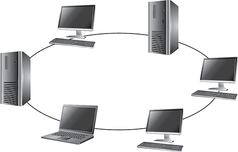
Figure 4-29 A ring topology forms a closed-loop connection.
Bus Topology
In a simple bus topology, a single cable runs the entire length of the network. Nodes are attached to the network through drop points on this cable. Data communications transmit the length of the medium, and each packet transmitted has the capability of being “looked at” by all nodes. Each node decides to accept or ignore the packet, depending upon the packet’s destination address.
Bus topologies are of two main types: linear and tree. The linear bus topology has a single cable with nodes attached. A tree topology has branches from the single cable, and each branch can contain many nodes.
In simple implementations of a bus topology, if one workstation fails, other systems can be negatively affected because of the degree of interdependence. In addition, because all nodes are connected to one main cable, the cable itself becomes a potential single point of failure. Traditionally, Ethernet uses bus and star topologies.
Star Topology
In a star topology, all nodes connect to a central device such as a switch. Each node has a dedicated link to the central device. The central device needs to provide enough throughput that it does not turn out to be a detrimental bottleneck for the network as a whole. Because a central device is required, it is a potential single point of failure, so redundancy may need to be implemented. Switches can be configured in flat or hierarchical implementations so larger organizations can use them.
When one workstation fails on a star topology, it does not affect other systems, as in the ring or bus topologies. In a star topology, each system is not as dependent on others as it is dependent on the central connection device. This topology generally requires less cabling than other types of topologies. As a result, cut cables are less likely, and detecting cable problems is an easier task.
Not many networks use true linear bus and ring topologies anymore. A ring topology can be used for a backbone network, but most networks are constructed in a star topology because it enables the network to be more resilient and not as affected if an individual node experiences a problem.
Mesh Topology
In a mesh topology, all systems and resources are connected to each other in a way that does not follow the uniformity of the previous topologies, as shown in Figure 4-30. This arrangement is usually a network of interconnected routers and switches that provides multiple paths to all the nodes on the network. In a full mesh topology, every node is directly connected to every other node, which provides a great degree of redundancy. A typical IoT home automation network using ZigBee is an example of a full mesh topology. In a partial mesh topology, every node is not directly connected. The Internet is an example of a partial mesh topology.
A summary of the different network topologies and their important characteristics is provided in Table 4-5.
Media Access Technologies
The physical topology of a network is the lower layer, or foundation, of a network. It determines what type of media will be used and how the media will be connected between different systems. Media access technologies deal with how these systems communicate over this media and are usually represented in protocols, NIC drivers, and interfaces. LAN access technologies set up the rules of how computers will communicate on a network, how errors are handled, the maximum transmission unit (MTU) size of frames, and much more. These rules enable all computers and devices to communicate and recover from problems, and enable users to be productive in accomplishing their networking tasks. Each participating entity needs to know how to communicate properly so all other systems will understand the transmissions, instructions, and requests. This is taken care of by the LAN media access technology.

Figure 4-30 In a mesh topology, each node is connected to all other nodes, which provides for redundant paths.

Table 4-5 Summary of Network Topologies
NOTE An MTU is a parameter that indicates how much data a frame can carry on a specific network. Recall that a data frame is the data encapsulation structure that exists at layer 2 (data link) of the OSI model. Different types of network technologies may require different MTU sizes, which is why frames are sometimes fragmented.
These technologies reside at the data link layer of the OSI model. Remember that as a message is passed down through a network stack, it is encapsulated by the protocols and services at each layer. When the data message reaches the data link layer, the protocol at this layer adds the necessary headers and trailers that will allow the message to traverse a specific type of network (Ethernet, Token Ring, FDDI, etc.) The protocol and network driver work at the data link layer, and the NIC works at the physical layer, but they have to work together and be compatible. If you install a new server on an Ethernet network, you must implement an Ethernet NIC and driver.
The LAN-based technologies we will cover in the next sections are Ethernet, Token Ring, and FDDI. We covered wireless networking technologies earlier in the chapter.
A local area network (LAN) is a network that provides shared communication and resources in a relatively small area. What defines a LAN, as compared to a WAN, depends on the physical medium, encapsulation protocols, and media access technology. For example, a LAN could use 10Base-T cabling, TCP/IP protocols, and Ethernet media access technology, and it could enable users who are in the same local building to communicate. A WAN, on the other hand, could use fiber-optic cabling, the L2TP encapsulation protocol, and ATM media access technology and could enable users from one building to communicate with users in another building in another state (or country). A WAN connects LANs over great distances geographically. Most of the differences between these technologies are found at the data link layer.
Token Passing A token is a 24-bit control frame used to control which computers communicate at what intervals. The token is passed from computer to computer, and only the computer that has the token can actually put frames onto the wire. The token grants a computer the right to communicate. The token contains the data to be transmitted and source and destination address information. When a system has data it needs to transmit, it has to wait to receive the token. The computer then connects its message to the token and puts it on the wire. Each computer checks this message to determine whether it is addressed to it, which continues until the destination computer receives the message. The destination computer makes a copy of the message and flips a bit to tell the source computer it did indeed get its message. Once this gets back to the source computer, it removes the frames from the network. The destination computer makes a copy of the message, but only the originator of the message can remove the message from the token and the network.
If a computer that receives the token does not have a message to transmit, it sends the token to the next computer on the network. An empty token has a header, data field, and trailer, but a token that has an actual message has a new header, destination address, source address, and a new trailer.
This type of media-sharing method is used by Token Ring and FDDI technologies.
NOTE Some applications and network protocols work better if they can communicate at determined intervals, instead of “whenever the data arrives.” In token-passing technologies, traffic arrives in this type of deterministic nature because not all systems can communicate at one time; only the system that has control of the token can communicate.
CSMA Ethernet protocols define how nodes are to communicate, recover from errors, and access the shared network cable. Ethernet uses CSMA to provide media-sharing capabilities. There are two distinct types of CSMA: CSMA/CD and CSMA/CA.
A transmission is called a carrier, so if a computer is transmitting frames, it is performing a carrier activity. When computers use the carrier sense multiple access with collision detection (CSMA/CD) protocol, they monitor the transmission activity, or carrier activity, on the wire so they can determine when would be the best time to transmit data. Each node monitors the wire continuously and waits until the wire is free before it transmits its data. As an analogy, consider several people gathered in a group talking here and there about this and that. If a person wants to talk, she usually listens to the current conversation and waits for a break before she proceeds to talk. If she does not wait for the first person to stop talking, she will be speaking at the same time as the other person, and the people around them may not be able to understand fully what each is trying to say.
When using the CSMA/CD access method, computers listen for the absence of a carrier tone on the cable, which indicates that no other system is transmitting data. If two computers sense this absence and transmit data at the same time, a collision can take place. A collision happens when two or more frames collide, which most likely corrupts both frames. If a computer puts frames on the wire and its frames collide with another computer’s frames, it will abort its transmission and alert all other stations that a collision just took place. All stations will execute a random collision timer to force a delay before they attempt to transmit data. This random collision timer is called the back-off algorithm.
NOTE Collisions are usually reduced by dividing a network with routers or switches.
Carrier sense multiple access with collision avoidance (CSMA/CA) is a medium-sharing method in which each computer signals its intent to transmit data before it actually does so. This tells all other computers on the network not to transmit data right now because doing so could cause a collision. Basically, a system listens to the shared medium to determine whether it is busy or free. Once the system identifies that the “coast is clear” and it can put its data on the wire, it sends out a broadcast to all other systems, telling them it is going to transmit information. It is similar to saying, “Everyone shut up. I am going to talk now.” Each system will wait a period of time before attempting to transmit data to ensure collisions do not take place. The wireless LAN technology 802.11 uses CSMA/CA for its media access functionality.
NOTE When there is just one transmission medium (i.e., UTP cable) that has to be shared by all nodes and devices in a network, this is referred to as a contention-based environment. Each system has to “compete” to use the transmission line, which can cause contention.
Collision Domains As indicated in the preceding section, a collision occurs on Ethernet networks when two computers transmit data at the same time. Other computers on the network detect this collision because the overlapping signals of the collision increase the voltage of the signal above a specific threshold. The more devices on a contention-based network, the more likely collisions will occur, which increases network latency (data transmission delays). A collision domain is a group of computers that are contending, or competing, for the same shared communication medium.
An unacceptable amount of collisions can be caused by a highly populated network, a damaged cable or connector, too many repeaters, or cables that exceed the recommended length. If a cable is longer than what is recommended by the Ethernet specification, two computers on opposite ends of the cable may transmit data at the same time. Because the computers are so far away from each other, they may both transmit data and not realize that a collision took place. The systems then go merrily along with their business, unaware that their packets have been corrupted. If the cable is too long, the computers may not listen long enough for evidence of a collision. If the destination computers receive these corrupted frames, they then have to send a request to the source system to retransmit the message, causing even more traffic.
These types of problems are dealt with mainly by implementing collision domains. An Ethernet network has broadcast and collision domains. One subnet will be on the same broadcast and collision domain if it is not separated by routers or bridges. If the same subnet is divided by bridges, the bridges can enable the broadcast traffic to pass between the different parts of a subnet, but not the collisions, as shown in Figure 4-31. This is how collision domains are formed. Isolating collision domains reduces the amount of collisions that take place on a network and increases its overall performance.
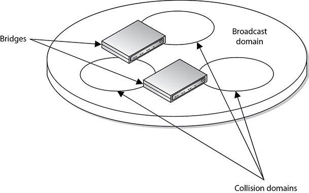
Figure 4-31 Collision domains within one broadcast domain
EXAM TIP Broadcast domains are sets of computing nodes that all receive a layer 2 broadcast frame. These are normally all nodes that are interconnected by switches, hubs, or bridges but with no routers in between them. Collision domains are sets of computing nodes that may produce collisions when they transmit data. These are normally nodes connected by hubs, repeaters, or wireless access points.
Another benefit of restricting and controlling broadcast and collision domains is that it makes sniffing the network and obtaining useful information more difficult for an intruder as he traverses the network. A useful tactic for attackers is to install a Trojan horse that sets up a network sniffer on the compromised computer. The sniffer is usually configured to look for a specific type of information, such as usernames and passwords. If broadcast and collision domains are in effect, the compromised system will have access only to the broadcast and collision traffic within its specific subnet or broadcast domain. The compromised system will not be able to listen to traffic on other broadcast and collision domains, and this can greatly reduce the amount of traffic and information available to an attacker.
Polling The third type of media-sharing method is polling. In an environment where a polling LAN media access and sharing method is used, some systems are configured as primary stations and others are configured as secondary stations. At predefined intervals, the primary station asks the secondary station if it has anything to transmit. This is the only time a secondary station can communicate.
Polling is a method of monitoring multiple devices and controlling network access transmission. If polling is used to monitor devices, the primary device communicates with each secondary device in an interval to check its status. The primary device then logs the response it receives and moves on to the next device. If polling is used for network access, the primary station asks each device if it has something to communicate to another device. Network access transmission polling is used mainly with mainframe environments.
So remember that there are different media access technologies (Ethernet, Token Ring, FDDI, Wi-Fi) that work at the data link and physical layers of the OSI model. These technologies define the data link protocol, NIC and NIC driver specifications, and media interface requirements. These individual media access technologies have their own way of allowing systems to share the one available network transmission medium—Ethernet uses CSMACD, Token Ring uses tokens, FDDI uses tokens, Wi-Fi uses CSMACA, and mainframe media access technology uses polling. The media-sharing technology is a subcomponent of the media access technology.
The term “local” in the context of a LAN refers not so much to the geographical area as to the limitations of a LAN with regard to the shared medium, the number of devices and computers that can be connected to it, the transmission rates, the types of cable that can be used, and the compatible devices. If a network administrator develops a very large LAN that would more appropriately be multiple LANs, too much traffic could result in a big performance hit, or the cabling could be too long, in which case attenuation (signal loss) becomes a factor. Environments where there are too many nodes, routers, and switches may be overwhelmed, and administration of these networks could get complex, which opens the door for errors, collisions, and security holes. The network administrator should follow the specifications of the technology he is using, and once he has maxed out these numbers, he should consider implementing two or more LANs instead of one large LAN. LANs are defined by their physical topologies, data link layer technologies, protocols, and devices used. The following sections cover these topics and how they interrelate.
Ethernet
Ethernet is a set of technologies that enables several devices to communicate on the same network. Ethernet usually uses a bus or star topology. If a linear bus topology is used, all devices connect to one cable. If a star topology is used, each device is connected to a cable that is connected to a centralized device, such as a switch. Ethernet was developed in the 1970s, became commercially available in 1980, and was officially defined through the IEEE 802.3 standard.
Ethernet has seen quite an evolution in its short history, from purely coaxial cable installations that worked at 10 Mbps to mostly Category 5 twisted-pair cable that works at speeds of 100 Mbps, 1,000 Mbps (1 Gbps), and 10 Gbps.
Ethernet is defined by the following characteristics:
• Contention-based technology (all resources use the same shared communication medium)
• Uses broadcast and collision domains
• Uses the carrier sense multiple access with collision detection (CSMA/CD) access method
• Supports full-duplex communication
• Can use coaxial, twisted-pair, or fiber-optic cabling types
• Is defined by standard IEEE 802.3
Ethernet addresses how computers share a common network and how they deal with collisions, data integrity, communication mechanisms, and transmission controls. These are the common characteristics of Ethernet, but Ethernet does vary in the type of cabling schemes and transfer rates it can supply. Several types of Ethernet implementations are available, as outlined in Table 4-6. The following sections discuss 10Base-T, 100BaseTX, 1000Base-T, and 10GBase-T, which are common implementations.
10Base-T 10Base-T uses twisted-pair copper wiring instead of coaxial cabling. Twisted-pair wiring uses one wire to transmit data and the other to receive data. 10Base-T is usually implemented in a star topology, which provides easy network configuration. In a star topology, all systems are connected to centralized devices, which can be in a flat or hierarchical configuration.
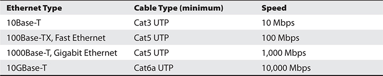
Table 4-6 Ethernet Implementation Types
10Base-T networks have RJ-45 connector faceplates to which the computer connects. The wires usually run behind walls and connect the faceplate to a punchdown block within a wiring closet. The punchdown block is often connected to a 10Base-T hub that serves as a doorway to the network’s backbone cable or to a central switch. This type of configuration is shown in Figure 4-32.

Figure 4-32 Ethernet hosts connect to a punchdown block within the wiring closet, which is connected to the backbone via a hub or switch.
100Base-TX Not surprisingly, 10 Mbps was considered heaven-sent when it first arrived on the networking scene, but soon many users were demanding more speed and power. The smart people had to gather into small rooms and hit the whiteboards with ideas, calculations, and new technologies. The result of these meetings, computations, engineering designs, and testing was Fast Ethernet.
Fast Ethernet is regular Ethernet, except that it runs at 100 Mbps over twisted-pair wiring instead of at 10 Mbps. Around the same time Fast Ethernet arrived, another 100-Mbps technology was developed: 100-VG-AnyLAN. This technology did not use Ethernet’s traditional CSMA/CD and did not catch on like Fast Ethernet did.
Fast Ethernet uses the traditional CSMA/CD (explained in the “CSMA” section later in the chapter) and the original frame format of Ethernet. This is why it is used in many enterprise LAN environments today. One environment can run 10- and 100-Mbps network segments that can communicate via 10/100 hubs or switches.
1000Base-T Improved Ethernet technology has allowed for gigabit speeds over a Category 5 wire. In the 1000Base-T version, all four pairs of twisted unshielded cable pairs are used for simultaneous transmission in both directions for a maximum distance of 100 meters. Negotiation takes place on two pairs, and if two Gigabit Ethernet devices are connected through a cable with only two pairs, the devices will successfully choose “gigabit” as the highest common denominator.
10GBase-T Naturally, the need for faster network protocols continues unabated. After Gigabit Ethernet, the next step was to increase the performance tenfold in order to achieve 10 Gigabit throughputs. In order to do this, engineers had to do away with the venerable CSMA/CD technology that had been at the heart of the 802.3 standards. They also used sophisticated digital signal processing schemes to mitigate the effects of crosstalk and noise, which become increasingly problematic as the data rates increase.
10G Ethernet has not seen the rapid and widespread adoption of Gigabit Ethernet, primarily because of its cost-to-performance ratio. Still, it continues to grow steadily in the enterprise, particularly for interconnecting servers and network storage devices.
We will touch upon Ethernet again later in the chapter because it has beat out many of the other competing media access technologies. While Ethernet started off as just a LAN technology, it has evolved and is commonly used in metropolitan area networks (MANs) also.
Token Ring
Like Ethernet, Token Ring is a LAN media access technology that enables the communication and sharing of networking resources. The Token Ring technology was originally developed by IBM and then defined by the IEEE 802.5 standard. At first, Token Ring technology had the ability to transmit data at 4 Mbps. Later, it was improved to transmit at 16 Mbps. It uses a token-passing technology with a star-configured topology. The ring part of the name pertains to how the signals travel, which is in a logical ring. Each computer is connected to a central hub, called a Multistation Access Unit (MAU). Physically, the topology can be a star, but the signals and transmissions are passed in a logical ring.
A token-passing technology is one in which a device cannot put data on the network wire without having possession of a token, a control frame that travels in a logical circle and is “picked up” when a system needs to communicate. This is different from Ethernet, in which all the devices attempt to communicate at the same time. This is why Ethernet is referred to as a “chatty protocol” and has collisions. Token Ring does not endure collisions, since only one system can communicate at a time, but this also means communication takes place more slowly compared to Ethernet.
Token Ring employs a couple of mechanisms to deal with problems that can occur on this type of network. The active monitor mechanism removes frames that are continuously circulating on the network. This can occur if a computer locks up or is taken offline for one reason or another and cannot properly receive a token destined for it. With the beaconing mechanism, if a computer detects a problem with the network, it sends a beacon frame. This frame generates a failure domain, which is between the computer that issued the beacon and its neighbor downstream. The computers and devices within this failure domain will attempt to reconfigure certain settings to try to work around the detected fault. Figure 4-33 depicts a Token Ring network in a physical star configuration.
Token Ring networks were popular in the 1980s and 1990s, and although some are still around, Ethernet has become much more popular and has taken over the LAN networking market.

Figure 4-33 A Token Ring network
FDDI
Fiber Distributed Data Interface (FDDI) technology, developed by the American National Standards Institute (ANSI), is a high-speed, token-passing, media access technology. FDDI has a data transmission speed of up to 100 Mbps and is usually used as a backbone network using fiber-optic cabling. FDDI also provides fault tolerance by offering a second counter-rotating fiber ring. The primary ring has data traveling clockwise and is used for regular data transmission. The second ring transmits data in a counterclockwise fashion and is invoked only if the primary ring goes down. Sensors watch the primary ring and, if it goes down, invoke a ring wrap so the data will be diverted to the second ring. Each node on the FDDI network has relays that are connected to both rings, so if a break in the ring occurs, the two rings can be joined.
When FDDI is used as a backbone network, it usually connects several different networks, as shown in Figure 4-34.
Before Fast Ethernet and Gigabit Ethernet hit the market, FDDI was used mainly as campus and service provider backbones. Because FDDI can be employed for distances up to 100 kilometers, it was often used in MANs. The benefit of FDDI is that it can work over long distances and at high speeds with minimal interference. It enables several tokens to be present on the ring at the same time, causing more communication to take place simultaneously, and it provides predictable delays that help connected networks and devices know what to expect and when.
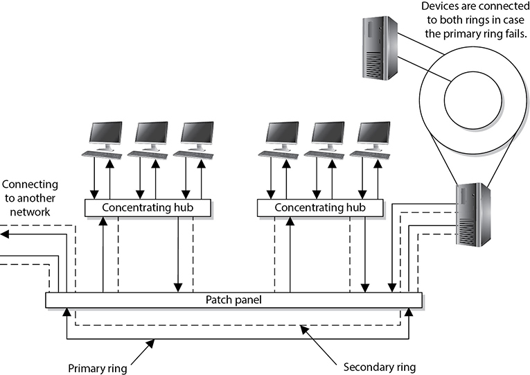
Figure 4-34 FDDI rings can be used as backbones to connect different LANs.
NOTE FDDI-2 provides fixed bandwidth that can be allocated for specific applications. This makes it work more like a broadband connection with QoS capabilities, which allows for voice, video, and data to travel over the same lines.
A version of FDDI, Copper Distributed Data Interface (CDDI), can work over UTP cabling. Whereas FDDI would be used more as a MAN, CDDI can be used within a LAN environment to connect network segments.
Devices that connect to FDDI rings fall into one of the following categories:
• Single-attachment station (SAS) Attaches to only one ring (the primary) through a concentrator
• Dual-attachment station (DAS) Has two ports and each port provides a connection for both the primary and the secondary rings
• Single-attached concentrator (SAC) Concentrator that connects an SAS device to the primary ring
• Dual-attached concentrator (DAC) Concentrator that connects DAS, SAS, and SAC devices to both rings
The different FDDI device types are illustrated in Figure 4-35.
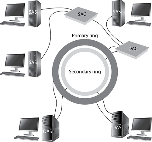
Figure 4-35 FDDI device types
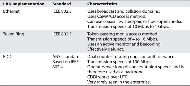
Table 4-7 LAN Media Access Methods
NOTE Ring topologies are considered deterministic, meaning that the rate of the traffic flow can be predicted. Since traffic can only flow if a token is in place, the maximum time that a node will have to wait to receive traffic can be determined. This can be beneficial for time-sensitive applications.
Table 4-7 sums up the important characteristics of the technologies described in the preceding sections.