
Chapter 3
Wireless LAN Infrastructure Devices
The following CWTS exam objectives are covered in this chapter:
- 2.1: Identify the purpose, features, and functions of the following wireless network components. Choose the appropriate installation or configuration steps in a given scenario.
- Access Points
- Controller-based
- Autonomous
- Cooperative
- Mesh
- Wireless LAN Routers
- Wireless Bridges
- Wireless Repeaters
- WLAN Controllers
- Distributed and centralized data forwarding
- Power over Ethernet (PoE) Devices
- 802.3af and 802.3at
- Midspan
- Endpoint
- Access Points
Choosing the correct wireless LAN infrastructure devices to be installed as part of a computer network is a critical element of a successful wireless LAN deployment. In this chapter, we will look at a variety of infrastructure devices, including wireless access points, wireless mesh devices, wireless bridges, wireless repeaters, and wireless LAN controllers. This chapter will describe some of the features, benefits, and advantages of these and other infrastructure devices. Power over Ethernet (PoE) is an extension to the IEEE 802.3 Ethernet standard that allows direct current voltage to be supplied over Ethernet cable to any PoE-capable device. Power over Ethernet now consists of two ratified amendments and is commonly used in enterprise wireless LAN deployments. This chapter will discuss the concepts involved in PoE, including both of its amendments to the IEEE 802.3 standard.
The Wireless Access Point
The wireless access point (AP) is an integral component of a wireless LAN infrastructure. Wireless access points are what allow a variety of wireless devices access to any network resources that the device or user may have permissions for. Wireless access points are available in three common types—autonomous, controller-based, and cooperative. Autonomous access points are self-contained units and can function as independent network infrastructure devices. Controller-based access points, by contrast, function in conjunction with the wireless LAN controller. Cooperative access points provide a wireless infrastructure without the use of a hardware controller. This chapter discusses all three types of access points—autonomous, controller-based, and cooperative. The AP provides computers, voice over Wi-Fi phones, tablets, and other wireless devices access to a local area network using radio frequency (RF) as the communication mechanism through free space (air) as the communication medium.
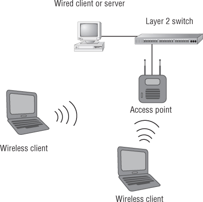
When a wireless device is connected to an access point, it is said to be in infrastructure mode. In this operation mode, all wireless data traffic is passed through the access point to the intended destination, whether that is a file server, a printer, the Internet, or anything else. An access point can operate as a standalone network device, in which it is configured independently to allow wireless devices to connect. It can also operate as part of a larger wireless network by sharing some of the same configurations, such as the service set identifier (SSID). The SSID is the logical name or identifier that all devices connected to the access point will share. Figure 3.1 shows an example of an access point connected to an Ethernet network.
Figure 3.1 Access point connected to an Ethernet network
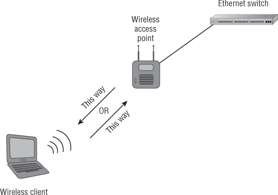
In addition to providing access through a shared medium, access points are half-duplex devices. Half duplex in computer terminology is defined as two-way communication that occurs in only one direction at a time. (By contrast, full duplex, the other communication method used in computer networking, allows two-way communication to occur between devices simultaneously.) Communication only one way at a time means less data throughput for the connected device. An access point is a network infrastructure device that can connect to a distribution system (DS)—typically an Ethernet segment or Ethernet cable—and allow wireless users to access network resources. According to the IEEE 802.11 standards, access points are considered stations (abbreviated STA). In a completely Ethernet-switched network, devices will communicate directly with the Ethernet switch. Figure 3.2 illustrates half-duplex communication in a wireless network.

Autonomous Access Points
Autonomous access points are self-contained units with all the intelligence necessary to provide devices with wireless access to a wired network infrastructure and access to the resources the devices have permission to use. There are two popular types of autonomous access points—small-office home-office (SOHO) and enterprise. Not surprisingly, the enterprise type offers generally more robust features.
Figure 3.2 Half duplex—communication one direction at a time
The SOHO Access Point
Although they are very powerful devices, SOHO-grade access points usually have a less extensive feature set than enterprise-grade access points. However, most consumer (SOHO)-grade and enterprise-grade access points now support the highest standards-based security options available, including Wi-Fi Protected Access 2.0 (WPA 2.0) certifications. SOHO or consumer-grade access points are best used in the SOHO or home environment and usually have a limited number of connections for computers and devices. SOHO-grade access points have the following features:
- IEEE 802.11 standards support
- Wi-Fi Alliance certifications
- Removable antennas
- Static output transmit power
- Advanced security options
- Wireless bridge functionality
- Wireless repeater functionality
- Dynamic Host Configuration Protocol (DHCP) server
- Configuration and settings options
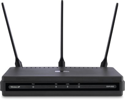
Figure 3.3 shows an example of a SOHO access point.
Figure 3.3 DLink DAP-2553 AirPremier N dual-band PoE SOHO access point
IEEE 802.11 Standards Support
Most later-model SOHO access points support the current IEEE 802.11 standards, whereas others require firmware updates for standards compliance. Some older devices have no firmware update available, which can cause implementation challenges where interoperability between newer and legacy devices is required. The 802.11 standards supported will vary based on several factors, including the cost and complexity of the unit. The most common SOHO access points support the IEEE 802.11b, IEEE 802.11g, and IEEE 802.11n communication amendments. Dual-band access points (which support both IEEE 802.11a/n and IEEE 802.11b/g/n) are not as common in the SOHO market. Most equipment manufacturers do make dual-band models, but the cost is normally higher than single-band (IEEE 802.11b/g/n) consumer-grade access points. The wireless residential wireless gateway or broadband router is another popular device in the SOHO environment. We will learn more about wireless residential gateways later in this chapter. See Chapter 2, “Introduction to Wireless Local Area Networking,” if you need to review these 802.11 amendments.
Wi-Fi Alliance Certifications
Certifications from the Wi-Fi Alliance are a common feature of SOHO access points. As mentioned in Chapter 2, these certifications include WPA/WPA 2.0 and WPS for security, and WMM and WMM-PS for QoS. Selecting a SOHO access point that is Wi-Fi certified ensures compliance with IEEE standards and interoperability with other devices.
Removable Antennas
Some SOHO access points are equipped with removable antennas. This allows the end user to change to a larger (higher-gain) antenna, thereby allowing a radio frequency to cover a wider area. Conversely, connecting a smaller (lower-gain) antenna will decrease the coverage area. Antennas and radio frequency radiation patterns are discussed in Chapter 7, “WLAN Antennas and Accessories.” Many SOHO access points have fixed or nonremovable antennas, so you cannot add a higher-gain antenna.
![]()
Static Output Transmit Power
Occasionally an end user will have the ability to adjust the transmit output power in a SOHO access point. If this is available, the settings are usually very basic, such as low, medium, and high. With enterprise access points you can change the power in increments of mW or dBm. The transmit output power will determine in part the area of radio frequency coverage, also known as the cell. The typical transmit output power of a SOHO model access point is about 15 dBm or 32 mW; however, this will vary with the manufacturer. An access point model with static output power cannot be adjusted, which will limit your ability to decrease or increase the size of the radio frequency cell. Changing the cell size will allow the user to cover a larger area in the home or small office where the access point is installed. In this case, the only way to change the cell size is to change the gain of the antenna in models that have the removable antenna feature. Note that replacing the antenna will also change the vertical and horizontal beamwidths or radiation pattern that propagates away from it.
Advanced Security Options
All newer-model SOHO access points support the highest security features, including IEEE 802.11i, and WPA 2.0 personal and enterprise modes. These security features give users with limited technical knowledge the ability to provide the most up-to-date security for their wireless network. For those users who have greater technical know-how, SOHO access points also provide more advanced security features, such as 802.1X/EAP or virtual private network (VPN) pass-through. Users can find more information about these advanced features in most user guides provided with the access point or online at the manufacturers' website.
Wireless Bridge Functionality
SOHO access points occasionally can be configured in wireless bridge mode. Both point-to-point and point-to-multipoint settings are available, enabling administrators to connect two or more wired LANs together wirelessly.
Wireless Repeater Functionality
Some SOHO access points can be configured to function as wireless repeaters. Configuring an access point as a repeater enables administrators to extend the size of the radio frequency cell, so that devices not in hearing range of an access point can connect to the wireless network. However, the cost is reduced throughput for other devices accessing the network through a wireless repeater.
Dynamic Host Configuration Protocol (DHCP) Server
It's also common for SOHO access points to be able to act as Dynamic Host Configuration Protocol (DHCP) servers. A DHCP server will automatically issue an Internet Protocol (IP) address (logical address) to allow upper-layer communication between devices on the network. IP addresses are a function of Layer 3 of the OSI model, as outlined in Chapter 1, “Introduction to Computer Networking.”
Configuration and Settings Options
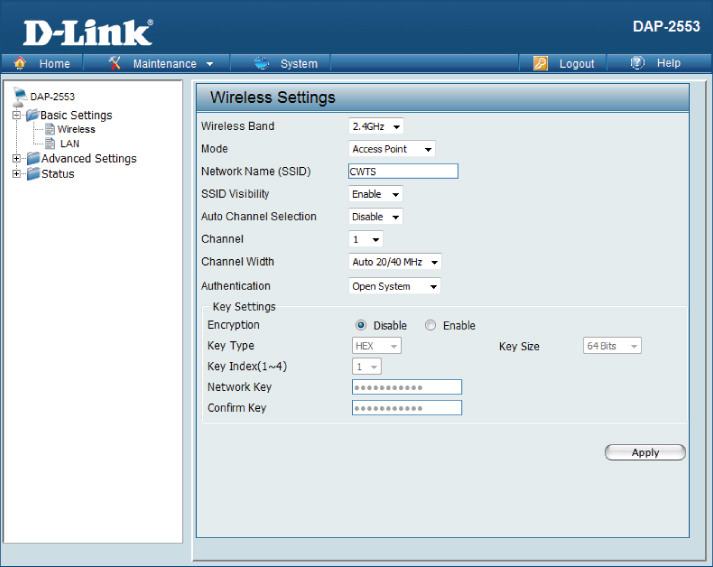
SOHO access points are configured via a web browser, using either HTTP (Hypertext Transfer Protocol) or HTTPS (Hypertext Transfer Protocol Secure). This type of browser-based configuration is an easy way for the novice administrator to make all the necessary settings based on the application in which the access point will be used. SOHO access points rarely offer configuration from the command line interface (CLI). Figure 3.4 shows a sample of a configuration page from a SOHO access point.
Figure 3.4 SOHO access point configuration page in a web browser
For security, however, it is best practice to configure the access point from the wired side of the network whenever possible. Configuration should only be done wirelessly if absolutely necessary. If configuring the access point from the wireless side is the only option, a secure connection should be in place to prevent unauthorized access.
The Enterprise Access Point
Enterprise access points typically have a much more extensive feature set than the previously mentioned SOHO access points. This section will look at some of the more advanced features available in enterprise-grade access points.
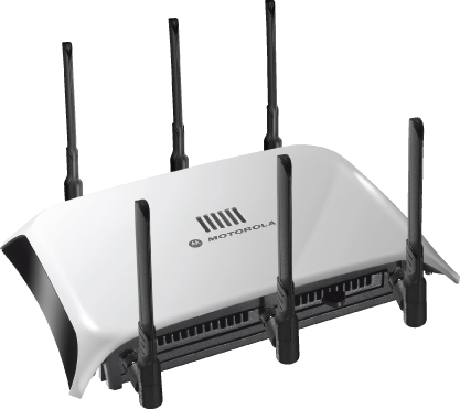
Figure 3.5 shows an enterprise-grade access point.
Figure 3.5 The Motorola AP 7131 IEEE 802.11n dual-band access point
Enterprise-grade access points can include the following features:
- IEEE 802.11 standards support
- Wi-Fi Alliance certifications
- Removable or expandable antennas
- Adjustable output transmit power
- Advanced security options
- Multiple operation modes, including root access point, wireless bridge, and wireless repeater capabilities
- Graphical user interface (GUI) configuration
- Command-line interface configuration
In addition to the items listed here, enterprise-grade access points have various other features that make them stand above the SOHO-grade access point. Some of these features include outdoor use, plenum ratings, industrial environment ratings, more memory, and faster processors to help handle the load and various environmental conditions.
IEEE 802.11 Standards Support
Like SOHO access points, enterprise access points also support IEEE standards. Enterprise access points have a more extensive feature set than SOHO access points, and depending on the manufacturer and model, they will support all communication standards by utilizing IEEE 802.11a/n and IEEE 802.11b/g/n dual-band radios. Enterprise-grade access points can include support for some amendments to the standard not supported by SOHO-grade access points. Examples include support for IEEE 802.11e QoS, Wi-Fi multimedia, IEEE 802.11r fast BSS transition (FT), and IEEE 802.11w for the security of management frames, to name a few.
Wi-Fi Alliance Certifications
Certifications by the Wi-Fi Alliance are an important feature of enterprise-grade access points. These certifications include WPA/WPA 2.0 for Security, WMM, and WMM-PS for QoS. Selecting an enterprise-grade access point that is Wi-Fi certified ensures compliance with IEEE standards and interoperability with other IEEE 802.11-compliant devices.
Removable or Expandable Antennas
Many enterprise access points have removable or expandable antenna capabilities. These antenna configurations provide a lot of flexibility, as an installer can choose the appropriate antenna based on the deployment scenario. Omnidirectional, semidirectional, and highly directional antennas are all types of antennas commonly used in the enterprise environment. Enterprise-quality access points that use internal antennas can offer options for connecting external antennas should they be required. Antennas will be discussed in more detail in Chapter 7.
Adjustable Output Transmit Power
Unlike some SOHO-grade access points, enterprise-grade access points have the capability to adjust output transmit power. This feature allows an installer to select the correct amount of transmit power based on the installation needs of the access point. One benefit of having adjustable output power is that an installer can adapt to the environment in which the access point is installed. If the radio frequency dynamics of an area change, the ability to change access point settings, such as output transmit power, without physical intervention is beneficial.
Advanced Security Options
Compared to access points used in the SOHO environment, enterprise access points typically have more advanced security features. In addition to IEEE 802.11i, WPA/WPA 2.0, passphrase, and IEEE 802.1X, features such as a built-in user database for local Remote Authentication Dial-In User Service (RADIUS) authentication are also included. As discussed later in this chapter, local RADIUS authentication allows small to medium-sized businesses to provide their own advanced authentication features without the need of external RADIUS authentication services. This reduces costs and lowers administration overhead.
RADIUS is just one example of the more advanced security features available in enterprise-level access points. Another advanced security feature that may be available is some level of a wireless intrusion prevention system (WIPS). A WIPS will help determine and have the potential to mitigate certain levels of wireless intrusions or attacks on the network. One example is the detection of a rogue (unknown) access point. Advanced security features are discussed in more detail in Chapter 9, “Wireless LAN Security Basics.”
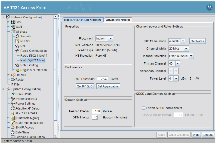
Some other configuration options available for one model of enterprise access point are shown in Figure 3.6.
Figure 3.6 Motorola AP-7131 Enterprise-grade access point configuration page in a web browser
Multiple Operation Modes
In addition to the features we've just discussed, enterprise access points typically have several operation modes. These modes are:
Access point configuration methods
Controller-Based Access Points
Controller-based access points differ from autonomous access points in that they are used with wireless LAN controllers and not as standalone devices. (As discussed in the previous section, an autonomous access point is a self-contained unit that has all the intelligence needed to provide computer and device access to a wireless network.) Controller-based access points have shifted much of the intelligence to the wireless LAN controller. Since a controller-based access point contains less intelligence than an autonomous access point, the cost of a controller-based access point can be significantly lower.
Controller-based access points are centrally managed from the wireless LAN controller. Depending on the manufacturer, they may have a more extensive feature set than autonomous access points, while also including many of the features of those devices. One of these features is Layer 3 VPN connectivity for computers and other devices. Figure 3.7 shows a typical controller-based access point.
Figure 3.7 Aruba Dual-Radio 802.11a/n + 802.11b/g/n using three antennas

Cooperative Access Points
Cooperative access point technology provides an alternative for deploying wireless local area network infrastructures. Cooperative networks are sometimes referred to as a “controllerless architecture,” because the intelligence has been pushed back out to or distributed to the access point edge, similar to that of the autonomous access point but with much more intelligence and capabilities. The access points are managed through a “cloud” software configuration tool, eliminating the need for a hardware controller. This software control can be accessed from any computer with an Internet connection, assuming the user has appropriate permissions. Some manufacturers also have “software appliances,” eliminating the reliance on the cloud server. Many if not all of the benefits, features, and advantages available with the wireless LAN controller architecture are also available in the cooperative or controllerless architecture and are explained later in this chapter. Figure 3.8 shows an example of cooperative access points.
Cooperative access points provide all the benefits and features of a wireless LAN controller solution without the need and extra expense of a hardware controller. This technology is scalable and performs well without relying on a “tunnel” to be built from the access point to a controller. This distributed intelligence allows the cooperative access point to make decisions about how frames traverse both the wired and wireless network.
Some manufacturers of controller-based solutions provide a variant of the cooperative technology by allowing autonomous access points to be “adoptable” by a controller in a large enterprise environment. These access points are then site survivable, meaning they will still be able to function standalone should connectivity with the controller be temporarily lost. The description of this technology includes the term “adaptive access point.”
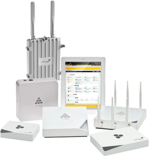
Figure 3.8 The Aerohive family of cooperative-control access points
Wireless Mesh
Wireless mesh networking continues to grow at a steady pace. The concept of mesh networking has been in existence for many years. In a full mesh network, all nodes connect together with at least two paths for every node. This allows for reliable communication in the event of a device or path failure.
Wireless mesh networking is popular in the outdoor market. Some examples where wireless mesh networks are currently utilized are:
- Metropolitan
- University campuses
- Public safety
- Transportation
- Government
- Amphitheaters
Most outdoor mesh infrastructure devices provide the highest levels of wireless security and are usually inside a rugged weatherproof enclosure for protection from the elements.
Currently many wireless LAN manufacturers use proprietary mechanisms and protocols for wireless mesh networking. IEEE 802.11s is an amendment to the IEEE 802.11 standard to include wireless mesh networking that was ratified in 2011. Many enterprise-grade access points have the ability to operate in mesh mode, whereas others have a dedicated mesh function.
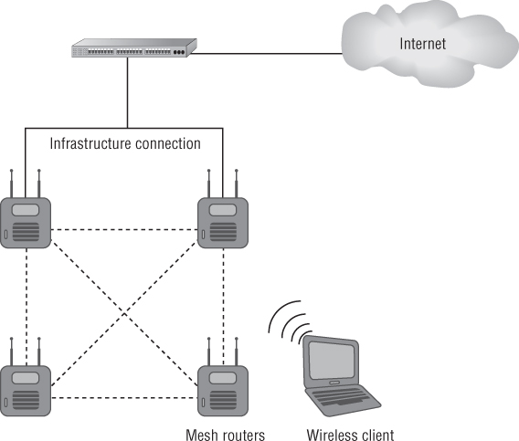
Wireless mesh networking for indoor deployments is still in the testing phase. Some manufacturers recommend using both unlicensed bands for mesh operation. One common solution is to use the 2.4 GHz ISM band for device access and the 5 GHz UNII band for mesh device connectivity. The use of a third radio may be an option in some cases. Mesh can also be used in the event of Ethernet loss to an access point. Some cooperative access points are able to automatically mesh together when they suffer an Ethernet loss. They typically by default support clients in both bands but can mesh in 5 GHz if an Ethernet connection fails. Figure 3.9 illustrates mesh access points connected to a wired infrastructure.
Figure 3.9 Mesh access points/routers connected to a common infrastructure and to the Internet
Wireless LAN Routers
Wireless LAN routers can be defined differently depending on the application. In the SOHO or home market, a wireless LAN router is also known as a wireless broadband router. The CWNP program and associated material refer to these devices as wireless residential gateways. In the enterprise environment, a wireless LAN router has similar functionality plus extended features and is known as a wireless VPN router.
Wireless Residential Gateway
SOHO or home broadband routers (also known as wireless residential gateways) are usually equipped with an Internet port, several ports for Ethernet switches, and a wireless access point. These routers are configured through a web browser using either the HTTP or HTTPS protocols. Configuration of the devices is fairly simple for the novice user using a web browser via a built-in web server. In most cases, a broadband wireless router connects to either a cable modem or a digital subscriber line (DSL) connection available from an Internet service provider (ISP). In this configuration, a router is able to accept wired and wireless connections for computers and other devices, providing them access to the LAN or the Internet. Some of the features of a broadband router include:
- Network Address Translation (NAT)
- Dynamic Host Configuration Protocol (DHCP) server
- IP routing
- Domain Name System (DNS) services
- Firewall
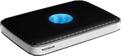
A wireless broadband router has many of the same features as a SOHO access point. An example of a wireless broadband router is shown in Figure 3.10.
Figure 3.10 Netgear WNDR3300 RangeMax dual-band wireless-N router
Wireless Branch Router
A wireless branch router can be used to extend a corporate network to a remote location such as a home, conference room, or branch office through a secure connection using a WAN or the Internet. This type of device typically has three interfaces available:
- Ethernet port(s) to connect to a LAN
- Internet port to connect to the WAN or to an Internet connection
- Wireless port to allow IEEE 802.11 computers and devices to connect to a network through a wireless connection
Wireless branch routers are usually compact and lightweight, making them easy for sales representatives and other corporate employees to travel with. They also have a more extensive feature set than wireless broadband routers, including Layer 3 VPN tunnels between devices and the router on each side that acts as a VPN endpoint or pass-through. Other features include:
- Point-to-Point Tunneling Protocol (PPTP)
- Layer 2 Tunneling Protocol/Internet Protocol Security (L2TP/IPSec)
- SSH2
- Advanced IP networking services
- Edge router capability
Figure 3.11 shows an example of a wireless branch router.
Figure 3.11 Aerohive BR200 wireless branch router
Wireless Bridges
Wireless bridges connect two or more wired LANs together. As discussed in Chapter 2, typically there are two configurations for wireless bridges: point-to-point or point-to-multipoint. A wireless bridge is a dedicated device that functions in much the same way as an access point in bridge mode. Wireless bridges have many of the same features as enterprise access points, including removable antennas and selectable power levels.
Connecting locations together using wireless bridging has many benefits, including fast installation, cost savings, and high data transfer rates. Depending on the circumstances, a wireless bridge can be installed in as little as one day. Cost savings can be enormous compared to installing and maintaining a physical wired connection between locations, whether it is copper, fiber optics, or a leased line from a service provider.
Wireless bridges can work in either the 2.4 GHz ISM or 5 GHz UNII band. The connection can span long distances, so it is important to take security and environmental conditions into consideration as well as the proper antenna selection.
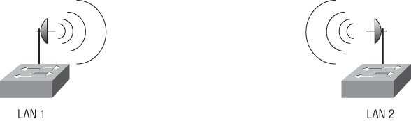
Figure 3.12 illustrates wireless bridges connecting two LANs.
Figure 3.12 Wireless bridges connecting two LANs
Wireless Repeaters
Wireless repeaters are used to extend the radio frequency cell. In a wired Ethernet network, repeaters function at Layer 1 of the OSI model to extend the Ethernet segment. An Ethernet repeater lacks intelligence—that is, it cannot determine data traffic types and simply passes all data traffic across the device. Since wireless infrastructure devices including repeaters are Layer 2 devices, they have more intelligence than Ethernet repeaters.
Just as an Ethernet segment has a maximum distance for successful data transmission, wireless LANs do as well. This distance depends on several factors, including the transmit power of the access point and the gain of the antenna. Like an access point, the wireless client device is also a transmitter and a receiver and will have a radio frequency range limited by the transmit power and gain of the antenna. A wireless repeater provides the capability for computers and other devices to connect to a wireless LAN even when outside the normal hearing range of the access point connected to the network. Figure 3.13 illustrates how a wireless repeater can extend the range of a wireless network.
Figure 3.13 A wireless repeater extends the range of a wireless network.
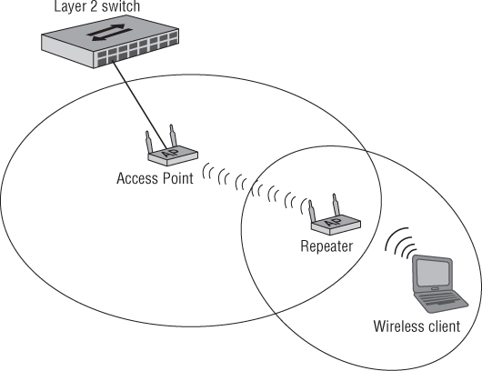
As illustrated, the wireless client is not within hearing range of the access point, so adequate communication is not possible between these devices. In order for wireless LAN devices to communicate effectively with an access point, the transmitter must be able to hear the receiver, and the receiver must be able to hear the transmitter. A wireless repeater will allow this communication to occur in the case where the wireless client is outside the radio frequency cell or basic service area (BSA) of the access point. The wireless client will send information or frames to the repeater and the repeater will forward them to the access point, and vice versa. The downside of this configuration is that it will reduce the overall throughput as described. The wireless repeater may be named differently by the manufacturer and include the term wireless range extender.
![]()
Wireless LAN Controllers
Wireless LAN controllers are a main component in many wireless LAN deployments. Wireless LAN controllers range from branch office models with a few controller-based access points to large-scale enterprise devices with hundreds or even thousands of controller-based access points. The branch office models are typically used in remote office installations or small/medium business (SMB) applications with a limited number of access points. This section discusses some of the many benefits, features, and advantages available on wireless LAN controllers:
- Centralized administration
- Controller-based access points
- Virtual LAN (VLAN)
- Power over Ethernet (PoE) capability
- Improved device roaming
- Wireless profiles
- Advanced security features
- Captive portal
- Built-in RADIUS services
- Site survey tools
- Radio frequency spectrum management
- Firewall
- Quality of service
- Redundancy
- Wireless intrusion prevention system (WIPS)
- Direct or distributed AP connectivity
- Layer 2 and Layer 3 AP connectivity
Centralized Administration
A wireless LAN controller with centralized administration gives an administrator complete control over the wireless network from a single location. Unlike autonomous access points that require intervention at each device for configuration, a wireless LAN controller can be a “one-stop shop” for configuration and management of the wireless network. A wireless network management system (WNMS) can be used as a centralized tool to manage autonomous access points. A WNMS be used to help scale the autonomous access point architecture but is not required.
Controller-Based Access Points
The benefits of controller-based access points are similar to those of autonomous access points, including radio frequency management, security, and quality of service. But controller-based access points can cost less than autonomous access points, and very little or no information is contained within the devices. Controller-based access points are PoE-capable for ease of deployment in either mid-sized or large organizations.
Virtual LAN
According to the IEEE 802.1Q standard, virtual local area networks (VLANs) define broadcast domains in a Layer 2 network by inserting VLAN membership information into Ethernet frames. Layer 2 Ethernet switches can create broadcast domains based on how the switch is configured by using VLAN technology. This allows an administrator to separate physical ports into logical networks to organize traffic according to the use of the VLAN for security profiles, QoS, or other applications. The concept of a Layer 2 wired VLAN is extended to IEEE 802.11 wireless LANs. Wireless LAN controllers have the ability to configure broadcast domains and segregate broadcast and multicast traffic between VLANs.
Power over Ethernet Capability
Wireless LAN controllers support Power over Ethernet (PoE), allowing direct current voltage and computer data to be sent over the same cable. Details of PoE are discussed later in this chapter in the section “Power over Ethernet.”
Improved Device Roaming
Fast seamless Layer 2 and Layer 3 roaming between access points is another common feature of wireless LAN controllers. This feature is beneficial in order for computers and other wireless devices connected to the wireless LAN to maintain a connection while physically moving throughout the wireless network. As you learned in Chapter 2, the IEEE 802.11r amendment specifies fast transition (FT) and the IEEE 802.11k helps with this functionality. Roaming is more often than not an enterprise requirement and exists in very few SOHO deployments.
Wireless Profiles
A wireless LAN controller can give network administrators the ability to create a variety of configuration profiles. These profiles can work in conjunction with VLANs to allow or deny access based on requirements for the computer, device, or user access. Profiles can be configured for various situations, including different SSIDs for guest, corporate, and voice networks, security configurations, and QoS support. This can also be accomplished with a WNMS for controllerless or cooperative deployments.
Advanced Security Features
Like autonomous access points, wireless LAN controllers will also provide advanced security options. Wireless LAN controllers will include security options based on IEEE 802.11i and WPA/WPA 2.0, with both passphrase and enterprise configuration capabilities.
Captive Portal
Captive portal capability is a common feature in wireless LAN controllers and cooperative-based systems. A captive portal will intercept a user's attempt to access the network by redirecting them to a web page for authorization. This web page may request account credentials, payment information from a user, or a simple agreement to terms and conditions before granting access to the wireless network. One common example where you will see a captive portal is in a paid or free wireless hotspot. The captive portal can be hosted by an outside service provider, an autonomous access point, or a wireless controller, and in a cooperative system on the access point.
Built-in RADIUS Services
Another common feature of wireless LAN controllers and cooperative-based systems is RADIUS services for 802.1X/EAP authentication, which is supported by WPA and WPA 2.0. Built-in RADIUS allows a network administrator to utilize the most advanced security features available today to secure the wireless network. Built-in RADIUS server databases typically have a limited number of users that can be created in the user database, which means that built-in RADIUS is a good solution for SMB or remote office locations but not for very large organizations. Larger networks can use external RADIUS services for scalability. See www.gnu.org/software/radius for more about this server.
Site Survey Tools
Predictive site survey tools assist in placement of access points and other infrastructure devices. These tools are sometimes a feature of a wireless LAN controller. Performing a predictive site survey will assist in planning to determine coverage and capacity for data and voice for both indoor and outdoor deployments.
Aerohive provides a free online wireless network planning tool with an auto-placement feature. See www.aerohive.com/planner for more information and to access this free tool.
Radio Frequency Spectrum Management
Keeping an eye on the radio frequency (RF) environment is another responsibility of the wireless network administrator. RF spectrum management consists of adjusting RF parameters such as the channel (frequency) and the RF transmit power after deployment. This allows the network to adapt to changes in the environment and assist in the event of hardware failures.
Firewall
An integrated stateful firewall feature helps protect a network from unauthorized Internet traffic but still allows authorized traffic. Firewalls can be hardware based, software based, or a combination of the two. Stateful firewalls, which keep records of all connections passing through the firewall, help protect against broadcast storms, rogue DHCP server attacks, Address Resolution Protocol (ARP) poisoning, and other potential attacks against the wireless LAN.
Quality of Service
Quality of service features help time-critical applications such as voice and video communications minimize latency and allow for traffic prioritization. With the continual expansion of voice and video technology in the wireless LAN arena, QoS is becoming an increasingly important component in the wireless network.
Redundancy
Redundancy allows for fault-tolerant deployments and provides uninterrupted access in the event an access point or wireless LAN controller fails. Complete redundancy will prevent a major outage caused by hardware failure for mission-critical or other deployments. Coverage is maintained by alternating access points between the redundant devices, minimizing interruption for user access in the event of a hardware failure.
Wireless Intrusion Prevention System
A wireless intrusion prevention system (WIPS) monitors all activity across the wireless network for potential intrusion and malicious activities. A WIPS can take appropriate action to mitigate an attack based on the type of intrusion.
Direct and Distributed AP Connectivity
Connecting access points that are not directly plugged into a port on the wireless LAN controller is a feature known as distributed AP connectivity and is beneficial in large-scale deployments. Most manufacturers support distributed AP connectivity. Direct AP connectivity is defined as a direct connection to ports on the switch. A typical device with distributed connectivity is shown in Figure 3.14.
Figure 3.14 Meru MC 5000 large-scale enterprise wireless LAN controller

Layer 2 and Layer 3 AP Connectivity
Early wireless network implementations were built with dedicated Layer 2 connectivity, which meant limited wireless mobility. Layer 2 roaming occurs when a computer or other wireless device moves out of the radio cell of the currently connected access point and connects to a different AP maintaining Layer 2 connectivity.
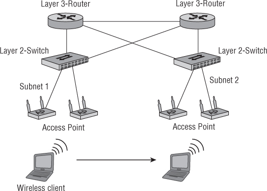
As wireless networking technology evolved, so did the need for Layer 3 connectivity and roaming. IP addresses are logical Layer 3 addresses that identify devices on a network. All IP devices on the same network or subnet are considered to be in the same IP boundary. Layer 3 roaming occurs when a client moves to an AP that covers a different IP subnet. After roaming, the client will no longer have a valid IP address from the original subnet and the device will be issued an IP address from the new subnet while maintaining Layer 3 connectivity. Figure 3.15 illustrates Layer 2 and Layer 3 connectivity.
Figure 3.15 Wireless client device roaming across Layer 2 and Layer 3 boundaries
Distributed and Centralized Data Forwarding
Wireless LAN controller solutions consist of two common types of architectures: centralized and distributed. Early WLAN controller solutions supported the centralized architecture, which is also known as split-MAC architecture. This design separated the intelligence from the access point and placed it into the wireless controller to allow for centralized management and control of the wireless network. The access point for the most part was just a radio and antenna, and traffic decisions were sent to the controller through an Ethernet cable. This technique is also known as centralized data forwarding. Depending on where the controller was placed, it could cause bottlenecks and other issues in the case of an overloaded or poorly designed network infrastructure. With the data rates possible with IEEE 802.11n, the aggregate throughput could be too much for the network to handle, resulting in poor performance.
Distributed data forwarding reduces the amount of infrastructure traffic because the controller-based access point is able to make more decisions, taking some of the load away from the wireless controller. Moving some of the intelligence back to the edge (the wireless access point) minimizes the bottlenecks and other potential issues such as latency. This is also true in a cooperative or controllerless architecture, thus eliminating the need for the data to be sent to the controller for handling. Many wireless LAN equipment manufacturers now support both the centralized and distributed WLAN architectures.
Power over Ethernet
Power over Ethernet (PoE) sends direct current (DC) voltage and computer data over the same Ethernet cable, enabling a device to receive DC power and computer data simultaneously. This eliminates the need for an external alternating current (AC) power source to be near the Ethernet device. Power over Ethernet now consists of two ratified amendments to the IEEE 802.3 standard. It is defined in 802.3-2005 Clause 33, also known as IEEE 802.3af, and IEEE 802.3at, sometimes called PoE+. These amendments define the specifications for devices used in wired or wireless networking to receive DC power from the Ethernet connection without the need for an external DC power source.
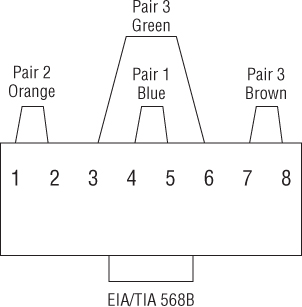
An Ethernet cable has four copper wire pairs or eight copper wires. Depending on the technology in use, either two or all four wired pairs may be used to carry data traffic. Figure 3.16 shows an example of a standard Ethernet cable pin assignment.
The PoE amendments to the Ethernet standard allow electrical power to be supplied in one of two ways, either over the same wired pairs that carry computer data or over the pairs that do not carry data. 10BASE-T and 100BASE-T (Fast Ethernet) implementations use only two wired pairs (four wires) to carry data. 1000BASE-T (Gigabit Ethernet) may use all four pairs (eight wires) to carry computer data. The standard defines which wire pairs are allowed to carry the DC power based on whether the network is 10BASE-T, 100BASE-T, or 1000BASE-T and whether the power is sourced from an endpoint or midspan injector. Both midspan and endpoint are explained later in this chapter.
Figure 3.16 Standard Ethernet pin assignment
The nominal voltage for PoE is 48 VDC, but the amendments allow for a range of 44 to 57 VDC at the power source. The PoE amendments address two types of devices: power sourcing equipment (PSE), the source of the DC power, and the powered device (PD), the receiver of the DC power.
![]()
The IEEE 802.3-2005 Clause 33 (802.3af) amendment was released in 2003 and allocates 15.4 watts (W) of power per port maximum. This amendment has been incorporated into the IEEE 802.3-2008 standard. The IEEE 802.3at amendment, also known as PoE+, was released in 2009 and includes changes to add to the capabilities of the IEEE 802.3-2008 standard with higher power levels and improved power management information. IEEE 802.3at allows for 25.5 W of power per port maximum, a 60 percent increase over IEEE 802.3af. IEEE 802.3af PoE will work with access points from all manufacturers of enterprise-grade IEEE 802.11n access points. Using IEEE 802.3af will make it easier for organizations to transition from older model access points to the newer 802.11n technology, which will improve their client service and provide overall better performance without having to immediately upgrade their PoE infrastructure to IEEE 802.3at.
Power Sourcing Equipment
The power sourcing equipment (PSE) is the device that supplies the DC voltage to the end devices that receive the DC power. The DC voltage (power) can be delivered to the device in one of two ways:
- An endpoint device (usually a wireless LAN controller or an Ethernet switch) delivers DC power directly over the same wire pairs that carry data or over the unused wire pairs.
- A midspan device (usually a single port or multiple port injector) injects DC power into the Ethernet cable over the unused wire pairs or over the data pairs, depending on the version of the standard.
Powered Device
The powered device (PD) is defined as the device receiving DC power, such as a wireless access point, wireless bridge, IP camera, IP phone, and so on. The IEEE 802.3 standard defines the maximum cable length of an Ethernet cable to be 328’ or 100 m. Because of line loss, the standard specifies less maximum power than what is available at the port. Table 3.1 shows the maximum power allowed for both the PSE and the PD.
Table 3.1 Maximum power supplied by PSE and drawn by PD for both amendments to the IEEE 802.3 Ethernet Standard
| Specification | 802.3-2005 clause 33 | 802.3at |
| PSE power maximum | 15.4 W | 25.5 W |
| PD power maximum | 12.95 W | 24.0 W |
Powered Device Classifications
Equipment manufacturers have the option of defining a classification signature. This classification signature determines the maximum amount of power a device requires, thereby allowing the PSE to better manage the amount of power delivered to a specific port. The PoE standard makes five classes of powered device available (class 0 through class 4). Table 3.2 shows the available classes and the amount power in watts for each class for IEEE 802.3-2005 clause 33 (802.3af) devices.
Table 3.2 Classes of powered device described in the PoE amendment to the Ethernet standard, 802.3-2005 clause 33 (802.3af)

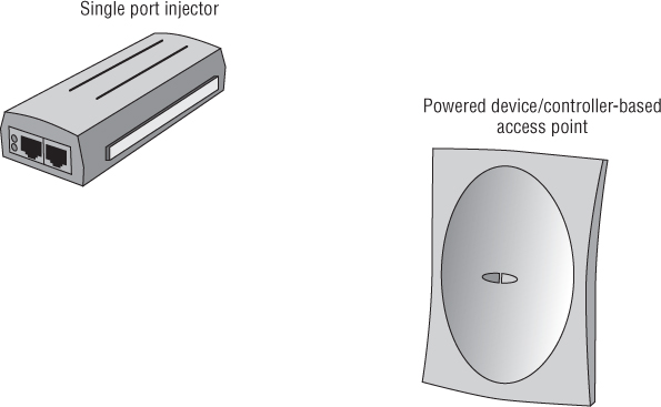
Figure 3.17 shows an example of PSE and a PD.
Figure 3.17 Motorola PSE single-port injector and PD Motorola access port
Benefits of PoE
There are many benefits to using devices that support PoE, including cost savings and convenience. As mentioned in the previous section, the IEEE 802.3 Standard (Ethernet) specifies a maximum distance of 100 m or 328’ for unshielded twisted pair (UTP) Category 5 (CAT5) Ethernet cable. Power over Ethernet enables a PoE device to receive DC power and computer data at this distance without the need for electrical power at the point where the device is installed or located. This can amount to a large cost savings if a voltage source is not available where the device is located, because there is no need to install electrical power at that point.
Midspan Devices
Midspan devices inject the required DC voltage (48V nominal) into the Ethernet cable allowing the AP, bridge, or other powered device to receive electrical power and computer data. There are two types of midspan device—single-port injectors and multiport injectors. A single-port injector supplies power to a single device. This is useful in an implementation that may have only a few PoE devices. A single-port injector is an in-line device that adds DC power to the Ethernet cable. A multiport injector can supply DC power to many devices simultaneously. A multiport injector is an in-line device that functions like a patch panel. Two ports on this device are required to supply both DC power and computer data to a single powered device such as an access point, bridge, or IP camera. Therefore, a 24-port injector will allow connectivity for only 12 devices.
Endpoint Devices
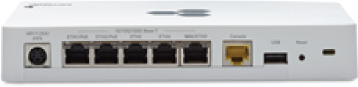
Endpoint devices supply DC power and computer data directly at the Ethernet port rather than relying on an intermediate device to supply the power. Wireless LAN controllers and Ethernet switches are examples of endpoint devices. A benefit of endpoint PoE is that no intermediate adapter to inject power is necessary. Figure 3.18 shows an example of an endpoint PoE device.
Figure 3.18 Cisco wireless controller with PoE endpoint capability
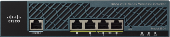
Courtesy of Cisco Systems, Inc. Unauthorized use not permitted.
Summary
This chapter discussed wireless LAN infrastructure devices, which are commonly used to provide wireless connectivity to a network for computers and other wireless devices. These devices include the access point—an integral part of the wireless LAN—available as a self-contained intelligent (autonomous) device, a controller-based device for use with wireless LAN controllers, or a cooperative AP providing user access to network resources. Other infrastructure devices include wireless LAN routers for SOHO or home use, wireless bridges for connecting LANs together, and wireless repeaters for extending the RF cell. This chapter explained some of the features, benefits, and applications of these infrastructure devices. Finally, the chapter covered the two Power over Ethernet (PoE) amendments (IEEE 802.3-2005 Clause 33, also referred to as 802.3af and IEEE 802.3at), components, the DC voltage and amount of DC power supplied (in watts), and how the power may be delivered to an end device.
Exam Essentials
Review Questions
1. In computer network terminology, the definition of half duplex is closest to which of the following?
A. One-way communication only
B. One-way communication one way at a time
C. Two-way communication both directions simultaneously
D. Two-way communication one way at a time
2. A self-contained intelligent access point is:
A. Controller-based
B. Heavyweight
C. Autonomous
D. Thin
3. SOHO access points commonly support which of the following features? (Choose 3.)
A. WPA 2.0 support
B. CLI configuration
C. Static output power
D. Wi-Fi certifications
4. Wireless bridges must be configured with __________and __________. (Choose 2.)
A. A null SSID
B. The same SSID
C. The same RF channel
D. Channel scanning
E. Wired Equivalent Privacy
5. Which of the following is a benefit of a wireless repeater? (Choose 2.)
A. Higher data transfer rate
B. Larger cell size allows more devices to access the medium.
C. Smaller cell size allows fewer devices to access the medium.
D. Less data throughput
E. Extends cell size
6. True or false: A benefit of a wireless LAN controller is distributed administration.
A. True
B. False
7. Static output transmit power of a SOHO access point is typically:
A. 32 dBm
B. 15 dBm
C. 23 mW
D. 15 mW
8. The 802.3-2005 Clause 33 standard specifies __________ VDC as the nominal voltage.
A. 32
B. 57
C. 48
D. 12
9. Which of the following devices is an in-line device that will inject DC voltage into the Ethernet cable?
A. Midspan
B. Midpoint
C. Endspan
D. Endpoint
10. Which layer of the OSI model is responsible for delivering data to a unique hardware address?
A. Layer 1
B. Layer 2
C. Layer 3
D. Layer 4
E. Layer 5
F. Layer 6
G. Layer 7
11. SOHO access points are typically configured by using __________ and __________. (Choose 2.)
A. HTTP
B. FTP
C. HTTPS
D. CLI
E. SMTP
12. True or false: An administrator should always configure an access point from the wireless network.
A. True
B. False
13. Access points work at which layers of the OSI model? (Choose 2.)
A. Layer 1
B. Layer 2
C. Layer 3
D. Layer 4
E. Layer 5
F. Layer 6
G. Layer 7
14. Enterprise access points may contain which of the following features? (Choose 3.)
A. WPA 2.0 support
B. RADIUS server
C. Static output power
D. Repeater mode
E. Power sourcing equipment
15. Which of the following statements is true regarding a wireless LAN controller?
A. Virtual local area networks (VLANs) involve physical separation of ports.
B. Virtual local area networks (VLANs) involve a logical separation of ports.
C. Virtual local area network (VLAN) is another name for a repeater.
D. Virtual local area networks (VLANs) require Power over Ethernet (PoE).
16. A controller-based access point connected to a port on the wireless LAN controller and not to an intermediate device is considered to have which of the following?
A. Direct connectivity
B. Distributed connectivity
C. Decentralized connectivity
D. Centralized connectivity
17. Power sourcing equipment delivers which of the following?
A. RF power to the access point
B. DC power to the end device
C. RF power to an antenna
D. DC power to an antenna
18. Which access point mode involves connecting the access point to a distribution system for user access to the LAN?
A. Bridge only mode
B. Repeater only mode
C. Root access point mode
D. Access mode
19. Which of the following are midspan PoE devices? (Choose 2.)
A. Single-port injectors
B. Multiport injectors
C. Endpoint injectors
D. Endspan injectors
20. Wireless LAN controllers may contain which of the following features? (Choose 3)
A. Centralized administration
B. Captive portal
C. Network Address Translation (NAT)
D. Built-in RADIUS services
E. IP routing