
Chapter 8
Wireless LAN Terminology and Technology
The following CWTS exam objectives are covered in this chapter:
- 1.2 Define basic characteristics of and concepts relating to Wi-Fi technology
- Network discovery via active and passive scanning
- Power saving operation
- Data rates and throughput
- Dynamic rate switching
- 802.11 authentication and association
- The distribution system and roaming
- Infrastructure and ad hoc modes
- BSSID, SSID, BSS, ESS, BSA, IBSS
- Protection mechanisms
This chapter will look at some of the terminology used in IEEE 802.11 wireless networking. 802.11 wireless LANs may be configured in one of two modes: ad hoc or infrastructure mode. We will discuss both of these modes, as well as how the technology is applied and its advantages and disadvantages. In addition, we will examine some of the technical aspects, such as naming the wireless LAN and identifying the devices through Layer 2 MAC addressing or logical names. You will also learn about the methodologies a wireless LAN device or client station uses to locate and connect to the wireless network (these include passive and active scanning as well as the authentication and association processes.
It is important to know how IEEE 802.11 wireless LAN infrastructure devices such as access points are connected using a common wired or wireless distribution system. This distribution system allows access points to communicate with each other and gives the associated and connected wireless LAN devices the capability to roam or move between access points and maintain consistent connectivity across the wireless LAN.
Other wireless LAN technology factors are important to understand when studying IEEE 802.11 wireless networking. This chapter will discuss the differences between data rates and throughput. A sales or technical support specialist should be able to understand and explain why, for example, an IEEE 802.11n access point advertises a maximum data rate of up to 600 Mbps but in many cases the data transfers are half or less than half of this advertised data transfer rate.
Finally, we will look at IEEE 802.11 protection mechanisms in depth and explain why they are needed for backward compatibility and the effect they may have on the data transfer rate.
Some of the topics we will see in this chapter have been briefly touched on in earlier chapters. One of the objectives of this chapter is to tie the terminology and topics together. In wireless LAN technology education, it can be somewhat challenging to cover certain parts of the technology without touching lightly on some other topics. This chapter will tie some of the loose ends together and help you to better understand how IEEE 802.11 wireless networks operate.
Wireless LAN Modes of Operation
Wireless LANs can be configured to operate in different modes for device and user access. Two common modes for access are ad hoc mode and infrastructure mode. These two modes can be broken down into three different configurations:
- Independent basic service set (IBSS)
- Basic service set (BSS)
- Extended service set (ESS)
Each of these configurations will be discussed in more detail in this chapter. The application/deployment scenario for a wireless LAN is the determining factor for the best mode to use. The IBSS configuration does not require the use of an access point and unless specifically justified is not commonly used in enterprise wireless LAN deployments. In addition, if not properly implemented the IBSS can introduce security vulnerabilities, such as potentially bridging the wired network infrastructure to an unsecured wireless network. The most common configuration for an IEEE 802.11 wireless LAN is infrastructure mode, which uses at least one access point. Infrastructure mode requires a minimum of one access point but can consist of up to thousands of access points. The access points are connected by a common medium known as the distribution system. We will look at each of these modes and the details of how they are configured.
The Independent Basic Service Set
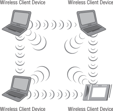
It is important to understand what the independent basic service set (IBSS) is, how it works, and potential uses, advantages, and disadvantages. This wireless LAN operation mode uses no access points and consists of only wireless devices or client computers. Communication occurs only among devices that are part of the same IBSS. Unlike an access point, this mode has no centralized control or manageable security or accounting features. Figure 8.1 shows devices in an IBSS.
Figure 8.1 Example of an independent basic service set (IBSS)
Certain parameters must be set on the devices that wish to participate in an IBSS. These parameters must be the same on all the devices in order for them to effectively communicate with one another. Three common parameters set on devices that belong to the same IBSS are:
- Service set identifier (SSID)
- Radio frequency channel
- Security configuration
The Service Set Identifier
The service set identifier (SSID) is a common parameter used in all wireless LAN operation configurations. Although it is discussed here, it also pertains to the other configurations discussed later in this chapter, such as the basic service set (BSS) and extended service set (ESS). The SSID is the logical name of the service set used to identify the wireless network. The SSID is used by devices to select a wireless network to join. This is accomplished through processes that are known collectively as the discovery phase and include passive and active scanning, both of which will be discussed later in this chapter.
In some cases, naming a wireless network can be a tough decision. Organizations that deploy a wireless network may already have a naming convention in place for such scenarios. If not, a decision will need to be made regarding the wireless network names (SSIDs) used for access points and other devices to identify the wireless LAN.
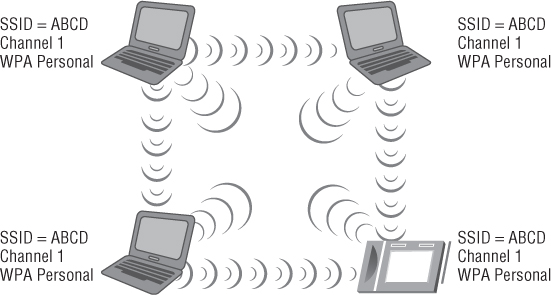
Every device that wishes to be part of the same wireless LAN IBSS, BSS, or ESS will use a common network name, the SSID. (See Figure 8.2 for an IBSS example.) For infrastructure devices such as access points, the SSID parameter is manually set on the access point. From the client access side, the SSID is a user-configurable parameter that can be set manually in the wireless client software utility or received automatically from networks that broadcast this information element.
Figure 8.2 IBSS, ad hoc, or peer-to-peer network using common configuration parameters
The SSID name should be unique and should not divulge who you are or the location of the wireless LAN devices, unless you are trying to create a wireless hotspot or a public accessible IEEE 802.11 wireless network. For example, if a fictitious bank by the name of ABC Bank used an SSID that included ABC_Bank, it would tell an intruder where the wireless network is and could be a potential security threat because a financial institution is a target. It is important to understand if the proper wireless LAN security is enabled, the SSID name should not be an issue, but there is no point in broadcasting certain types of information. Rather than using the bank name in the SSID, consider a unique name that does not describe the business or location.
The SSID is case sensitive and has a maximum limit of 32 characters or, as specified in the IEEE 802.11 standard, 32 octets.
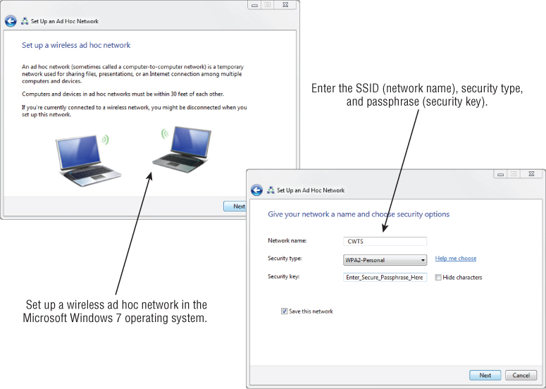
Figure 8.3 shows an example of entering the SSID in the Microsoft Windows 7 AutoConfig wireless configuration client utility for an ad hoc network. First you select “Set up a wireless ad hoc (computer-to-computer) network” in the Set Up A Connection Or Network dialog box; then you enter the SSID on the “Give your network a name and choose security options” Properties page.
The Radio Frequency Channel
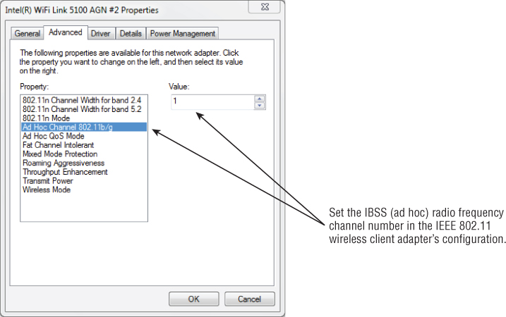
The IBSS wireless network configuration requires a user to set the specific radio frequency channel that will be used by all devices that are part of the same IBSS network. This is accomplished in the client utility software for the network adapter. Some client software utilities set this automatically, in which case the IBSS will use the channel automatically specified. You may also be able to specify the RF channel in the advanced properties of the wireless network adapter device driver properties.
It is important to understand that all wireless devices in any common IBSS must be communicating on the same radio frequency channel. If the client utility does allow a channel to be set, the channel chosen is up to the user but based on the local regulatory domain in which the network is used. Additional devices wishing to join the IBSS must do so by scanning, either passively or by use of active scanning. Figure 8.4 shows an example of setting the RF channel on a notebook computer.
Figure 8.3 Entering the SSID and other parameters in the Microsoft Windows 7 wireless configuration client utility
IBSS Security
With IBSS networks, there is no centralized control and no security management features. Security is left up to the individual user or wireless device. If a user inadvertently shares a resource, it could expose sensitive information and pose security threats. This can be a concern for many enterprise installations, and therefore the use of an IBSS is against corporate security policy in many organizations.
IBSS Terminology
The wireless LAN industry uses several different terms to identify an IBSS. The term used is up to the manufacturer or a specific implementation. An IBSS is usually identified by one of three terms:
- Independent basic service set (IBSS)
- Ad hoc
- Peer-to-peer
Figure 8.4 Setting the RF channel for an IBSS, ad hoc wireless network in the Intel 5100 IEEE 802.11a/g/n wireless network adapter driver Advanced settings page
Regardless of the terminology used—IBSS, ad hoc, or peer-to-peer—it comes down to wireless LAN devices connecting to each other without the use of an access point or other wireless infrastructure device. All devices in an IBSS network work independently of one another, and there is no centralized management or administration capability. This type of connection may be useful in homes or small offices for ease of installation but is rarely if at all used with enterprise or corporate wireless networks.
Advantages and Disadvantages of an IBSS
The advantages and disadvantages of an IBSS network will vary depending on the application.
Some of the advantages of IBSS are as follows:
![]()
![]()
The Basic Service Set
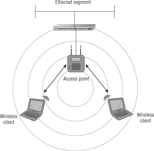
The basic service set (BSS) is the foundation of the wireless network. This mode consists of an access point connected to a network infrastructure and its associated wireless devices. This is considered the foundation because it may be one of many access points that form a wireless network. With a BSS setup, each access point is connected to a network infrastructure, also known as the distribution system (DS), which allows connected wireless LAN devices to access network resources based on the appropriate permissions the wireless device or user has access to. The radio frequency area of coverage depends on several factors, such as the antenna gain and RF output power settings; this area of coverage is known as the basic service area (BSA). Any IEEE 802.11 wireless device in radio range and part of the BSA with the correct configuration parameters, including the SSID and security settings, will be able to successfully connect to the access point. Figure 8.5 shows an example of a BSS.
Figure 8.5 Basic service set consisting of a single access point connected to a distribution system and associated devices
As mentioned earlier, infrastructure mode consists of a wireless access point connected to a distribution system. The BSS consisting of one access point is a common implementation in many homes, SOHO, or small to medium businesses (SMBs). The decision to use a single access point depends on several factors, among them the size of the location, how the wireless network is used, and how many wireless devices will be connected.
Just as in an IBSS configuration, several parameters need to be configured for a BSS. These include the SSID or name of the network, the radio frequency channel to be used, and any security parameters that are set on the BSS. The access point will broadcast these and other parameters about the wireless network to devices that want to connect to the BSS, thus requiring minimal configuration on the wireless client side. Unlike the independent basic service set, in a BSS the radio frequency channel is set on the access point and not on the wireless client device.
Advantages and Disadvantages of a BSS
A BSS has many benefits, advantages, and disadvantages. Some of the advantages are as follows:
- Uses intelligent devices with a large feature set to provide users with consistent, reliable, and secure communications to a wireless network.
- Useful in a variety of situations: homes, SOHO, and small to large businesses.
- Very scalable; you can increase the coverage and capacity of a BSS by adding more access points.
- Centralized administration and control.
- Security parameters and specific access can be set centrally.
Some of the disadvantages of a BSS are as follows:
- Incurs additional hardware costs compared to IBSS.
- Usually will require a site survey to determine radio frequency coverage and capacity requirements.
- Must be connected to a network infrastructure known as the distribution system, either wired or wireless.
- Additional knowledge required for configuration and deployment.
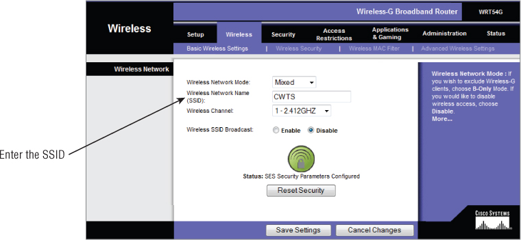
Figure 8.6 shows configuring the SSID on an access point.
Figure 8.6 Graphical user interface for a Cisco Linksys access point configuring the SSID
The Extended Service Set
As stated in the IEEE 802.11-2012 standard, an extended service set (ESS) is defined as a “set of one or more interconnected basic service sets (BSSs) that appears as a single BSS to the logical link control (LLC) layer at any station (STA) associated with one of those BSSs.” In basic terms, this can be one or more access points connected to a common wired or wireless distribution system. An ESS is a common configuration in most wireless LAN deployments for small to medium businesses as well as large enterprise organizations.
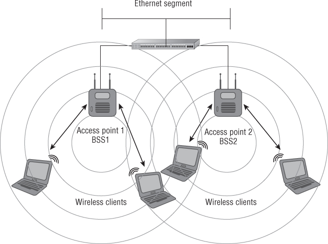
In most cases, an ESS would be used to provide consistent and complete coverage across an entire organization. An ESS can be thought of as several basic service sets (BSSs) that must have matching parameters, such as SSID and security settings. If the SSIDs of two access points do not match, then they are considered separate basic service sets, even though they are connected by a common network infrastructure. It is the distribution system connecting these together and a common network name (SSID) that makes up the ESS. In most cases, the basic service area for each BSS will overlap to allow roaming (transition) from one BSS to another. Figure 8.7 shows an example of an extended service set (ESS).
Figure 8.7 Two basic service sets connected by a common distribution system, making an extended service set
Roaming between access points is a critical component of wireless LAN technology in most modern wireless network deployments. This is because the wireless LAN is now a major part of every corporate network. Many envision a complete wireless network for all communications, including data, voice, and video. Roaming is so important that the IEEE added the 802.11r amendment to provide a standardized methodology for client station roaming and fast secure transition within the wireless LAN.
The Basic Service Area
The basic service area (BSA) is the area of radio frequency coverage or the RF cell that encompasses a wireless access point and its associated stations. A wireless client device will be contained in the basic service area as long as it has enough required receive signal strength to maintain an association state with the wireless access point.
SSID (Service Set Identifier)
ESSID (Extended Service Set Identifier)
BSSID (Basic Service Set Identifier)
Connecting to an IEEE 802.11 Wireless Network
In order for a device to successfully connect to a wireless network, several different frame exchanges must take place. Various frame types allow for specific functions to occur. They include the authentication and association process, reserving the medium, exchanging data, and power save functions. The following section introduces some of the frame types and the roles they play in wireless networking.
IEEE 802.11 Frame Types
As discussed in Chapter 6, “Radio Frequency Fundamentals for Wireless LAN Technology,” devices communicate by sending radio frequency waves to each other through the air. These RF waves carry the digital data from one device to another. At this stage, the information traveling through the air is organized into what are known as frames. These frame types play various roles depending on the information being sent. Wireless LANs use three different frame types.
Management Frames
Management frames are used to manage the network. Management frames assist wireless LAN devices in finding and connecting to a wireless network. This includes advertising the capabilities of the WLAN and allowing connections by the authentication and association process. Management frames are exchanged only between immediate wireless devices such as an access point and client device and never cross the Data Link layer (Layer 2) of the OSI model. It is important to understand that management frames are always transmitted at the lowest mandatory data rate of the service set so that all stations on the same radio frequency channel in the basic service area can understand them. The following are examples of management frames:
- Beacon
- Probe request
- Probe response
- Authentication
- Association request
- Association response
Control Frames
Control frames are used to control access to the wireless medium by allowing devices to reserve the medium and acknowledge data. In addition, some control frames are used to request data from the access point after returning from a power save state and with IEEE 802.11 protection mechanisms to allow wireless device coexistence. Some examples of control frames are as follows:
- RTS
- CTS
- CTS to Self
- PS-Poll
- ACK
Data Frames
As their name implies, data frames are used to carry data payload or Layer 3 information between wireless devices.
A special type of data frame is the null data or null function frame, which helps implement power save features and is not used to carry any data payload. There is also a variant of the null frame called the QoS null frame, which is used with quality of service functions. Examples of data frames include:
- Data
- QoS data
- Null data
The details of the specific functions of each of these frame types are beyond the scope of this book and the CWTS exam objectives, but some of these frames needed to be briefly introduced in order to explain upcoming topics. These include a wireless device “listening” for a network to join, supplying the appropriate credentials, and finally connecting to send data to the network infrastructure.
Wireless Network Discovery
Wireless network discovery is the process of a client device looking for wireless networks and identifying the parameters of the network, including the SSID, supported data rates, and security settings. The discovery phase consists of the passive scanning and active scanning processes. Wireless network discovery prepares a wireless client device to perform an IEEE 802.11 authenticat ion and association, which will allow a device access to the wireless network.
Passive Scanning
The first part of the discovery phase in IEEE 802.11 wireless networking is known as passive scanning. This process allows wireless LAN devices to “listen” for information about wireless networks in the radio receiving area of the wireless network or the basic service area (BSA). During the passive scanning process, wireless LAN devices will listen for specific information to make them aware of networks in the area. An analogy to this process would be using an FM radio tuner to scan through the entire band listening for a station to tune in to. The radio will scan through the band listening for different stations. Once a desired station is heard, the person listening can stop on that specific radio station.
As mentioned earlier in this chapter, management frames assist wireless LAN devices in finding and connecting to a wireless network. An example of a management frame that works in the discovery phase or passive scanning is a beacon frame. This frame for the most part is an advertisement of the wireless network. It carries specific information about the access point or basic service set such as the SSID, the radio frequency channel that it is operating on, the available data rates it is configured for, the security parameters, and much more. During the passive scanning phase, wireless devices listen for beacons advertising the details about the wireless networks in the area or radio range of the client device. Wireless LAN devices are constantly listening for beacon frames. Figure 8.8 shows a wireless LAN client passively scanning and listening for an access point to connect with.
By default, beacons broadcast at about 10 times a second. This value is actually 1024 microseconds and is identified as the target beacon transmission time (TBTT). Although this interval can be changed, it is recommended to do so only if necessary or recommended by the manufacturer. In some cases, manufacturers may suggest specific timing intervals for such frames as beacons.
Figure 8.8 An example of passive scanning with a wireless LAN client listening for access points in the basic service area
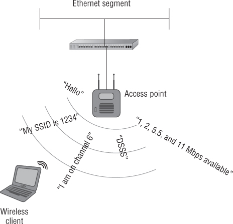
Figure 8.9 shows a packet analyzer capturing beacon frames generated from an access point.
Figure 8.9 Packet analyzer capture of beacon frames

Active Scanning
Active scanning is the second part of the wireless LAN discovery phase. In active scanning, wireless LAN devices wishing to connect to a network send out a management frame known as a probe request. The function of this management frame is to find a specific wireless access point to connect with. Depending on the wireless client utility software used, if an SSID is specified in the client utility software active profile, the device will join only a network with the matching SSID that is specified. An exception to this is a probe request that contains a “wildcard SSID” or a “null SSID.” The IEEE 802.11 standard requires all access points to respond to a “null” or broadcast probe request. This type of probe request frame will not specify an SSID value and will rely on the access points to provide the SSID in the probe response frame. The probe request and probe response frames are discussed in more detail later in this chapter.
Access points constantly listen for probe request frames. Any access point within hearing range of the wireless device and having a matching SSID sends out a probe response frame to the wireless device. If more than one access point responds, the device selects the “best” access point to connect with based on certain factors such as signal strength and signal quality. Figure 8.10 illustrates the active scanning process.
Figure 8.10 Wireless client device sending a probe request frame to access points in radio range
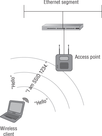
Figure 8.11 shows a packet analyzer capturing frames of the active scanning process.
Figure 8.11 Packet analyzer capture of probe request and probe response frames

IEEE 802.11 Authentication
Authentication in general is defined as verifying or confirming an identity. We use a variety of authentication mechanisms in our daily lives, such as logging onto a computer or network at home or at the office, accessing secure sites on the Internet, using an ATM machine, or showing an identification badge to get access to a building.
IEEE 802.11 devices must use an authentication process in order to access network resources. This IEEE 802.11 authentication process differs from conventional authentication methods such as providing credentials, a username and password to gain access to a network. The authentication discussed here is wireless device or IEEE 802.11 authentication, required in order for the device to become part of the wireless network and participate in exchanging data frames. (Providing credentials such as a username and password or a preshared key is a different type of authentication, to be discussed in Chapter 9.) The IEEE 802.11 standard addresses two types of IEEE authentication methods: open system and shared key.
IEEE 802.11 Open System Authentication
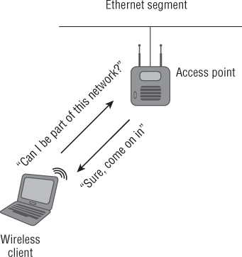
This 802.11 authentication method is defined by the IEEE 802.11 standard as a null authentication algorithm and is a two-step authentication process. Two management frames are exchanged between the device and the access point during open systems authentication. For the most part, open system authentication cannot fail unless other security measures such as MAC filtering are put in place that will prevent the device from accessing the network. Keep in mind that IEEE 802.11 open system authentication always exists, even with the most secure wireless LANs. It is used to allow the wireless station to connect to the access point and then after association use additional credentials such as a passphrase or username and password pair for authentication. If the wireless station did not perform an open system authentication and association first, there would be no way to use additional security mechanisms. IEEE 802.11 open system authentication is the only valid authentication process allowed with newer wireless LAN security amendments and interoperability certifications for the network to be considered a robust security network (RSN).
Open system authentication is a very simple process. A wireless LAN device will ask an access point, “Can I be a part of this network?” and the access point will respond, “Sure, come join the party.” So there really is no validation of identity. Open system authentication is considered a two-way frame exchange because two authentication frames are sent during this process. It is not a request and response situation; it is authentication and success.
Figure 8.12 illustrates open system authentication.
Figure 8.12 A wireless client authenticating to an access point using open system authentication
These are the two steps used for open system authentication. One management frame is sent in each step.
Figure 8.13 shows a packet capture of the two-way open system authentication frame exchange.
Figure 8.13 Packet capture of open system authentication

IEEE 802.11 Shared-Key Authentication
Shared-key is another authentication method defined by the IEEE 802.11 standard. It is a little more complex than open system authentication. This IEEE 802.11 authentication method is a four-way frame exchange. During shared-key authentication, four management frames are sent between the wireless device wanting to join the wireless network and the access point. Shared-key authentication differs from open system authentication in that shared-key authentication is used for both IEEE 802.11 authentication and data encryption.
Shared-key authentication is considered flawed because the authentication key and therefore the encryption (WEP key) used could be captured by an intruder. If an intruder were to capture the four wireless frames used during the shared-key authentication process, they would be able to use this information with the appropriate software and extract the security (WEP) key. Shared-key authentication requires the use of Wired Equivalent Privacy (WEP) for both wireless device authentication and data encryption. Because WEP is mandatory with shared-key authentication, an intruder could potentially identify the WEP key used for the network by capturing the authentication process using a wireless packet analyzer. Shared-key authentication therefore should be avoided whenever possible and is not allowed when using newer IEEE 802.11i, WPA, or WPA2 security methods.
Figure 8.14 illustrates the four frames exchanged during the shared-key authentication process.
As mentioned earlier, because WEP is mandatory with shared-key authentication, it makes a system vulnerable to intrusion. Therefore, open system authentication is considered more secure than shared-key authentication when WEP is used with open system authentication. This is because WEP is used to encrypt the data only and not used for the IEEE 802.11 authentication process. WEP was designed as a way to protect wireless networking users from casual eavesdropping.
Figure 8.14 Shared-key authentication uses a four-way frame exchange.
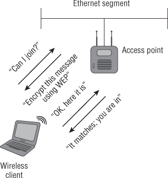
Figure 8.15 shows the four authentication frames used in shared-key authentication.
Figure 8.15 Packet capture of four frame exchange 802.11 shared-key authentication

IEEE 802.11 Association
IEEE 802.11 association takes place after a wireless device has been successfully 802.11 authenticated either by open system authentication or by shared-key authentication. In the association state, the authenticated device can pass traffic across the access point to the network infrastructure or other associated wireless devices, allowing access to resources that the device or user has permissions to access. After a device is authenticated and associated, it is considered to be part of the basic service set. A device must be 802.11 authenticated before it can be associated. Figure 8.16 illustrates the association process, and Figure 8.17 shows frames used during the association process.
Figure 8.16 Authentication and association
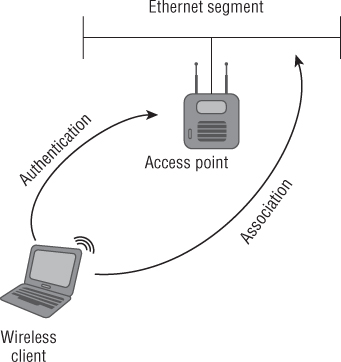
Figure 8.17 Packet capture of the association request and association response process

After successful association, the IEEE 802.11 authentication and association process is complete. Keep in mind that this is very basic access to the network using either open system authentication or WEP for authentication and encryption. After this process is complete, more sophisticated authentication mechanisms such as IEEE 802.1X/EAP (which provides user-based authentication) or preshared key (passphrase) can be used to secure the wireless network. These and other security components will be discussed in more detail in Chapter 9.
IEEE 802.11 Deauthentication and Disassociation
It is worthwhile to understand that the opposite of authentication and association can occur in a wireless LAN. These events are known as deauthentication and disassociation. Deauthentication occurs when an existing authentication is no longer valid. This can be caused by a wireless LAN device logging off from the current connection or roaming to a different BSS. A disassociation occurs when an association to an access point is terminated. This may occur when the associated wireless LAN device roams from one BSS to another. Both deauthentication and disassociation are notifications and not requests. Since neither can be refused by either side, they are both considered automatically successful from the sender's perspective. Unless IEEE 802.11w is implemented, deauthentication can also be a security issue. These frames can be used for denial of service attacks or to hijack a wireless device. Both deauthentication and disassociation frames are management frames. Figure 8.18 shows how disassociation and deauthentication frames would look on a packet analyzer.
Figure 8.18 Packet capture of disassociation and deauthentication frames

![]()
The Distribution System
In wireless LAN technology, the distribution system (DS) is the common network infrastructure to which wireless access points are connected; it can be wired or wireless. In most cases this would be an Ethernet segment. In this capacity, the access point acts like a Layer 2 translational bridge. A translational bridge is defined as a device used to connect two or more dissimilar types of LANs together, such as wireless (IEEE 802.11) and Ethernet (IEEE 802.3). From a receiver's perspective, this allows an access point to take information from the air (the communication medium in wireless networking) and make a decision either to send it back out to the same wireless radio or to forward it across to the distribution system. An access point can do this because it has enough intelligence to determine if a data frame is destined to be sent to the distribution system or if it should stay on the originating wireless side of the network. This is possible because the access point knows whether a device is part of the wireless LAN side through the authentication and association methods mentioned earlier. Figure 8.19 shows an example of a distribution system.
Figure 8.19 Two access points connected to a common distribution system, in this case IEEE 802.3, Ethernet
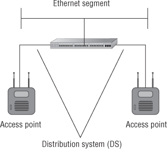
The distribution system is a network segment that consists of one or more connected basic service sets. As mentioned earlier, according to the original IEEE 802.11 standard, one or more interconnected basic service sets make up an extended service set. The distribution system allows wireless LAN devices to communicate with resources on a wired network infrastructure or to communicate with each other through the wireless medium. Either way, all wireless frame transmissions will traverse through an access point.
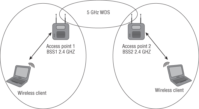
In some cases it may be feasible and justified to use a wireless distribution system (WDS). Unlike the wired distribution system mentioned earlier, a wireless distribution system will connect basic service sets together using wireless LAN technology. Typically the best way to use a WDS is to use two different radio technologies in the same access points. For example, using the 2.4 GHz band for wireless device access and the 5 GHz band for the distribution system will limit contention and provide associated devices a better experience because one radio is used for device access and the other creates the WDS. Figure 8.20 shows an example of a wireless distribution system.
Figure 8.20 Two dual-band access points used to create a wireless distribution system
Data Rates
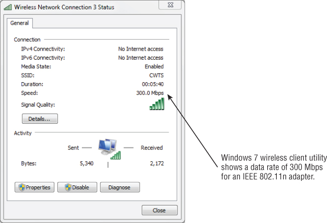
The speed at which wireless devices are designed to exchange information is known as the data rate. As mentioned in Chapter 5, “Physical Layer Access Methods and Spread-Spectrum Technology,” these rates will differ depending on the wireless standard, amendment, spread spectrum type, or Physical Layer technology in use. Table 8.1 shows data rates for various WLAN technologies. Data rates do not accurately represent the amount of information that is actually being transferred between devices and a wireless network. Figure 8.21 shows an 802.11a/g/n wireless LAN adapter in a notebook computer reading a data rate of 300 Mbps. To learn more about the actual amount of information transferred, see the next section, “Throughput.”
Table 8.1 Data rates based on spread spectrum type
| Standard/amendment | Technology | Data rates |
| 802.11 | FHSS | 1 and 2 Mbps |
| 802.11 | DSSS | 1 and 2 Mbps |
| 802.11b | HR/DSSS | 5.5 and 11 Mbps; 1 and 2 Mbps from DSSS |
| 802.11a | OFDM | 6, 9, 12, 18, 24, 36 and 48 Mbps |
| 802.11g | ERP-OFDM | 6, 9, 12, 18, 24, 36 and 48 Mbps |
| 802.11n | HT-OFDM | Up to 300 Mbps |
Figure 8.21 Windows 7 wireless configuration utility showing a data rate of 300 Mbps for an IEEE 802.11a/g/n wireless LAN adapter
Throughput
Unlike data rate (the maximum amount of information theoretically capable of being sent), throughput is the amount of information actually being correctly received or transmitted. Many variables affect the throughput of information being sent. Some of these include:
- Spread spectrum or Physical Layer technology type in use
- Radio frequency interference
- Number of wireless devices connected to an access point
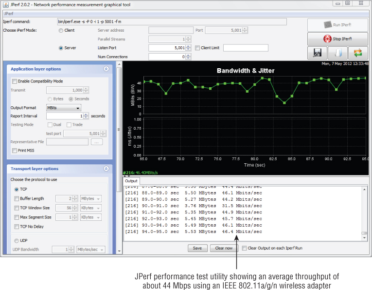
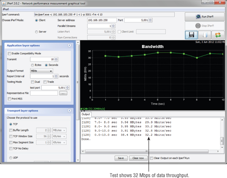
For example, an 802.11g wireless access point has a maximum data rate of 54 Mbps. With one user connected to this access point, chances are the best throughput that could be expected is less than 50 percent of the maximum, or about 20 Mbps. If more users connect to the same access point, the throughput for each user would be even less, because of the contention between users sharing the same wireless medium. Figure 8.22 shows an example of actual throughput for an 802.11a/g/n wireless LAN adapter.
Figure 8.22 Actual throughput of an IEEE 802.11a/g/n 300 Mbps wireless LAN adapter
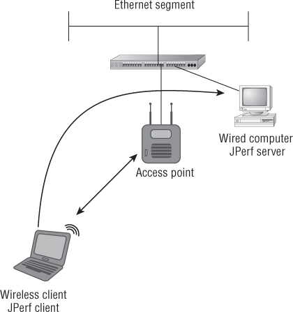
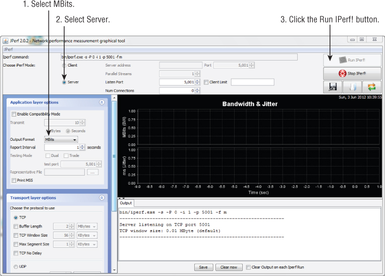
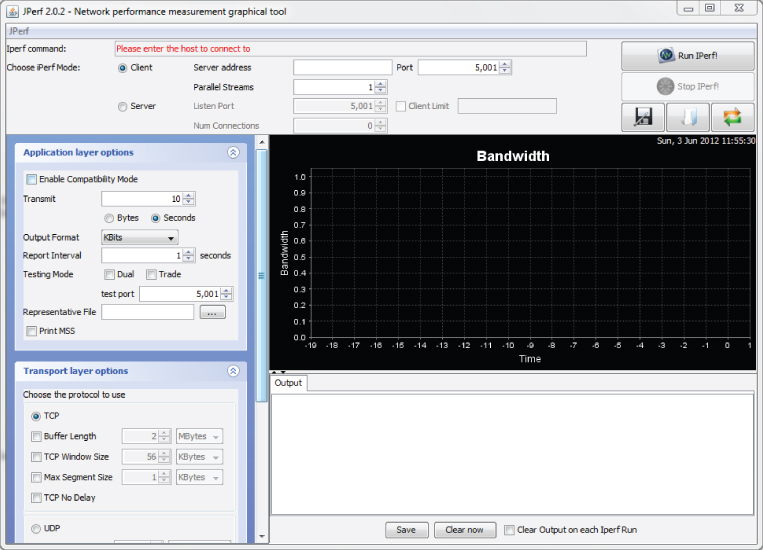
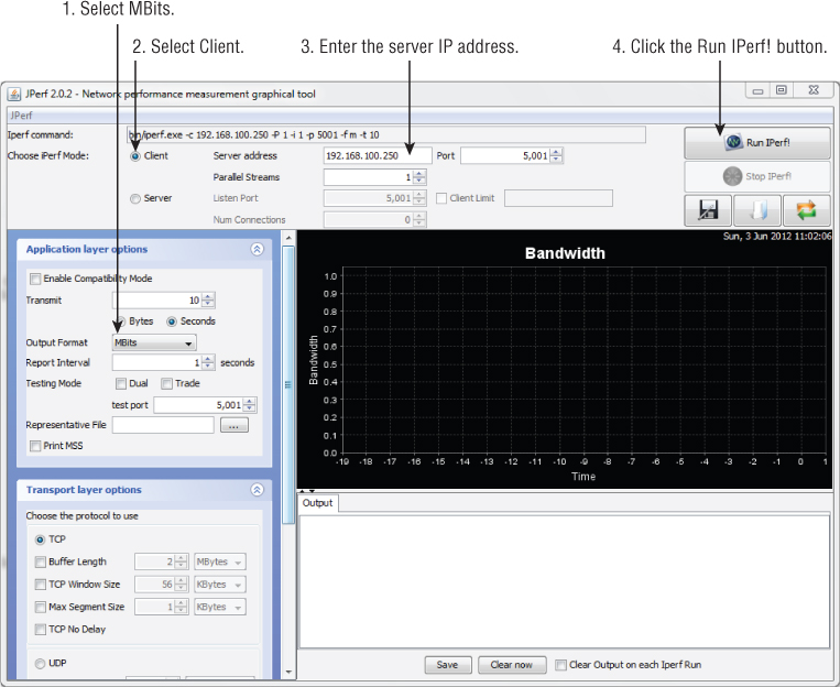
In Exercise 8.1 you will measure the throughput of your own wireless network.
- Two computers
- Java installed on both computers
- One wireless access point
- One Ethernet cable
- One wireless network adapter
- JPerf software (jperf-2.0.2.zip)

Dynamic Rate Switching
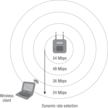
When a wireless device moves through the basic service area (BSA) or as the distance from the access point increases, the data rate will decrease. Conversely, as the wireless device moves closer to the access point, the data rate can increase. This is called dynamic rate switching (DRS), also known as dynamic rate shifting and even dynamic rate selection. This process allows an associated wireless device to adapt to the radio frequency in a particular location of the BSA. DRS is typically accomplished through proprietary mechanisms set by the manufacturer of the wireless device. The main goal of dynamic rate switching is to improve performance for the wireless device connected to an access point. As a wireless device moves away from an access point, the amount of received signal will decrease because of the free space path loss. When this occurs, the modulation type will change because the radio frequency signal quality is less and thus a lower data rate will be realized.
Remember from Chapter 5 that different data rates use different modulation technologies. Using a less complex modulation type at a lower data rate will provide better overall performance as the station moves away from the access point. Figure 8.23 illustrates how dynamic rate switching works. As the wireless device moves away from the access point, the data rate will decrease. Keep in mind the opposite is true as well. As a wireless device moves closer to an access point, the data rate will increase.
Figure 8.23 A graphical representation of dynamic rate switching
Wireless LAN Roaming or Transition
In wireless LAN technology, roaming is the term for what happens when a wireless device moves from one basic service set or access point to another. Roaming was not addressed in the original IEEE 802.11 standard. This process is typically accomplished in a proprietary manner based on how the manufacturer chooses to implement it. Manufacturers use different criteria to initiate roaming from one access point to another. There was an amendment to the IEEE 802.11 standard (IEEE 802.11F, Inter-Access Point Protocol) that was ratified in June 2003 as a recommended practice intended to address multivendor access point interoperability. However, this recommended practice was implemented by few if any manufacturers, and it was withdrawn by the IEEE 802 Executive Committee in February 2006. The next attempt to standardize roaming between access points is IEEE 802.11r. This driving force behind this amendment to the standard was to allow for fast secure transition with wireless voice devices.
When a wireless LAN device moves through a BSA and receives a signal from another access point, it needs to make a decision whether to stay associated with the current access point or to reassociate with the new access point. This decision when to roam is proprietary and based on specific manufacturer criteria. Some of these criteria manufacturers use are:
- Signal strength
- Signal-to-noise ratio
- Error rate
- Number of currently associated devices
When a wireless LAN device chooses to reassociate to a new access point, the original access point will hand off the association to the new access point as requested from the new access point. Keep in mind it is the wireless client device that initiates the move to a new access point. This move is done over the wired network or distribution system based on how the manufacturer implemented the roaming criteria. Figure 8.24 illustrates a notebook computer roaming from one access point to a new access point.
Figure 8.24 The roaming process for a wireless LAN
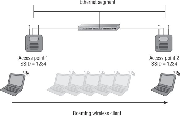
Figure 8.25 shows reassociation request and response frames in a packet analyzer.
Figure 8.25 Packet capture of the reassociation process

![]()
IEEE 802.11 Power Save Operations
Many wireless LAN devices are portable and use DC battery power to some degree. A wireless network adapter uses DC power to operate, and in some cases this could be a significant drain on the battery in the device. This is especially true with newer IEEE 802.11n wireless adapters that support MIMO technology. The original IEEE 802.11 standard addresses power saving operation. This power save operation is designed to allow a wireless LAN device to enter a dozing state in order to conserve DC power and extend battery life. If the wireless LAN device is plugged into a consistent power source such as an AC outlet, there is no reason to implement power save features. However, portable devices that are mobile and may not have access to an AC power source should consider using power save operations. The original IEEE 802.11 standard addressed two different power save modes: active mode (AM) and power save (PS) mode. In some cases, power save (PS) mode is considered legacy because the IEEE 802.11e amendment for quality of service addresses new, more efficient power save mechanisms. Although the original PS mode may be considered legacy, it is still widely used in many devices. As mentioned earlier in this chapter in the section “IEEE 802.11 Frame Types,” a data frame known as a null function frame is used with power management and does not carry any data but is used to inform the access point of a change in power state.
Active Mode
In active mode (AM) a wireless LAN device or station (STA) may receive frames at any time and is always in an “awake” state. In this case, the wireless LAN device is not relying on battery power; thus, there is no reason for the device to assume a low power state, and it will never doze. Some manufacturers refer to active mode as continuous aware mode (CAM).
Power Save Mode
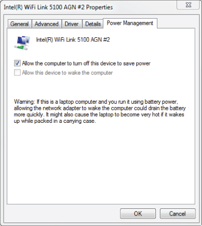
In power save (PS) mode, the wireless LAN device or station (STA) will doze or enter a low power state for very short periods of times. At specific time intervals, the device will “listen” for selected beacons and determine if any data is waiting for it (buffered) at the access point. The beacon frame contains information for associated devices regarding power save. When a wireless LAN device associates to an access point, the device receives what is known as an association ID (AID). The association ID is a value that will represent that device in various functions, including power save mode. The beacon frame contains an indicator for each AID associated device to let wireless devices know whether they have data waiting for them or buffered at the access point. If it is determined that the access point does have data buffered for a specific device, the device will send a control frame message (PS-Poll frame) to the access point to request the buffered data. Figure 8.26 shows where power save mode can be set in the advanced settings of the wireless adapter device driver.
Figure 8.26 The driver settings for an Intel 5100 IEEE 802.11a/g/n wireless adapter and power save mode setting
Power save mode may cause some amount of overhead for the wireless LAN device, and there is a trade-off in performance. With power save mode enabled, the battery life will be extended; however, performance will suffer to some degree because the device will not be available to receive data continuously. The device will only be able to receive buffered data during the “awake” state. Power save mode is common in applications where battery conservation is important, such as barcode scanners, voice over Wi-Fi phones, and other handheld devices.
![]()
Automatic Power Save Delivery
The IEEE 802.11e Quality of Service amendment to the standard fueled the need for more efficient power save mechanisms in wireless networking. Depending on the implementation and requirements, legacy power save modes may not be efficient enough to work with applications that use QoS, such as voice and video. Automatic power save delivery (APSD) differs from the original power save mode in that a trigger frame will wake a device in order to receive data. APSD is a more efficient way of performing power save functions. It works well with time-bound applications that are subject to latency, such as voice and video.
IEEE 802.11 Protection Mechanisms
In order to allow newer, faster wireless LAN technology such as 802.11g and 802.11n devices to communicate with older, slower wireless devices, technology called protection mechanisms was designed to allow for backward compatibility. The mechanisms available depend on which amendment to the standard is used. Protection mechanisms will provide the backward compatibility needed to allow different technologies to coexist in the same radio frequency space.
There are two broad categories of protection mechanism:
- Extended rate physical (ERP) protection mechanism for IEEE 802.11g networks
- High throughput (HT) protection mechanism for IEEE 802.11n networks
Each category includes several modes for specific situations.
IEEE 802.11g Extended Rate Physical Protection Mechanisms
In order for IEEE 802.11g and IEEE 802.11b devices to coexist in the same basic service area, the wireless access point must use extended rate physical (ERP) protection. Most manufacturers of IEEE 802.11 wireless LAN equipment will provide options when it comes to coexistence. These options usually include the capability to set an access point to one of three modes:
- IEEE 802.11b only mode: DSSS and HR/DSSS
- IEEE 802.11g only mode: ERP-OFDM
- IEEE 802.11b/g mixed mode: DSSS, HR/DSSS, and ERP-OFDM
IEEE 802.11b-Only Mode
This mode requires setting an access point to operate in 802.11b-only mode. This involves disabling all the IEEE 802.11g ERP-OFDM data rates of 6, 9, 12, 18, 24, 36, 48, and 54 Mbps and allowing only DSSS data rates of 1 and 2 Mbps and HR/DSSS rates of 5.5 and 11 Mbps. Enabling this mode limits the maximum data rate to 11 Mbps. Setting an access point to this mode has limited applications such as using legacy IEEE 802.11b-only capable devices, for example.
IEEE 802.11g-Only Mode
This mode is the opposite of 802.11b-only mode. It disables all of the IEEE 802.11b DSSS and HR/DSSS data rates of 1, 2, 5.5, and 11 Mbps, and it allows the IEEE 802.11g ERP-OFDM data rates of 6, 9, 12, 18, 24, 36, 48, and 54 Mbps. This operation mode is useful in an environment where backward compatibility to 802.11b is not required, such as an environment where all devices connecting have IEEE 802.11g capability, and the throughput needs to be maximized; thus there are no IEEE 802.11b devices in use.
IEEE 802.11b/g Mixed Mode
Most deployments in the 2.4 GHz ISM band use this mode for communications. This allows devices that support the IEEE 802.11g amendment and IEEE 802.11b devices to operate together in the same BSA and associated to the same access point. As mentioned in Chapter 2, “Introduction to Wireless Local Area Networking,” throughput will decrease when IEEE 802.11b devices and IEEE 802.11g devices are both associated to the same access point.
Extended Rate Physical (ERP) mixed mode uses control frames to reserve the wireless medium. Two options are available:
Both RTS/CTS and CTS-to-Self control frames allow wireless devices using different Physical Layer technologies to share the wireless medium and help to avoid collisions. These control frames specify how much time is needed for a frame exchange between the transmitter and a receiver to complete. This time value is processed by all devices in the basic service area that are not part of the frame exchange. Once this time has expired, the wireless medium is considered clear.
IEEE 802.11n High-Throughput Protection Mechanisms
IEEE 802.11n devices operate in either the 2.4 GHz or the 5 GHz band. Backward compatibility for IEEE 802.11a/b/g devices needs to be taken into consideration. The IEEE 802.11n amendment identifies several different modes for high-throughput (HT) protection mechanisms. These mechanisms are known as HT protection modes and are a set of rules that devices and access points will use for backward compatibility:
- Mode 0-Greenfield mode
- Mode 1-HT nonmember protection mode
- Mode 2-HT 20 MHz protection mode
- Mode 3-HT mixed mode
These modes are constantly changing based on the radio frequency environment and associated wireless devices. The goal with IEEE 802.11n wireless networks is to get to Mode 0-Greenfield mode. With today's wireless networks and WLAN technology, we are more than likely at Mode 3-HT mixed mode or possibly even one of the other two modes in most cases.
Mode 0-Greenfield Mode
Mode 0 or Greenfield mode allows high-throughput (HT) devices only. These HT devices must also share operational functionality and they must match; for example, they must all support 20 MHz or 20/40 MHz channels only. If an IEEE 802.11n (HT) access point is set to 20/40 MHz channel width and a client capable of only 20 MHz wide channels associates, the connection is not considered Greenfield mode. Mode 0 does not allow IEEE 802.11a/b/g devices using the same RF channel. IEEE 802.11a/b/g devices will not be able to communicate with an access point in Greenfield mode. Transmissions from these devices will cause collisions at the access point, causing some degradation in throughput because it is seen by the HT system as radio frequency interference. Greenfield mode is what we as wireless network designers and administrators are working toward achieving, but it may be some time before we are there because of backward compatibility and legacy wireless devices.
Mode 1-HT Nonmember Protection Mode
All devices in Mode 1 or HT nonmember protection mode must be HT-capable. When a non-HT device—that is, an IEEE 802.11a/b/g access point or wireless client device—is within the hearing range of the HT access point and on the same 20 MHz channel or one of the 20/40 MHz wide channels, this protection mode will be activated.
Mode 2-HT 20 MHz Protection Mode
All devices in Mode 2 or HT 20 MHz protection mode must be HT-capable as well. The operation of this protection mode is based on the fact that 802.11n devices can use 20 MHz or 20/40 MHz wide channels. Mode 2 means that at least one 20 MHz HT station is associated with the HT 20/40 MHz access point and that the access point provides compatibility for 20 MHz devices.
Mode 3-HT Mixed Mode
Mode 3 or HT mixed mode is used if one or more non-HT stations are associated in the BSS. This mode allows backward compatibility with non-802.11n or IEEE 802.11a/b/g wireless devices. This is the likely the most common mode for IEEE 802.11n HT networks today because of the need for backward compatibility and the legacy IEEE 802.11 wireless devices that are still in use on most wireless networks.
Additional HT Protection Modes
Two other HT protection modes are also available:
- Dual CTS is a Layer 2 protection mechanism that is used for backward compatibility between IEEE 802.11n HT and IEEE 802.11a/b/g devices.
- Phased coexistence operation (PCO) is an optional BSS mode with alternating 20 MHz and 20/40 MHz phases controlled by a PCO-capable access point.
Summary
Wireless LANs can operate in two modes: either ad hoc mode, which means no access points are used, or infrastructure mode, where an access point provides a central point of communication for the wireless LAN devices. In this chapter, we looked at these modes of operation as well as the service sets IEEE 802.11 networks use. We looked at the three configurations for wireless LANs:
- Independent basic service set (IBSS)
- Basic service set (BSS)
- Extended service set (ESS)
In this chapter we discussed the configuration of each, along with some of the advantages and disadvantages of each configuration—from an IBSS, which uses no access points, to a BSS or ESS, which uses one or many access points. Some of the configuration parameters, such as SSID and radio frequency channel, and how they are used were also explained. Some of these acronyms are very close in spelling and sound similar when spoken. It is important to understand the differences among the following abbreviations:
- Service set identifier (SSID)
- Extended service set identifier (ESSID)
- Basic service set identifier (BSSID)
- Independent basic service set (IBSS)
- Basic service set (BSS)
- Extended service set (ESS)
- Basic service area (BSA)
For example, SSID is the name of the wireless network, and the BSSID is the unique identifier MAC address of the AP radio.
In addition to explaining the different configurations and terminology used, we looked at the processes wireless devices use to connect to and become part of a wireless LAN, including:
- Wireless discovery
- Passive scanning
- Active scanning
- IEEE 802.11 authentication
- IEEE 802.11 association
The discovery processes of passive scanning (listening for beacons) and active scanning (joining a wireless LAN) are important parts of starting the connection process. This continues with 802.11 authentication—in most cases open system—and the 802.11 association process. Once these processes are complete, the device finally becomes part of the wireless network, enabling it to pass traffic across to the access point to the network infrastructure.
We also saw the components and technology that play a role with IEEE 802.11 wireless networks, such as:
- Distribution system (DS)
- Wireless distribution system (WDS)
- Data rate (what is advertised)
- Throughput (what is actual)
Both a wired distribution system, in most cases Ethernet, and a wireless distribution system using radios and access points provide connectivity for wireless infrastructure. We looked at the differences between data rate and throughput. It is important to understand that an access point may have a data rate of 54 Mbps or even up to 600 Mbps, but throughput (the actual data transmission rate) is typically less than half of the data rate. Because wireless LANs are contention based, data throughput will be even less when more devices connect to the network.
Dynamic rate switching—a client transferring more or less data depending on the proximity from an access point as well as roaming or moving through the basic service areas and being able to maintain connectivity—was also discussed in this chapter. Finally, the chapter covered the important topics of power save mode and protection mechanisms. With power save mode, a wireless LAN device is able to extend battery life by entering into a low-power state or “doze” for very short periods of time. This permits the device to consume less battery power, therefore allowing connectivity for longer periods of time without changing or recharging the battery. The modes discussed were:
- Active mode
- Power save mode (PS)
- Automatic power save delivery (APSD)
It is beneficial to understand the differences in power save capabilities among these modes.
Lastly, we discussed IEEE 802.11 protection mechanisms and the importance of these methods in order to provide backward compatibility and coexistence to older technology devices:
- Extended rate physical (ERP) protection for IEEE 802.11g
- High throughput (HT) protection for IEEE 802.11n
We looked at some highlights of both protection mechanism technologies for IEEE 802.11g and 802.11n networks.
Exam Essentials
Review Questions
1. When a wireless LAN device listens for beacon frames, it is participating in which phase?
A. Power save
B. Passive scanning
C. Active scanning
D. Authentication
2. You are a sales engineer connected to an IEEE 802.11a access point with a mobile computer. As you move away from the access point, the connection speed slows to the next lowest supported data rate. The change in data rate is described by which term?
A. Dynamic frequency selection
B. Transmit power control
C. Dynamic rate switching
D. Transmit save mode
3. An independent basic service set (IBSS) consists of how many access points?
A. 0
B. 1
C. 2
D. 4
4. Wireless LAN devices in an 802.11a peer-to-peer network will connect to which device(s)?
A. An access point
B. 802.11g client devices
C. 802.11a client devices
D. A wireless switch
5. As a device moves away from an access point, which of the following is true regarding dynamic rate switching?
A. Data rate decreases
B. Output power decreases
C. Data rate increases
D. Output power increases
6. A service set identifier (SSID) has a maximum limit of how many characters or octets?
A. 8
B. 16
C. 32
D. 128
7. You are a technical support engineer and receive a call from a customer regarding a problem with their wireless network connection. The building has an ESS network with five 802.11g access points. The customer claims that when they move from their office to a conference room using the 802.11g network they lose their connection and cannot connect to the access point in the conference room. Which is the most likely cause for this user to lose their connection when they roam on the wireless network?
A. Different RF channel
B. Mismatched SSID
C. Different BSSID
D. Mismatched association
8. A beacon frame advertises information about the wireless network. A beacon frame is what type of frame?
A. Data
B. Control
C. Management
D. Detail
9. In order for a wireless client to become completely part of the basic service set, it must first _____ and then _____
A. Associate, authenticate
B. Authenticate, associate
C. Deauthenticate, authenticate
D. Disassociate, authenticate
10. The process in which a wireless LAN client connection moves from one access point to another is called _____.
A. Reauthentication
B. Roaming
C. Rebuilding
D. Roving
11. In order to set up an ad hoc network, a user must know which two parameters? (Choose two.)
A. SSID
B. BSSID
C. Channel
D. MAC address
E. Protection mode
12. The open system authentication process uses how many frames?
A. One
B. Two
C. Three
D. Four
13. You are a help desk support technician at a retail department store and you receive a call from a manager in the administrative offices. He complains that the performance of his 802.11g notebook computer decreases several times throughout the day. Upon visiting the customer, you realize several people are performing inventory using 802.11b barcode scanners in the adjacent room. What is most likely the cause of the poor performance for the manager's notebook computer?
A. Association
B. Authentication
C. ERP protection
D. HT protection
14. Which items describe a service set identifier (SSID)? (Choose two.)
A. 32 characters maximum
B. 64 characters maximum
C. Is case sensitive
D. Is not case sensitive
15. A basic service set identifier (BSSID) is the unique identifying MAC address of the _____.
A. AP radio
B. AP Ethernet port
C. Router
D. Client
16. When an IEEE 802.11g wireless LAN consists only of wireless client stations, the network is operating as what type of basic service set?
A. Active
B. Independent
C. Passive
D. Infrastructure
17. You are a technical support engineer and provide help desk support for the network in a manufacturing company. You receive a call from the sales manager, who wants to know how power save operations should be set up on her notebook computer to optimize the system performance. The notebook computer is plugged into an AC power source and rarely used on battery. Which mode would you recommend her to set on the wireless adapter?
A. Power save mode
B. Association mode
C. Active mode
D. Passive mode
18. According to the IEEE 802.11 standard, an extended service set (ESS) consists of how many interconnected basic service sets?
A. One or more
B. Two or more
C. Three or more
D. Four or more
19. The IEEE 802.11 association process happens after which phase?
A. Authentication
B. Distribution
C. Deauthentication
D. Reauthentication
20. A basic service set (BSS) consists of how many access points?
A. Zero
B. At least one
C. At least two
D. At least four