
Chapter 5
Physical Layer Access Methods and Spread-Spectrum Technology
The following CWTS exam objectives are covered in this chapter:
- 3.4 Define and differentiate between the following physical layer wireless technologies
- 802.11b HR/DSSS
- 802.11g ERP
- 802.11a OFDM
- 802.11n HT
It is important to understand how digital data is sent from one device to another. Whether on a wired network or a wireless network, an access method is used to transfer this type of electronic information. Two common access methods are CSMA/CD and CSMA/CA. The type of medium in use—wired or wireless—will determine which of these two access methods is best suited for the application. You saw in previous chapters that wireless LANs use radio frequencies with air as the communication medium. This chapter will discuss the various techniques and methods used to get digital computer data from one device to another using spread-spectrum and other physical layer modulation technologies.
It is important to understand that different spread-spectrum technologies such as FHSS, DSSS, and HR/DSSS will allow for various data rates. The spread-spectrum or other physical layer technology used will determine the maximum amount of data transfer as well as the resilience to noise and other interfering sources. We will look at the 802.11 channels, the number of channels available, channel spacing, and the frequencies of the unlicensed radio frequency bands used with wireless networking. We will also discuss the implications of overlapping channels and interference. Finally, this chapter will discuss co-location of different technologies used in various amendments to the standard as well as interference from wireless LANs and other sources, including WPANs.
![]()
Network Access Methods
Network access methods allow devices connected to a common infrastructure to communicate and transmit data across a network medium from one device to another. Several different types of network access methods are used in computer networks. The two types we will discuss in this chapter are:
- Carrier Sense Multiple Access/Collision Detection (CSMA/CD)
- Carrier Sense Multiple Access/Collision Avoidance (CSMA/CA)
Because Ethernet networks have the capability to detect collisions, 802.3 Ethernet networks use CSMA/CD as the access method. Devices on a wireless LAN do not have the capability to detect collisions; therefore 802.11 wireless LANs use CSMA/CA for the access method. Since multiple wireless devices can use an access point at the same time, wireless devices that connect to an access point are competing to share the medium; therefore, it is important to control the medium in order to minimize collisions. The CSMA/CA process provides this control.
Detecting Network Traffic Collisions with CSMA/CD
802.3 Ethernet networks use CSMA/CD to share the medium. The name of this access method describes how it functions.
The abbreviation CSMA/CD is broken down as follows:
- Carrier Sense—Devices sense the medium (in this case, Ethernet cable) to see if it is clear (no data being transmitted).
- Multiple Access—Many devices accessing the medium at the same time.
- Collision Detection—Detecting collisions that occur on the medium during the transmission of data.
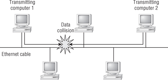
CSMA/CD is a contention-based media access control method that Ethernet devices use to share the medium. This method allows only one device to transmit at any one time.
In computing terminology, contention is defined as multiple devices competing for a chance to send data on the network. CSMA/CD functions like this:
This contention of the Ethernet segment is one reason for decreased data throughput of the transmitting devices. Figure 5.1 demonstrates CSMA/CD with desktop computers connected to an Ethernet segment.
Figure 5.1 Computers connected to Ethernet cable using CSMA/CD
Avoiding Network Traffic Collisions with CSMA/CA
Wireless LANs use CSMA/CA to share the medium. The main difference from CSMA/CD is the CA—collision avoidance. Just as in CSMA/CD, the abbreviation CSMA/CA gives an idea of how it functions:
- Carrier Sense—Sensing the medium, in this case the air
- Multiple Access—Many devices accessing the medium at the same time
- Collision Avoidance—Avoiding collisions that may occur on the medium during transmission
Because wireless LAN devices have no way to detect collisions, the CSMA/CD access method is not an adequate solution for wireless LAN communications. If wireless LANs were to use CSMA/CD, collisions would occur at the wireless access point and all data would be lost. At this point, a transmitting device would not know that it should retransmit the information, because the receiving device would be unaware that a collision occurred; the result would be very poor performance.
Instead of detecting transmission collisions, CSMA/CA uses mechanisms that attempt to avoid collisions. Although these mechanisms impose some overhead, the overall benefit is better data throughput because data collisions are minimized. This overhead occurs because devices use “countdown timers” that require them to wait for periods of time before they are able to transmit again. This helps to avoid data collisions.
Reserving Time for Data Transmission Using Distributed Coordination Function
One of the access methods wireless LAN devices use to communicate is known as distributed coordinated function (DCF). This method of access employs a contention period for devices competing to send data on the network. This collision avoidance mechanism is part of a detailed process requiring certain criteria to be met in order for a frame (a Layer 2 digital transmission unit) to be transmitted across the medium. In the case of wireless LAN technology, this medium is the air, using radio frequencies (RF).
To avoid collisions, the devices are required to:
- Detect the RF energy of other devices transmitting, a technique known as Clear Channel Assessment (CCA).
- Announce how much time is required for the frame exchange to occur allowing other stations read the duration field and set their Network Allocation Vector (NAV).
- Wait for a predetermined period of time between frames, a technique known as interframe spacing.
- Back off and retry if the medium is busy, a technique known as the random backoff timer via the contention window.
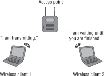
In short, these devices are reserving the medium so that transmissions can take place and avoid collisions. Figure 5.2 illustrates wireless LAN devices using CSMA/CA for an access method.
Figure 5.2 Wireless LAN devices using CSMA/CA and DCF
![]()
Effects of Half Duplex on Wireless Throughput
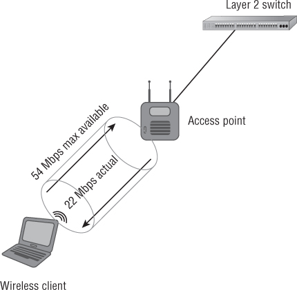
As discussed in Chapter 3, “Wireless LAN Infrastructure Devices,” wireless LANs use half duplex communication. To review, half duplex in computer terminology is defined as two-way communication that occurs in only one direction at a time. Communication only one way at a time means less data throughput for the connected device(s). Half-duplex communication is part of the reason why in wireless LANs the amount of data being transferred is sometimes less than half of the advertised data rate; collisions and additional overhead are other factors to consider. An 802.11b device may only get 5.5 Mbps or less data transfer even though this technology is rated at 11 Mbps. On a good day, 802.11a or 802.11g devices will also average less than half of the advertised data rates. Figure 5.3 shows the half-duplex communication method and some of the effect it has on throughput. The data rate in this example is 54 Mbps, but the throughput is less than half of that, about 22 Mbps. The newest IEEE amendment, 802.11n, uses MIMO technology and has a potential maximum data rate of up to 600 Mbps. However, many of the client devices available today have a maximum of about 300–450 Mbps. The actual throughput can be as low as 30 Mbps.
Figure 5.3 Half-duplex operation has some effect on overall data throughput.
Narrowband vs. Spread-Spectrum Communication
Narrowband and spread-spectrum are two examples of how devices can communicate using radio frequency.
One example of narrowband communication is an FM radio station. FM radio stations use licensed frequency ranges that are tuned to a specific radio frequency in the FM band. A radio station can transmit a signal at a high power of tens of thousands of watts in a very narrow frequency. Depending on the conditions, a receiver can hear the station for tens or even possibly hundreds of miles.
Figure 5.4 shows the high amount of output power over a narrowband frequency of a potential FM radio station.
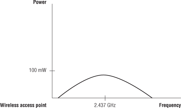
In contrast, spread-spectrum technology uses low power over a wider range of frequency. Figure 5.5 illustrates how a spread spectrum–capable access point uses low power over a wide frequency range.
Figure 5.4 Narrowband frequency—high power, narrow frequency
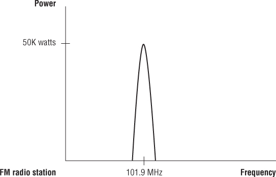
Figure 5.5 Spread-spectrum technology—low power, wide frequency
Spread-Spectrum Technology
Two types of spread-spectrum technology were specified in the original IEEE 802.11 wireless LAN standard ratified in 1997:
- Frequency-hopping spread spectrum (FHSS)
- Direct-sequence spread spectrum (DSSS)
These spread-spectrum technologies communicate in the 2.4 GHz ISM frequency range. There are advantages and disadvantages to each of these spread-spectrum types.
Spread-spectrum technologies take the digital information generated by a computer (ones and zeros) and, through the use of modulation technologies, send it across the air between devices using radio frequency (RF).
In order for devices to communicate effectively and understand one another, they must be using the same spread-spectrum and modulation technology. This would be analogous to two people trying to talk with each other. If the two people don't know the same language, they will not be able to understand each other and a conversation could not take place.
Frequency-Hopping Spread Spectrum
Frequency-hopping spread spectrum (FHSS) is used in a variety of devices in computer technology and communications. FHSS was used by many early adopters of wireless networking, including computers, barcode scanners, and other handheld or portable devices. Although defined in the original IEEE 802.11 standard, this technology is considered “legacy” (out of date) in IEEE 802.11 wireless networking. However, FHSS is still common today in many devices such as cordless telephones and IEEE 802.15 wireless personal area networks (WPANs), including Bluetooth mice, cameras, phones, wireless headsets, and some older wireless LAN technology devices. Bluetooth technology using FHSS is comparatively slower than newer IEEE 802.11 wireless communications.
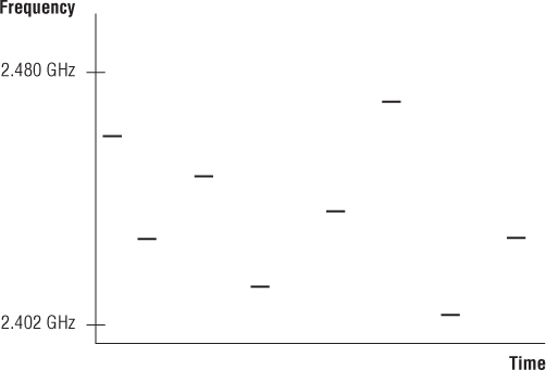
FHSS operates by sending small amounts of information such as digital data across the entire 2.4 GHz ISM band. As the name implies, this technology changes the frequency (“hops”) constantly in a specific sequence or hopping pattern and remains on a frequency for a specified amount of time known as the dwell time. The dwell time value will depend on the local regulatory domain where the device is used. In the United States, for example, the Federal Communications Commission allows a maximum dwell time of 400 milliseconds. A transmitter and receiver will be synchronized with the same hopping sequence, therefore allowing the devices to communicate.
The data rate for IEEE 802.11 FHSS is only 1 and 2 Mbps, which is considered slow by modern computer applications. However, the data rate is more than adequate for some applications. For example, various wireless devices in retail and manufacturing used FHSS in handheld scanners and other portable technology for many years. The cost of upgrading these devices to support higher data rates was prohibitive and unnecessary in many cases, and so until recently they were still used in such environments. Figure 5.6 illustrates what FHSS would look like if you could see the RF hopping through the band.
Figure 5.6 FHSS hops the entire 2.4 GHz ISM band.
802.11 Direct-Sequence Spread Spectrum
Direct-sequence spread spectrum (DSSS) is a spread-spectrum technology used with wireless LANs and defined by the original IEEE 802.11 standard. Like FHSS, DSSS supports data rates of 1 and 2 Mbps and is considered slow by today's computer networking requirements.
DSSS uses special techniques to transmit digital data (ones and zeros) across the air using radio frequency (RF). This is accomplished by modulating or modifying the radio frequency characteristics such as phase, amplitude, and frequency (see Chapter 6, “Radio Frequency Fundamentals for Wireless LAN Technology”).
In addition to modulation, DSSS uses technology known as a spreading code to provide redundancy of the digital data as it traverses through the air. The spreading code transmits information on multiple subcarriers, and the redundancy helps the receiver detect transmission errors due to interference. Subcarriers are smaller segments of the radio frequency channel that is in use. This spreading of information across the 22 MHz–wide channel is what helps makes DSSS resilient to interference. This spreading code technology allows the receiver to determine if a single bit of digital data (symbol) received is a binary 0 or binary 1. Depending on the data rate, the transmitter and receiver understand the spreading code in use and therefore are able to communicate.
An example of a coding technique is Barker code. Barker code is used as the spreading code for DSSS at the data rates of 1 and 2 Mbps. IEEE 802.11 wireless LANs can use this 11 “chip” spreading code for communications. Each digital data bit (binary 1 or 0) is combined with the set Barker code through what is called an exclusive OR (XOR) process. XOR is a way of combining binary data bits in digital electronics. The result then spreads the binary 0 or 1 over a 22 MHz wide channel, helping to make it resilient to radio frequency interference. Since both the transmitter and receiver understand the same code, they would be able to determine the information that was sent across the air.
DSSS operates within a range of RF frequency also known as a channel. The channel is defined by its center frequency; that is, Channel 1 is 2.412 GHz on center, Channel 2 is 2.417 GHz on center, and so on. Each channel in the 2.4 GHz ISM band is separated by 5 MHz on center. Unlike narrowband communication, which operates on a single narrow frequency, a DSSS channel is 22 MHz wide and is one of 14 channels in the 2.4 GHz to 2.5 GHz ISM band. The country and location of the device will determine which of the 14 channels are available for use in that specific area.
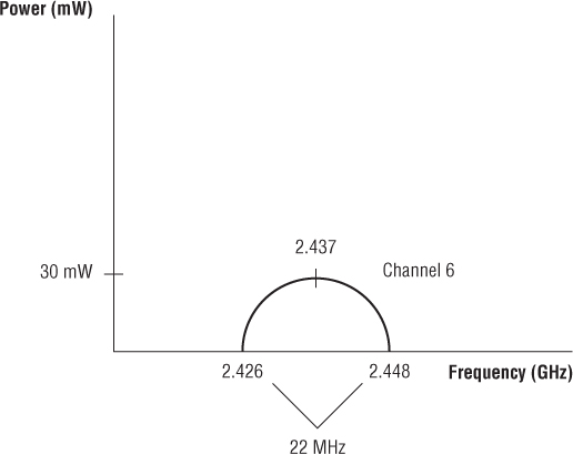
Figure 5.7 shows that channel 6 is 22 MHz wide in the ISM unlicensed RF band.
Figure 5.7 DSSS is limited to a 22 MHz–wide channel in the 2.4 GHz ISM band. Each channel for DSSS is 5 MHz on center.
![]()
802.11b High Rate/Direct-Sequence Spread Spectrum
High rate/direct-sequence spread spectrum (HR/DSSS) is defined in the IEEE 802.11b amendment to the IEEE 802.11 standard. HR/DSSS (802.11b) introduced higher data rates of 5.5 and 11 Mbps. At the time this amendment was released, because of the higher data rates this technology helped fuel the acceleration of IEEE standards based on wireless LAN technology. The desire for 802.11 technology grew as the availability became greater and the cost decreased.
Like DSSS, HR/DSSS uses one of fourteen 22 MHz wide channels to transmit and receive digital computer data. The main difference between these two technologies is that HR/DSSS supports higher data rates of 5.5 Mbps and 11 Mbps.
HR/DSSS (802.11b) also uses a different spreading code or an encoding technique than DSSS. HR/DSSS uses complementary code keying (CCK) for transmitting data at 5.5 and 11 Mbps. The detailed operation of CCK is beyond the scope of this book.
IEEE 802.11 DSSS and HR/DSSS Channels
DSSS and HR/DSSS operate in the 2.4 GHz industrial, scientific, and medical (ISM) license free band. This band has 14 available channels. Depending on the country and location, all 14 channels may not be available. Table 5.1 shows the 14 available channels in the 2.4 GHz ISM band for a few different countries.
Table 5.1 14 available channels in 2.4 GHz ISM band
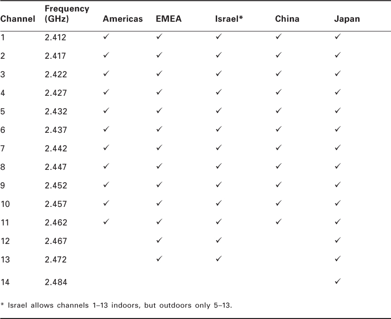
Figure 5.8 shows the 14 available channels and the amount of overlap in the 2.4 GHz ISM band.
Figure 5.8 The 2.4 GHz ISM band allows 14 channels.
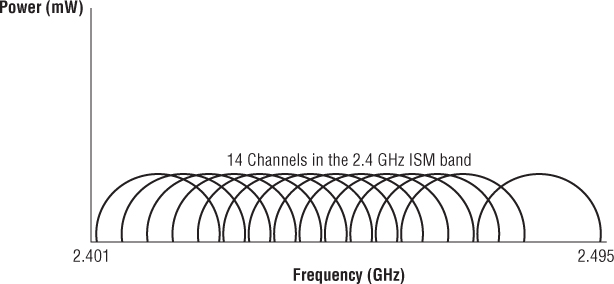
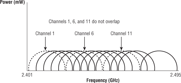
Of these 14 channels, mathematically there are only 3 adjacent nonoverlapping channels, with the exception of channel 14. According to the IEEE 802.11-2012 standard, “Channel 14 shall be designated specifically for operation in Japan.” Channel 14 is separated by 12 MHz on center from Channel 13, whereas Channels 1–13 are separated by 5 MHz on center of each channel. There are 3 MHz of separation where the radio frequency of one channel ends and the next adjacent nonoverlapping channel begins. For example, Channel 1 and Channel 6 are adjacent nonoverlapping channels. Channel 1 ends at 2.423 GHz and Channel 6 begins at 2.426 GHz. Mathematically this is a separation of 3 MHz. This means that three access points can be co-located in the same physical space without overlapping channel interference. However, there is still theoretically a small amount of overlapping RF or harmonics between these two channels. This small level of overlap is not large enough to cause any real interference issues. Figure 5.9 illustrates 3 of the first 14 channels that do not overlap in the 2.4 GHz ISM band.
Each DSSS channel is 22 MHz wide. Using spread-spectrum technology, a 22 MHz–wide channel helps add resiliency to interference for data transmissions and gives the capability to move large amounts of data with a small amount of power. Some early IEEE 802.11 devices included barcode scanners, and they worked with limited battery life. Using a spreading technology instead of narrowband technology helped to conserve battery life and increased the use of IEEE 802.11 devices as a whole.
Figure 5.9 3 Nonoverlapping channels possible in the 2.4 GHz ISM band
IEEE 802.11g Extended Rate Physical
The IEEE 802.11g amendment was released in 2003 and introduced technology that allowed for higher data rates for devices and operation in the 2.4 GHz ISM band. The objective of this amendment was to allow for these higher data rates (up to 54 Mbps) using orthogonal frequency division multiplexing (OFDM) and still maintain backward compatibility with existing 802.11b technology and devices. This technology, known as Extended Rate Physical (ERP), builds on the data rates of 1, 2 Mbps DSSS (802.11) and 5.5, 11 Mbps HR/DSSS (802.11b). The 802.11g amendment addresses several compatibility operation modes:
- ERP-DSSS/CCK
- ERP-OFDM
- ERP-PBCC (Optional)
- DSSS-OFDM (Optional)
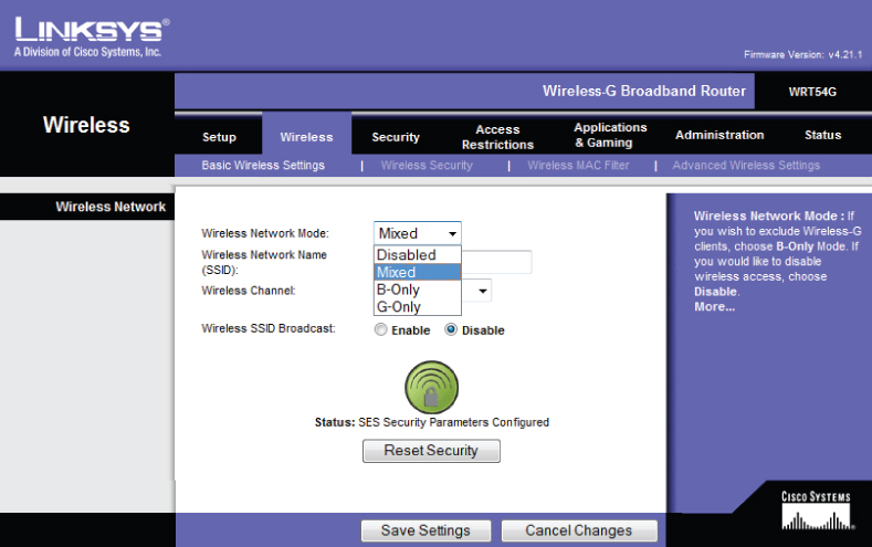
The 802.11g amendment required support for ERP-DSSS/CCK and ERP-OFDM. This allowed for both the 802.11b data rates of 1, 2, 5.5, and 11 Mbps and the new OFDM data rates of 6, 9 ,12, 18, 24, 36, 48, and 54 Mbps. Manufacturers of wireless LAN equipment implement this in various ways. In a graphical user interface, there may be a drop-down menu that allows a user to select a specific operation mode such as mixed mode, b/g mode, b-only mode, and so on. Another possibility is to select the individual data rates using radio buttons. For manufacturers that provide a command-line interface (CLI) option, the appropriate commands would need to be executed in order to enable or disable the desired data rates. Figure 5.10 illustrates an example of how manufacturers allow a user to select the ERP operation mode on an access point.
Figure 5.10 Selecting an operation mode on an IEEE 802.11b/g Cisco/Linksys access point
IEEE 802.11n High Throughput
The IEEE 802.11n amendment was ratified in September 2009. This new high throughput (HT) physical layer (PHY) technology is based on the OFDM (PHY) in Clause 17 (802.11a) PHY. 802.11n HT allows extensibility of up to four spatial streams, using a channel width of 20 MHz. Also, transmission using one to four spatial streams is defined for operation in 20/40 MHz channel width mode. This technology is capable of supporting data rates up to 600 Mbps using four spatial streams with a 20/40 MHz channel. IEEE 802.11n HT provides features that can support a throughput of 100 Mbps and greater. Other optional features on both the transmit and receive sides include:
- HT-greenfield format
- Short guard interval (GI), 400 ns
- Transmit beamforming (TxBF)
- Space–time block coding (STBC)
The 802.11n amendment allows for operation in both the 2.4 GHz ISM and 5 GHz UNII bands with either 20 MHz or 40 MHz wide channels. Although 40 MHz wide channels are allowed in the 2.4 GHz ISM band, best practices recommend against it. Using a 40 MHz channel in this band would only equate to a single channel without any channel overlap.
![]()
IEEE 802.11a, 802.11g and 802.11n Orthogonal Frequency Division Multiplexing
OFDM is used by the IEEE 802.11a (OFDM), IEEE 802.11g Extended Rate Physical Orthogonal Frequency Division Multiplexing (ERP-OFDM), and IEEE 802.11n High Throughput (HT-OFDM) amendments to the IEEE 802.11 standard. OFDM allows for much higher data rate transfers than DSSS and HR/DSSS, up to 54 Mbps for 802.11a and 802.11g and potentially up to 600 Mbps for 802.11n.
Orthogonal frequency division multiplexing (OFDM) is a technology designed to transmit many signals simultaneously over one transmission path in a shared medium and is used in wireless and other transmission systems. Every signal travels within its own unique frequency subcarrier (a separate signal carried on a main RF transmission). 802.11a and 802.11g OFDM distributes computer data over 52 subcarriers equally spaced apart, and 4 of the 52 subcarriers do not carry data and are used as pilot channels. 802.11n allows for 56 subcarriers of which 52 are usable for data with a 20 MHz wide channel and 114 subcarriers, of which 108 are usable for data with a 40 MHz wide channel. Having many subcarriers allows for high data rates in wireless LAN IEEE 802.11a and IEEE 802.11g devices. 802.11n devices (HT-OFDM) may use a MIMO technology known as spatial multiplexing (SM), which uses several radio chains to transmit different pieces of the same information simultaneously, greatly increasing throughput. In addition to high data rates, OFDM helps provide resiliency to interference from other wireless devices.
IEEE 802.11a, 802.11g, and 802.11n OFDM Channels
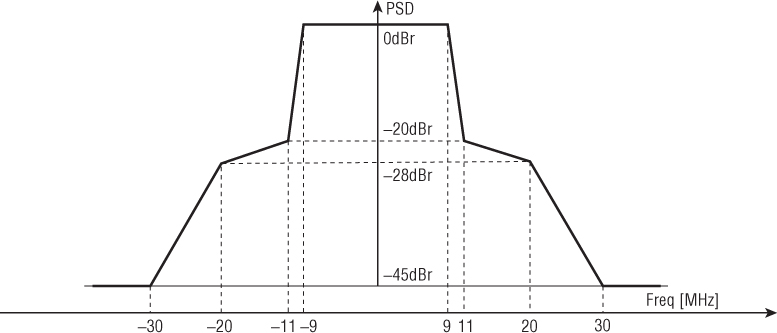
OFDM functions in either the 2.4 GHz ISM or the 5 GHz UNII bands. The channel width is smaller than DSSS or HR/DSSS. The width of an OFDM channel is only 20 MHz compared to 22 MHz for DSSS. Figure 5.11 shows a representation of a 20 MHz–wide OFDM channel.
Figure 5.11 OFDM transmit spectral mask for 20 MHz transmission
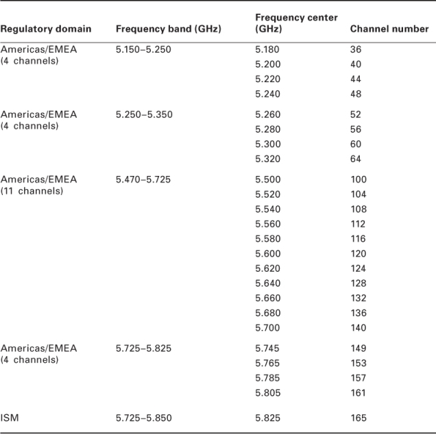
Like DSSS, when OFDM is used in the 2.4 GHz ISM band there are only three nonoverlapping adjacent channels for use. This will limit the use of bonded channels (20/40 MHz wide channels) in IEEE 802.11n (HT-OFDM) deployments that are located in the same radio frequency physical area. In the 5 GHz Unlicensed National Information Infrastructure (UNII) bands, the channel spacing is such that there is no overlap. The frequency range used will determine how many nonoverlapping channels are available for use. In the lower and upper UNII bands, 4 non-overlapping channels are available. The middle UNII band has 15 nonoverlapping channels available. All UNII band channels are 20 MHz wide and separated by 20 MHz from the center frequencies of each channel. Certain regulatory domains, including the United States Federal Communication Commission (FCC) and the European Telecommunications Standards Institute (ETSI), require the use of dynamic frequency selection (DFS) support for wireless devices such as access points that operate in the middle 5 GHz (5.250 GHz–5.725 GHz) UNII band. DFS will allow an access point to change the radio frequency channel it is operating on in order to avoid interfering with certain type of radar systems. Table 5.2 shows the 23 available channels, center frequency, and channel number in the 5 GHz UNII band. Also displayed is a single 5 GHz ISM channel that is available by some regulatory agencies for use with wireless networking.
Table 5.2 5 GHz UNII Band Channels
![]()
IEEE 802.11n Multiple Input/Multiple Output Technology
Multiple input/multiple output (MIMO) is a technology used by IEEE 802.11n devices. MIMO technology potentially has data rates up to 600 Mbps. Currently, devices using MIMO technology are capable of data rates of up to 300–450 Mbps. MIMO provides users with a better overall experience for data, voice, and video communications with throughput up to five times more than current 802.11 a/g, single input/single output (SISO) networks.
SISO is the most basic wireless antenna technology used in a wireless LAN system. One antenna is used at the transmitter to transmit data, and one antenna is used at the receiver to receive the data. Some SISO systems support a technology known as diversity, which uses two antennas with a single radio. Diversity technology will help to lessen the effects of multipath, which is caused by reflections. Diversity and multipath are discussed in more detail in Chapter 7, “WLAN Antennas and Accessories.” Coverage is more predictable and consistent with MIMO networks because devices using this technology are able to utilize reflected signals, which are a problem for wireless networks using other WLAN technologies.
MIMO also allows 802.11n networks better throughput than DSSS or OFDM-based networks at the same distance. IEEE 802.11n MIMO-based networks offer backward compatibility with 802.11a/b/g networks and devices in both the 2.4 GHz ISM and the 5 GHz UNII bands, allowing for deployments to continue using their existing hardware.
Some of the benefits of 802.11n MIMO networks include throughput, reliability, and predictability:
- Five times more throughput
- Enhanced file transfer and download speeds for large files
- Twice as reliable
- Lower latency for mobile communications
- Twice as predictable
- More consistent coverage and throughput for mobile applications
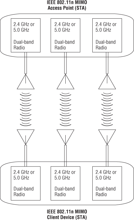
Unlike IEEE 802.11b (HR/DSSS) and IEEE 802.11a/g (OFDM) access points, MIMO access points use multiple radios with multiple antennas. The multiple radio chains and some additional intelligence are what give 802.11n MIMO access points the capability to process reflected signals. Since MIMO works with both the 2.4 GHz ISM and the 5 GHZ UNII bands, a dual-band IEEE 802.11n MIMO access point will have up to six radio chains—three for 2.4 GHz and three for 5 GHz—and six antennas (one for each radio) for data rates of up to 450 Mbps. Figure 5.12 shows that MIMO uses multiple radio chains and multiple antennas to transmit and receive data.
802.11n systems use MIMO technology; they have more receivers and are much more sensitive than the average 802.11a or 802.11g radio. The following techniques are what allow for better performance and much higher data rates (currently up to 450 Mbps with 3 × 3 × 3 MIMO and eventually up to 600 Mbps with 4 × 4 × 4 MIMO):
- Maximal ratio combining (MRC)
- Transmit beam forming (sometimes abbreviated TxBF)
- Spatial multiplexing (sometimes abbreviated SM)
Figure 5.12 MIMO hardware uses separate radio chains for each band and one antenna for each radio.
802.11a/b/g networks are known as single input/single output (SISO) systems, which means that performance can degrade as a result of multipath, poor reception because of obstacles, and RF interference sources. 802.11n MIMO networks can take advantage of multipath to help increase throughput at a given range, providing much higher throughput at the same range.
MIMO Channels
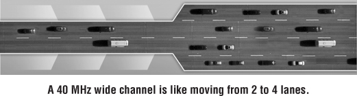
As mentioned earlier in this chapter, IEEE 802.11n MIMO networks can operate in both the 2.4 GHz ISM and 5 GHz UNII bands and are capable of either 20 or 20/40 MHz–wide channels. Even while operating in 20/40 MHz channel width mode, many frames are still transmitted with a 20 MHz channel width. The 20 and 20/40 MHz channel widths are defined by the IEEE for transmission of OFDM modulated data. As you would expect, wider channels mean more data can be transmitted over the RF medium simultaneously. Therefore, wider channels allow higher data throughput. Think of this like cars traveling on a two-lane or a four-lane highway. A 20 MHz–wide channel can be looked at as the two-lane highway and a 40 MHz wide channel the four-lane highway. More cars can pass through four lanes in the same amount of time than can pass through two lanes. Figure 5.13 illustrates this point.
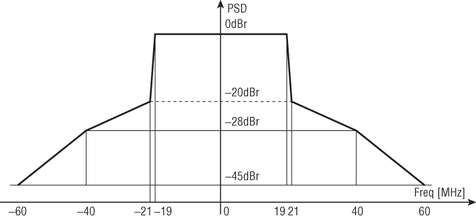
The 20 MHz or 20/40 MHz channels can be used in either the 2.4 GHz or 5 GHz frequency ranges. Because of the limited amount of frequency space in the 2.4 GHz ISM band, there is only one 20/40 MHz–wide channel without any adjacent-channel overlap. Figure 5.14 shows a 40 MHz wide channel as specified in the 802.11n amendment.
![]()
Figure 5.14 OFDM transmit spectral mask for 40 MHz transmission
Co-location of IEEE 802.11b HR/DSSS and IEEE 802.11a/g/n OFDM Systems
Now we will look at the co-location of different 802.11a/b/g/n devices. One thing to understand is that some consider 802.11b systems to be legacy devices that are on the verge of becoming obsolete. However, this may not be the case in all installations. Mostly because of legacy hardware and depending on the type of WLAN installation (typically public guest networks and the retail environment), support for 802.11b networks may still be required. Additionally, the latest revision of the 802.11 standard (IEEE 802.11-2012) still addresses this technology, and therefore it is important to understand the implications of co-location of 802.11b devices.
All IEEE-based wireless LANs can be co-located—that is, they can function in the same RF space. The technologies that the devices use determine how well they work together. Both HR/DSSS (802.11b) and ERP-OFDM (802.11g/n) networks operate in the 2.4 GHz frequency range ISM band. 802.11g-compliant devices are backward-compatible with 802.11b-compliant devices. However, this backward compatibility comes at a price: reduced data throughput. Because of protection mechanisms, ERP-OFDM devices used in 802.11g will suffer in performance when an HR/DSSS device is in the same radio or hearing range of the ERP-OFDM device.
HR/DSSS and ERP-OFDM systems have many common features:
- Both operate in the 2.4 GHz ISM band.
- Both have three nonoverlapping channels.
- Both are subject to interference from other devices operating in the same frequency range.
HR/DSSS and ERP-OFDM (802.11b-compliant and 802.11g-compliant) devices are backward-compatible. ERP-OFDM is rated at 6, 9, 12, 18, 24, 36, 48, and 54 Mbps. Actual throughput in an environment relatively free of interference will be about 15 to 20 Mbps. If a DSSS or HR/DSSS device is introduced in the radio range of the ERP-OFDM device, the throughput will decrease significantly because of protection mechanisms. How much of an impact this makes depends on many factors in the environment. Typically, the decrease in throughput is about 25 percent to 30 percent. It is important to understand that this is not just limited to a single wireless access point or the basic service area. If an 802.11g access point can “hear” another 802.11g access point on the same radio frequency channel that is in ERP protection mode, that access point will also enter a protection mode state. This is known as what some call the “ripple effect.”
Just as co-location of 802.11b/g/n EPR-OFDM systems needs to be taken into consideration, the same holds true with 802.11a/n OFDM systems. The real difference is the frequency band that 802.11a/n systems operate in. As mentioned earlier in this chapter, 802.11 devices operate in the 5 GHz UNII band. The IEEE 802.11n High Throughput (HT) amendment to the standard addresses different protection mechanisms. This is because 802.11n devices can operate in both the 2.4 GHz ISM and 5 GHZ UNII bands. Therefore, an 802.11n access point will need to allow 802.11a devices to utilize the network along with 802.11n devices, both types in the 5 GHz UNII band.
802.11a OFDM and 802.11n HT-OFDM systems have several common features:
- Both operate in the 5 GHz UNII band.
- Both have up to 23 nonoverlapping channels (depending on the regulatory agency).
- Both are subject to interference from other devices operating in the same frequency range.
802.11n HT networks offer various protection mechanisms to ensure interoperability and co-location.
OFDM and HT-OFDM (802.11n-compliant and 802.11a-compliant) devices are backward-compatible. OFDM is rated at 6, 9, 12, 18, 24, 36, 48, and 54 Mbps. Actual throughput in an environment relatively free of interference may be a little higher than an 802.11g environment, about 18 to 22 Mbps. Networks that operate in the 5 GHz UNII band are not subject to co-location issues with DSSS or HR/DSSS, because they operate in different frequency ranges. The 802.11n amendment introduced a new concept called the modulation and coding scheme (MCS). This is a different way to represent the data rates that are available with 802.11n technology. Previously, the IEEE 802.11 standard and amendments specified data rates as individual values—1 Mbps, 2 Mbps, 5.5 Mbps, and 11 Mbps in IEEE 802.11b technology, for example. The IEEE 802.11n amendment to the standard now refers to this as the modulation and coding scheme (MCS). This is because depending on the technology enabled or used, a single MCS may support multiple data rates. For example an MCS Index 7 will support either 65.0 Mbps or 72.2 Mbps, depending on whether short guard interval is enabled.
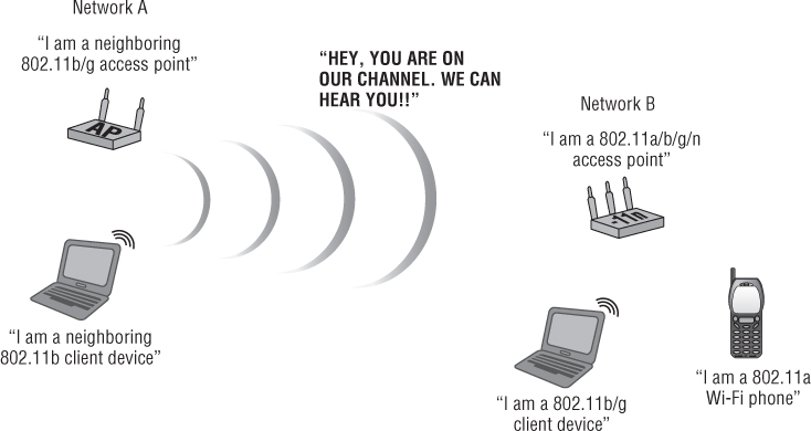
As mentioned earlier in this chapter, 802.11n devices have a maximum data rate or MCS of up to 600 Mbps. However, most technologies available at the time of this writing offer maximum data rates of 300–450 Mbps. Just as devices that operate in the 2.4 GHz ISM band must be able to coexist, devices that operate in the 5 GHz band must be able to coexist as well. Co-location of 802.11a/n devices is possible through the use of additional protection mechanisms. ERP and HT protection mechanisms will be discussed in more detail in Chapter 8. Figure 5.15 illustrates co-location of various 802.11 technologies.
Figure 5.15 Co-location of various IEEE 802.11 devices/technologies
Adjacent-Channel and Co-channel Interference
Adjacent-channel and co-channel interference (two or more RF signals interacting with each other and causing a degradation of performance) is a concern in the design, development, and deployment of IEEE 802.11-based wireless networks. Another term used for this type of interference is “co-channel cooperation.” This is because the wireless devices are contending to use the medium rather than just being seen as radio frequency noise to each other. This type of interference will have an impact on the amount of actual throughput between devices over a wireless network. As mentioned earlier, the 2.4 GHz ISM band has only three nonoverlapping channels. Careful channel planning is required when designing or implementing a wireless network. This type of planning will minimize issues such as poor throughput as a result of adjacent and co-channel interference. Channel planning involves designing wireless networks so that overlapping RF cells are on different (nonoverlapping) channels—for example, channels 1, 6, and 11 in the 2.4 GHz ISM band. This will help optimize performance and minimize degradation of throughput because of adjacent and co-channel interference.
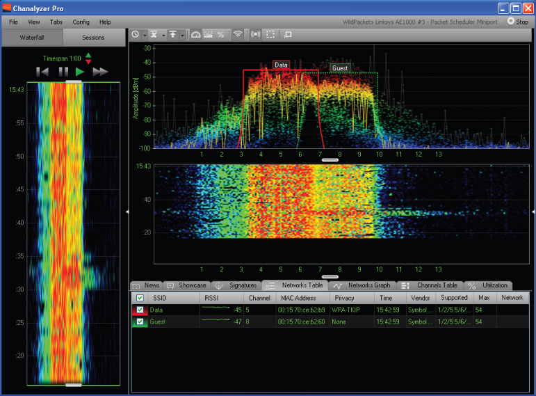
With the advancements in 802.11 technologies, channel planning is more “automated” by the use of spectrum management technology and the IEEE 802.11 standard. However, it is still important to understand the concept of channel planning. RF energy propagates in several directions simultaneously. A well-designed wireless network will account for a three-dimensional propagation. In other words, in a three-story building, the RF from an access point on the second floor building may pass through to the first and third floors; therefore, interference could be an issue if the network is not planned properly. Figure 5.16 illustrates overlapping channel interference with two access points in the 2.4 GHz ISM band.
Figure 5.16 Two access points on overlapping channels as seen in MetaGeeks Chanalyzer Pro. The “Data” access point is on channel 5 and the “Guest” access point is on channel 8 in the 2.4 GHz ISM band.
WLAN/WPAN Coexistence
Wireless personal networks (WPANs) typically consist of portable devices such as personal digital assistants (PDAs), cell phones, headsets, computer keyboards, mice, and now tablet devices. In Chapter 6, we will discuss how the performance of IEEE 802.11 wireless LANs can be affected when co-located with WPAN devices. The IEEE 802.15 standard addresses WPANs and includes Bluetooth and Zigbee networks. Bluetooth is one of the most popular WPAN network technologies and operates in the 2.4 GHz ISM band using frequency hopping spread spectrum (FHSS) technology.
Early Bluetooth devices can cause significant interference while operating in close proximity to IEEE 802.11 wireless LANs. Bluetooth was designed to hop at a rate of 1,600 times per second across the entire 2.4 GHz band, potentially causing significant interference with 802.11 wireless networks. Newer versions of Bluetooth use adaptive frequency hopping (AFH) and thus are less likely to interfere with IEEE 802.11 wireless networks, even though they still operate in the 2.4 GHz ISM band. Devices that use adaptive frequency hopping will try to avoid using the same frequencies, decreasing the chance of interference. Since these devices operate at low power, most WPANs communicate in small, close-range, peer-to-peer networks.
![]()
- Are any devices limited to 802.11b/g/n capability only?
- Does the network require backward compatibility to 802.11b/g/n?
- Does the network need to support guest access?
- What impact would a network using only 5 GHz 802.11a/n have on the business?
- Is it possible to utilize both frequency bands in this deployment to maximize throughput while limiting interference?
Summary
In this chapter, we looked at access methods used to get data from one device to another when multiple users share the medium. These access methods consist of collision avoidance and collision detection:
- CSMA/CD—Carrier Sense Multiple Access/Collision Detection
- CSMA/CA—Carrier Sense Multiple Access/Collision Avoidance
WLANs have no way of detecting collisions; therefore they must use collision avoidance or CSMA/CA. Wireless LANs use half-duplex communication, which decreases the performance of the communication data transfer.
This chapter also looked at the spread-spectrum and physical layer (PHY) technologies used with WLANs and the differences among them. The IEEE standard and various amendments use different spread-spectrum and PHY technologies and unlicensed radio spectrum allowing for data rates up to 450 Mbps. These physical layer (PHY) technologies include:
- FHSS—For data rates of 1 and 2 Mbps
- DSSS—For data rates of 1 and 2 Mbps
- HR/DSSS—For data rates of 5.5 and 11 Mbps
- OFDM—For data rates up to 54 Mbps
- HT-OFDM—Currently for data rates of up to 450 Mbps, eventually may be up to 600 Mbps
Even though FHSS is considered legacy technology for WLANs, it is still important to understand some of the basics of this technology since it is still in use today in many industries in various types of wireless technologies, including IEEE 802.15 personal area networking (PAN), Bluetooth, and cordless telephones.
We looked at the different channel sets used with 802.11 wireless networks and some of the co-location considerations.
Some of the physical layer technologies discussed in this chapter are more susceptible to interference than others. This can make installations in some industries challenging. We also looked at co-location of HR/DSSS and ERP-OFDM systems and some of the challenges it can pose. Finally, this chapter discussed the coexistence of WPANs and WLANs and the various devices and technology that can cause interference when working in the same RF space.
Exam Essentials
Review Questions
1. IEEE 802.11a/b/g/n devices use what type of communication?
A. Half diplex
B. Full diplex
C. Half duplex
D. Full duplex
2. HR/DSSS devices operate in which frequency range?
A. 2.400 GHz ISM
B. 5.250 GHz UNII
C. 5.350 GHz UNII
D. 5.750 GHz UNII
E. 5.725 GHz ISM
3. How many access points can be co-located without channel reuse in the same radio frequency area to maximize total system throughput while minimizing RF interference in an IEEE 802.11g network?
A. Two
B. Three
C. Four
D. Six
4. Devices compliant with which amendment to the IEEE standard use multiple radio chains and multiple antennas?
A. 802.11a
B. 802.11b
C. 802.11g
D. 802.11n
5. What technology is used to send WLAN data over a wireless medium using many subcarrier frequencies?
A. Wireless broadband
B. Narrowband
C. Spread-spectrum
D. Spectral masking
E. Wideband
6. Which two channels could be used so that the access points do not interfere with each other in an 802.11b wireless network? (Choose three.)
A. Channel 1 and channel 5
B. Channel 3 and channel 9
C. Channel 6 and channel 11
D. Channel 2 and channel 8
E. Channel 4 and channel 7
7. Which network access method attempts to avoid collisions?
A. CSMA/CA
B. CSMA/CD
C. CSMA/CR
D. CSMA/DSSS
8. DSSS uses which spreading code at 1 Mbps?
A. Barker
B. CCK
C. DBPSK
D. DQPSK
9. FM radio stations use what type of RF communication?
A. High power, narrow bandwidth
B. High power, wide bandwidth
C. Low power, narrow bandwidth
D. Low power, wide bandwidth
10. An HR/DSSS channel is how wide?
A. 1 MHz
B. 20 MHz
C. 22 MHz
D. 40 MHz
11. Bluetooth devices use _____, which can potentially cause interference with WLANs.
A. Bluetooth spread spectrum (BTSS)
B. Orthogonal frequency division multiplexing (OFDM)
C. Direct-sequence spread spectrum (DSSS)
D. Frequency hopping spread spectrum (FHSS)
12. OFDM that is used with 802.11a and 802.11g stations (STA) supports a maximum data rate of Mbps.
A. 11
B. 22
C. 33
D. 54
13. Which wireless LAN technology can be used to obtain the highest data transfer rate possible?
A. DSSS
B. Ethernet
C. HT-OFDM
D. OFDM
14. Which frequency ranges are used in an IEEE 802.11a-compliant wireless LAN? (Choose two.)
A. 900 MHz ISM range
B. 2.40 GHz ISM range
C. 5.25 GHz UNII range
D. 5.35 GHz UNII range
15. Stations (STA) operating in which two IEEE 802.11 amendments are interoperable?
A. 802.11 and 802.11a
B. 802.11a and 802.11b
C. 802.11a and 802.11g
D. 802.11b and 802.11g
16. Without any regulatory domain taken into consideration, the 2.4 GHz frequency range allows for how many channels using 802.11b?
A. 3
B. 6
C. 11
D. 14
17. FHSS uses which communication method to exchange data?
A. 1 MHz–wide subcarriers
B. 20 MHz–wide subcarriers
C. 22 MHz–wide subcarriers
D. 40 MHz–wide subcarriers
18. What is the maximum data rate of HR/DSSS 802.11b devices?
A. 5.5 Mbps
B. 11 Mbps
C. 24 Mbps
D. 54 Mbps
19. What IEEE 802.11 PHY technology specifies that frequencies change regularly while transmitting and receiving data?
A. DSSS
B. OFDM
C. FHSS
D. ERP-OFDM
20. Which wireless LAN technology in wireless networking uses the effects of multipath to provide data rates of 600 Mbps?
A. OFDM
B. HR/DSSS
C. HT/DSSS
D. MIMO