
Chapter 11
Performing an RF Wireless LAN Site Survey
The following CWTS exam objectives are covered in this chapter:
- 4.2 Define and differentiate between the following WLAN system architectures and understand site survey concepts related to each architecture. Identify and explain best practices for access point placement and density.
- Multiple channel architecture (MCA)
- Single channel architecture (SCA)
- 4.3 Describe the primary purpose and methodology of manual and predictive site surveys
- 4.4 Define the need for and the use of a manual site survey tool and differentiate between the following manual site survey types
- Active surveys
- Passive surveys
- 4.5 Differentiate between manual and predictive site surveys
- Advantages and disadvantages of each site survey methodology
- 4.6 Define the need for and use of site survey software or a protocol analyzer in a manual site survey as it relates to identifying, locating, and assessing nearby WLANs
- 4.7 Differentiate between site survey methods for indoor and outdoor wireless service
- 4.8 Define the need for and use of a spectrum analyzer in a site survey
- Identification and location of interference sources
- Differentiation of Wi-Fi and non-Wi-Fi interference sources
- 4.9 Understand industry best practices for optimal use of directional and omni-directional antennas in site surveys
This is the second of two chapters on the subject of wireless LAN site surveys.
In Chapter 10, “Wireless LAN Site Survey Basics,” you learned about the business aspects of a site survey, which included gathering of information such as the business requirements for the wireless network, interviewing managers and users, and gathering site-specific documentation. It is important to have all the necessary groundwork prior to starting a physical wireless RF site survey. Having all the correct information in hand will allow for a complete and thorough survey, which in turn will result in a successful wireless LAN deployment.
In this chapter, you will see some of the components of performing an RF wireless LAN site survey, including determining areas of RF interference by using a spectrum analyzer. Taking into consideration both Wi-Fi and non-Wi-Fi interference sources and understanding how this interference will affect the deployment are also important parts of performing a site survey. We will also look at different types of site surveys, both manual and predictive modeling. We will discuss the two types of manual site surveys, passive and active, and show the advantages and disadvantages of both. Understanding the steps involved and the details of each site survey type will help a wireless LAN engineer determine the best methodology to use. You will learn about some of the tools that may be used in a site survey, including wireless protocol analyzers and wireless scanners. Finally, we will look at the two different types of channel architecture and best practices for hardware placement, including access points and antennas, as well as some of the limitations you may encounter during the physical site survey process.
The Physical Radio Frequency Site Survey Process
After all the up-front work is completed, such as gathering of information, including the business requirements and site-specific documentation, defining physical and data security requirements, and interviewing managers and users, it is time to start the physical RF site survey process and the wireless LAN design. This is one of the most important parts of a successful wireless LAN deployment. This process includes locating areas and sources of RF interference as well as RF coverage (or lack thereof), and determining the locations of access points, bridges, sensors, and other infrastructure devices that will be used with the wireless network. The following sections detail the entire physical wireless site survey process and guidelines. The RF physical site survey is a very subjective topic and people have different opinions on how the entire process works. In many cases, this process can be tailored based on the individual needs or requirements of the location where the wireless LAN will be installed. The following steps should be viewed as recommendations or guidelines:
In today's wireless LAN world, an RF site survey can be considered an ongoing process. Just a few years ago, not nearly as many wireless networks existed as do today, so the interference factor was not as significant. With the RF dynamics constantly changing and more devices using RF for communications, it is up to the network engineer to take into consideration that site requirements may also be constantly changing. Therefore, the RF site survey may need to be updated periodically.
Radio Frequency Spectrum Analysis
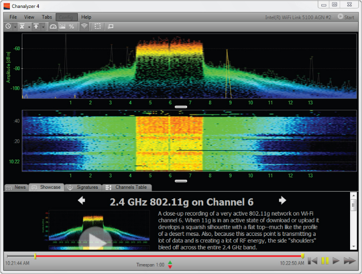
The wireless LAN site survey includes finding areas of RF coverage and RF interference as well as locations for hardware, such as access points, bridges, and other infrastructure devices. Although radio frequency is not visible to the human eye, some tools are available to “see” a visual representation of the RF. A common tool is the RF spectrum analyzer. Figure 11.1 shows a spectrum analyzer view of the 2.4 GHz ISM band with the access point set to channel 1. Spectrum analyzers will vary in cost and complexity depending on the frequency ranges they are designed to work with.
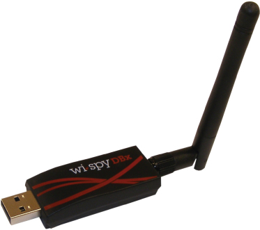
Some spectrum analyzers are available that are designed specifically for the wireless LAN market. These usually work only in the license-free radio bands and are typically less expensive because of spectrum limitations. Spectrum analyzers allow you to view the physical layer of communication between devices used in wireless networking. Wireless LAN spectrum analyzers are available in PC card models, devices that attach to a USB port on the computer, and instrumentation-style devices that can be used for applications other than wireless networking. Figure 11.2 shows an example of a WLAN spectrum analyzer that connects to a USB port on a computer.
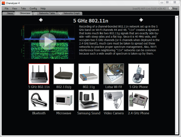
Figure 11.1 Chanalyzer Pro shows RF capture of an IEEE 802.11b/g access point on channel 1.
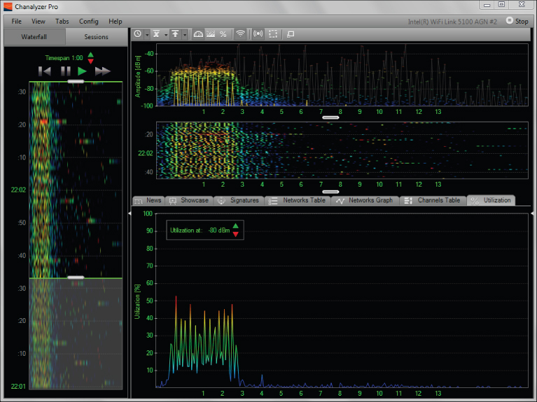
Figure 11.2 MetaGeek DBx spectrum analyzer for IEEE 802.11a/b/g/n networks operating in the 2.4 GHz and 5 GHz frequency ranges
Some manufacturers of wireless LAN equipment integrate spectrum analyzer tools into devices such as wireless LAN access points or wireless LAN controllers for constant monitoring of the radio frequency. Others offer standalone products that can be used to monitor more specific areas. Listed here are some manufacturers of wireless LAN spectrum analyzers:
| Product | Website |
| AirMagnet Spectrum XT | www.flukenetworks.com |
| BumbleBee Handheld | www.bvsystems.com |
| Motorola AirDefense | www.airdefense.net |
| Wi-Spy by MetaGeek | www.metageek.net |
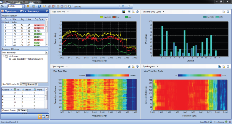
The ability to analyze the RF allows a site surveyor to find areas that lack coverage, also known as dead spots, as well as interference caused by other devices and other IEEE 802.11 wireless networks that operate in the same radio frequency range. Although a spectrum analysis is not a requirement for a wireless LAN site survey, it is beneficial in most medium- to large-scale deployments of wireless networks. Because of the vast number of devices that use unlicensed radio bands, spectrum analysis can be considered an ongoing process. Performing regular spectrum analysis gives wireless LAN engineers the capability to monitor the area in which wireless LAN devices are located for RF interference and other issues. Figure 11.3 shows an example of a USB-based spectrum analyzer designed for IEEE 802.11 wireless networks.
Figure 11.3 AirMagnet SpectrumXT USB Spectrum Analyzer
Wi-Fi and Non-Wi-Fi Interference Sources
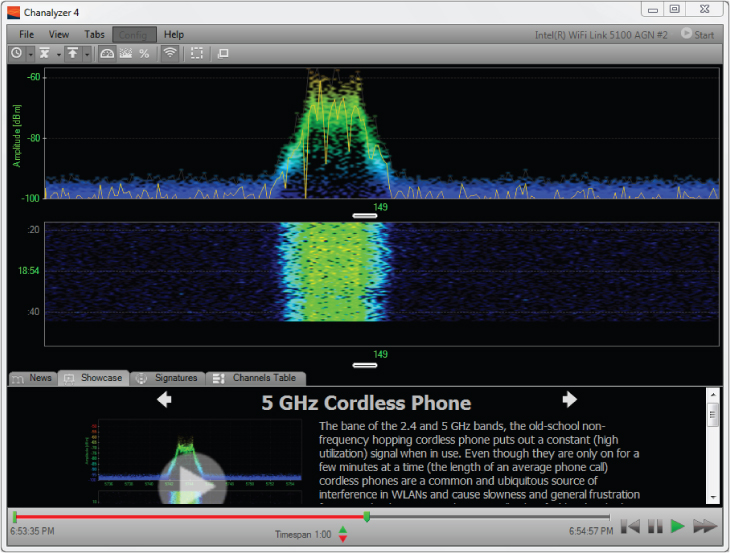
The performance of a wireless network can be significantly affected by various types of interference sources. Interference may be either intentional or unintentional and caused both by IEEE 802.11 wireless networks and by other devices that also operate in the 2.4 GHz ISM or 5 GHz UNII band. The use of portable and mobile devices that employ radio frequency for communication continues to rise, so interference from these devices is also more prevalent. As mentioned in previous chapters of this book, these interfering devices typically operate in the unlicensed radio spectrum 2.4 GHz ISM band. Other sources of interference from the industrial, medical, and scientific communities will also affect the amount of interference. Non-Wi-Fi interference in the ISM band can be caused by devices such as these:
- Microwave ovens
- Cordless telephones
- IEEE 802.15 Bluetooth devices
- Medical equipment
- Manufacturing or industrial equipment
- Wireless video cameras
- Radar systems (5 GHz bands)
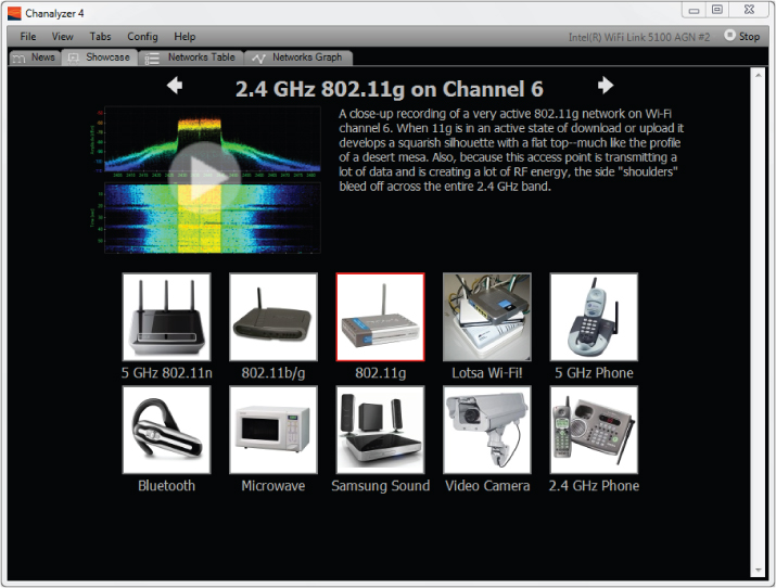
Figure 11.4 Microwave oven operating at maximum power for 30 seconds and IEEE 802.11b/g access point on channel 1
This is by no means a complete list, but it does contain some of the devices used daily that may cause some level of interference in the world of wireless networking. Figure 11.4 shows an example of interference caused by a microwave oven. This figure shows a spectrum analyzer capture that ran for approximately 30 seconds. Microwave ovens operate in the 2.4 GHz frequency range and, depending on the unit, may cause interference with IEEE 802.11 wireless networks.
In Exercise 11.1, you will use the Chanalyzer spectrum analysis software from MetaGeek to look at some sample radio frequency captures.
Wi-Fi Interference
Wi-Fi interference is caused by IEEE 802.11 wireless LAN devices that operate in the 2.4 GHz ISM or 5 GHz UNII band. In some cases, this is the largest source of interference for wireless LANs. There are two types of Wi-Fi interference: co-channel interference (other devices on the same channel) and adjacent channel interference (other devices on overlapping channels). See the sidebar “Standards vs. Industry Definitions” for more about how these terms are distinguished in the industry generally and by the CWNP exam.
The following network types will cause Wi-Fi interference:
- FHSS networks: 2.4 GHz (Legacy)
- DSSS networks: 2.4 GHz
- ERP-OFDM networks: 2.4 GHz
- OFDM: 5 GHz
- HT-OFDM: 2.4 GHz and 5 GHz (802.11n)
Wi-Fi devices that cause interference can be operating in either infrastructure mode or ad hoc mode. The number of devices that are part of the wireless network will also determine the extent of the interference. In Chapter 5, “Physical Layer Access Methods and Spread-Spectrum Technology,” we discussed different types of spread-spectrum technologies that wireless networks use to communicate. FHSS, DSSS, ERP-OFDM, OFDM, and HT-OFDM are technologies used for IEEE 802.11 wireless networking in the 2.4 GHz and 5 GHz bands. However, some of these technologies are used in non–wireless LAN devices as well. For example, Bluetooth devices operating in the 2.4 GHz ISM band also use FHSS technology for communication. Zigbee devices operate in the 2.4 GHz band and use DSSS technology for communication. Depending on the manufacturer, 2.4 GHz cordless phones may use either FHSS or DSSS. Performing an RF spectrum analysis is one way you can determine the source of this type of interference. If an instrumentation spectrum analyzer (a calibrated device that has the capability to view entire radio spectrums) is used, it will be necessary to understand how to interpret the data collected as well as how to operate the device.
![]()
Performing a Manual Radio Frequency Wireless LAN Site Survey
Although some in the industry consider the manual wireless LAN RF site survey process “old school,” it provides some of the most accurate results. A manual site survey requires a physical walkthrough of the area, recording information to determine the performance of clients and devices that will be connected to the wireless network. This type of site survey can be very accurate because the surveyor is recording actual statistics, such as:
- Signal strength
- Signal-to-noise ratio (SNR)
- Data rate of connected devices
- Radio Frequency interference
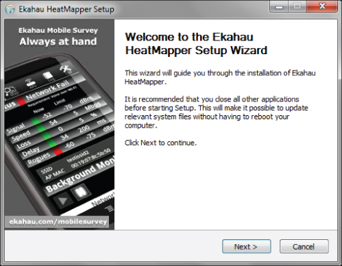
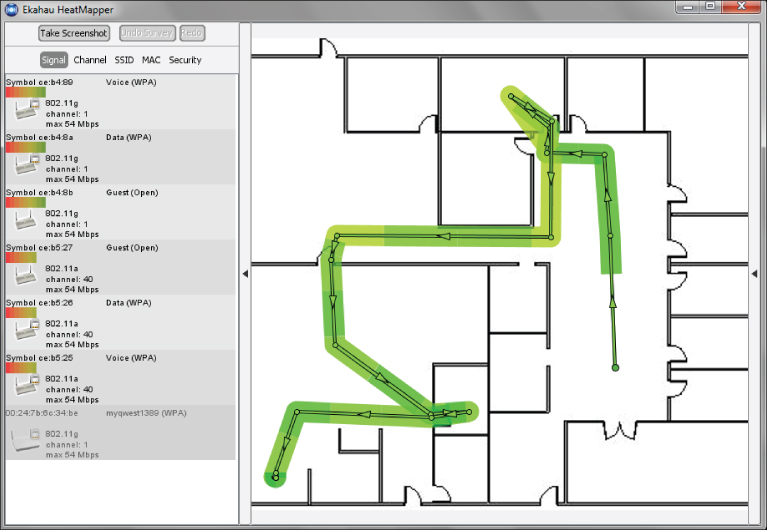
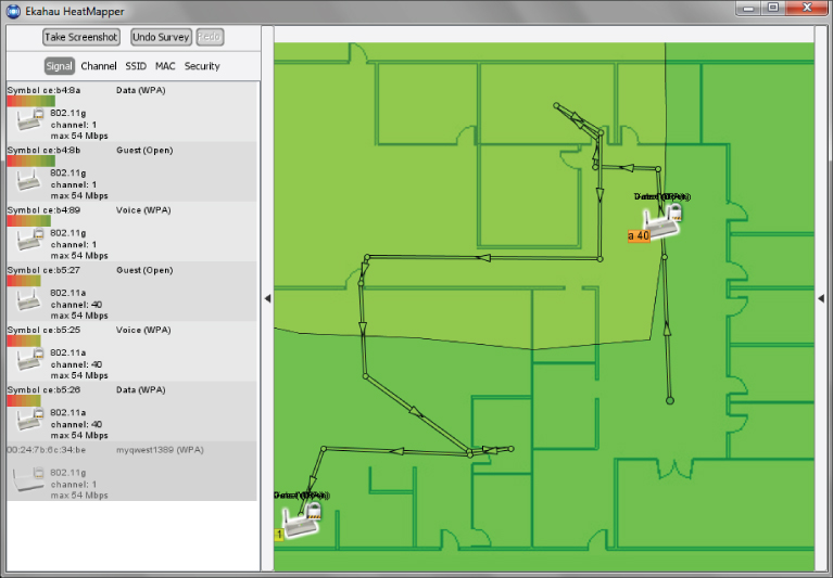
These measurements are recorded while physically moving through the facility or location. Recommended received signal strength and signal-to-noise ratio (SNR) values are discussed later in this chapter. Small-scale manual site surveys can be performed inexpensively by using either a wireless client adapter with site survey functionality, one of several freeware/shareware utilities, or commercial software designed specifically for this type of application. Figure 11.5 shows an example of a free site survey software program.
Figure 11.5 Ekahau HeatMapper – Wi-Fi Coverage Mapping Site Survey Software Utility is a free download from Ekahau.

The manual site survey process can be used for recording measurements to determine the actual placement of hardware infrastructure devices and for spot checking, locating other IEEE 802.11 wireless networks, or verification after a predictive site survey has determined the placement of these devices. Not too long ago this manual process was the only way to perform a wireless LAN site survey. The main advantage of the manual process is accuracy. One disadvantage is that it can be very time-consuming depending on the extent of the installation. Some of the basic steps include:
Obtaining a Floor Plan or Blueprint
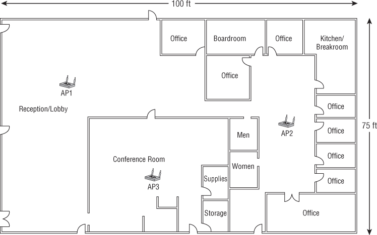
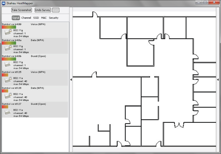
The first step in a manual site survey is to review a floor plan or blueprint of the location. Many in the industry refer to a floor plan as a “map.” This could be a simple sketch and is required to note access point placement as well as readings. The readings to note on the floor plan include signal strength and signal-to-noise ratio values from client devices. Figure 11.6 shows a basic floor plan of a small office building. The floor plan should be marked with approximate access point locations. In some cases, a floor plan or CAD drawing of the location may not be available. Depending on the size of the location, a fire evacuation plan could be photographed or scanned in and used as a starting point to create a drawing and may be adequate for the site survey.
Figure 11.6 Approximate access point locations
![]()
Identifying Existing Wireless Networks
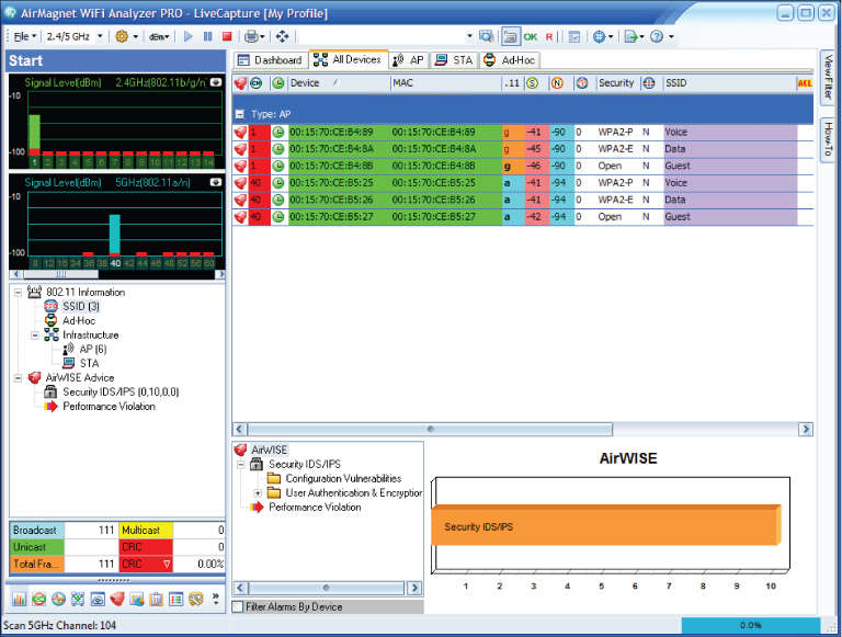
As part of a manual site survey, you should identify existing wireless LANs in the area, noting locations that include possible sources of radio frequency interference and may have an impact on the wireless LAN that will be installed. Using a device or software program designed specifically for wireless networks would be ideal. However, freeware or shareware programs may be satisfactory. Figure 11.7 shows an example of a software program that can be used to find existing IEEE 802.11 wireless networks.
Figure 11.7 The AirMagnet Wi-Fi Analyzer can be used to view existing IEEE 802.11 wireless networks.
Testing Access Point Placement
Once you have identified potential locations for access points, you can start testing the proposed access point placement. This can be done by temporarily mounting an access point at the desired location to get the most accurate results. In some cases, a tool or fixture made specifically for wireless LAN site surveys or even a tall ladder could be used as a temporary mounting solution. Refer to the documentation that was created prior to going on-site for mounting locations.
It is always best to use test access points from the same manufacturer and, if possible, the same model that will be used in the actual deployment during the pre and post deployment manual site survey process. This practice will yield a better outcome than using generic access points during testing. Figure 11.8 shows an example of a temporary mounting solution.
Figure 11.8 Access point temporarily mounted using an expandable light pole

Using one or possibly two temporarily mounted access points, document the results of the testing while moving around the facility. One testing method is to IEEE 802.11 authenticate and associate to the test access points using the site survey computer. A passive process (listening to all access points in the area) may also be used for this type of site survey. The area to be tested should include a reasonable proximity around the temporarily mounted access point. The extents should be the desired minimum received signal threshold, –67 dBm for example. The information recorded and documented will depend on the surveyor but commonly includes signal strength and signal-to-noise ratio. It may be necessary to make adjustments of access point mounting during the testing process, based on the results of the onsite testing process. It would be beneficial to test an actual wireless client device and software application that will be used with the network in order to see if the performance meets expectations. Software-assisted programs as described later in this chapter are commonly used for a site survey of any size in today's wireless LAN deployments.
Analyzing the Results
Once all the testing is complete, it is necessary to perform an offline analysis to determine the final placement of access points or other infrastructure devices that may be used in the wireless LAN deployment. This may include making adjustments from the original plan prior to testing or possibly adding and removing access points. The use of various antennas may also need to be analyzed and documented.
Advantages and Disadvantages of Manual Site Surveys
Listed here are some of the advantages and disadvantages of the manual site survey process:
- Advantages
- Very accurate because it is based on actual readings
- Physical characteristics of building are physically tested (attenuation values)
- Allows verification of actual RF signal coverage
- Allows marking exact installation locations of hardware while on-site
- Disadvantages
- Can be very-time consuming
- Usually only one access point is used for testing, so readings will need to be merged
- Requires a physical walkthrough of entire location
- Many areas require an escort and special clearances for access

Software-Assisted Manual Site Survey
The manual site survey technique discussed earlier in this section may be adequate for smaller deployments or for organizations that have limited resources and budget. Manual site surveys can also be accomplished with the aid of commercial software programs designed specifically for this process. These programs vary in cost, complexity, and features and contain many advanced features, including:
- Capability to perform both passive and active surveys
- Capability to import floor plans with support for many graphic formats, including JPG, BMP, and CAD formats
- Capability to record critical data such as signal and signal-to-noise ratio
- Visual representation of RF signal propagation of surveyed areas
- Postsurvey offline analysis of collected data
The Passive Wireless LAN Site Survey
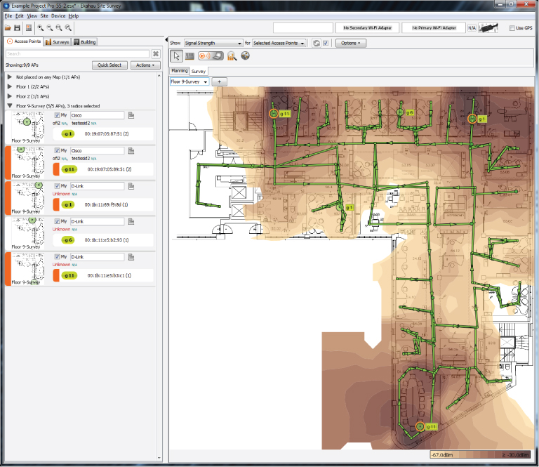
A passive site survey consists of monitoring the air and recording the radio frequency information from all wireless access points and wireless client stations or devices in the “hearing range” of the surveying station and includes radio frequency information from your own and neighboring devices. This type of site survey does not require an IEEE 802.11 authentication and association to an access point, and no traffic is passed between the survey station and the access point. A passive survey will provide an overall snapshot of the RF in use in or around the location, including RF noise and other IEEE 802.11 wireless networks in the area. It is used to get an overall picture of the wireless LAN access points that are transmitting within the area being surveyed. Figure 11.9 shows an example of a commercial site survey application in passive mode.
Figure 11.9 Ekahau Site Survey (ESS) showing passive survey
Since passive site surveys do not require an association to an access point, all radio frequencies will be detected, displayed, and recorded. Most commercial software applications with this functionality will have the capability to filter on specific access points from the information that was recorded.
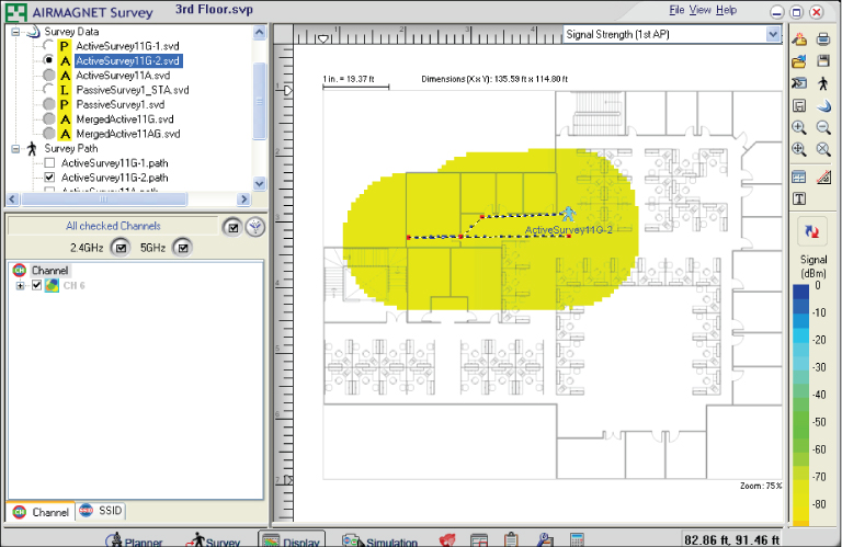
The Active Site Wireless LAN Survey
An active site survey consists of a survey device such as a notebook computer associating to an access point prior to taking readings and collecting the data. Some claim this type of manual survey will provide more accurate results because of this direct IEEE 802.11 authentication and association to an access point. The association of the survey device to an access point will actively send and receive some basic RF information to and from the access point, allowing the information about signal strength and noise levels to be recorded. Figure 11.10 shows a commercial site survey performing an active site survey.
Figure 11.10 AirMagnet Survey showing an active site survey
Performing either a passive or active site survey using software involves many of the same steps discussed in “Performing a Manual Radio Frequency Wireless LAN Site Survey” earlier in this chapter. The main difference is the features and capabilities that are available in these commercial software packages. These elaborate features will eliminate the need to manually document and record all the information obtained while walking the area because the program handles this task for the surveyor.
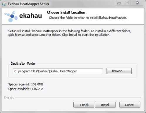
In Exercise 11.2 you will explore the Ekahau HeatMapper site survey program. If you have a floor plan of your area, you can perform an actual manual wireless site survey.
- Wi-Fi coverage mapping tool
- Free of charge
- No official support provided
- Laptop computer running Windows XP, Windows Vista, or Windows 7 (64-bit or 32-bit)
- 512 MB of RAM
- 1 GB hard disk space
- 500 MHz or faster processor
- Wireless network adapter (internal or external)

Manual Site Survey Toolkit
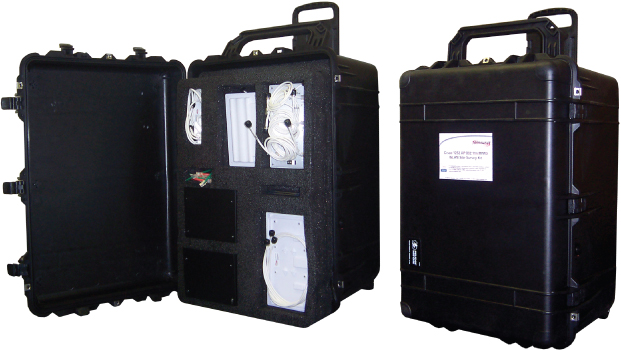
To perform a manual site survey, you need a toolkit containing essential components. A floor plan or blueprint is required to record data collected during a manual site survey. If an assisted software program is used, both an electronic version of the floor plan and a paper printout are necessary. Site survey toolkits will vary in complexity and cost. Planning the equipment and tools you will need for a manual site survey is very important. I recommend you take everything you will need and not take items you will not need. Taking items you do not need creates an unnecessary burden. Many times you may be the only person performing the physical survey, and you need to realize the limits. You can create your own site survey kit based on what you will need, or you can purchase a kit from a manufacturer that is built specifically for this purpose. Figure 11.11 shows a wireless LAN IEEE 802.11n MIMO site survey kit from TerraWave Solutions.
Figure 11.11 802.11n MIMO site survey kit from TerraWave Solutions contained in a durable and airline-approved transportable carrying case Image provided by: WWW.TERRAWAVE.COM.
The following lists some items that may be included in a Wireless LAN site survey kit. Keep in mind this covers some of the most common items and the kit will vary based on the site survey and the person performing the site survey.
Performing a Predictive Modeling Site Survey
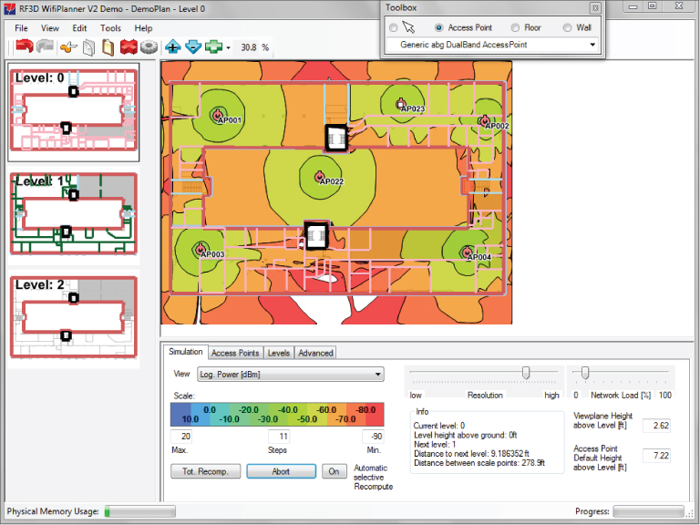
A predictive modeling site survey can be an accurate way to design a wireless LAN without having to spend time on-site performing a physical walkthrough and testing of the entire location. A predictive modeling site survey is a software-based site survey in which a floor plan (map) or drawing of the area to be surveyed is imported into the program. The program then simulates the radio frequency propagation from access points by using the attenuation properties of various structural components. The surveyor can trace over walls, windows, doors, and other elements of the physical location in order to estimate the RF attenuation and show how the RF propagates based on the environment. This type of site survey can be performed in several different ways depending on the equipment used. You can use a standalone commercial software program designed specifically for this purpose or, in some cases, manufacturers build this site survey functionality directly into a wireless LAN controller. Some manufacturers now have web-based wireless site survey programs, and the design is performed online.
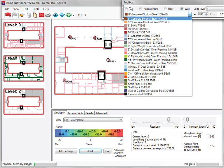
This type of site survey requires the wireless engineer or surveyor to input a floor plan drawing of the facility, such as a CAD, JPEG, BMP, or other format file, directly into the software program or the controller. Then details such as the attenuation values of the facility are added. This information includes:
- Type of walls: for example, drywall, brick, or poured concrete
- Thickness of walls
- Types of windows, including glass, thickness, and coating
- Type of doors, such as hollow core, solid core, fire doors, wood, steel
- Location of certain types of furnishings, such as cubicle offices
- Height of the ceiling
One thing to keep in mind about a predictive modeling site survey is that the accuracy and final results are only as good as the information that was input into the program. Basically it equates to “garbage in, garbage out.” It is essential for the surveyor to use accurate information about the location, including the attenuation value of all the building materials. Figure 11.12 shows a predictive modeling wireless LAN site survey tool.
Here are some the advantages and disadvantages of using the predictive modeling site survey process:
- Advantages
- Limited time on-site
- Does not require a complete physical walkthrough for testing, but a site visit is recommended.
- Allows for easy adjustment of access point locations and settings
- Can model different scenarios
- Disadvantages
- Surveyor may be unfamiliar with the location's physical characteristics
- Accuracy limited to data input within program
- Requires extensive knowledge of physical properties of the installation area including attenuation values
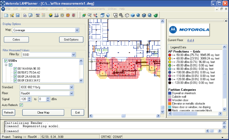
Figure 11.12 Motorola LANPlanner showing a predictive modeling site survey
In Exercise 11.3, you will explore a predictive modeling site survey program.
- Windows 7/Vista
- Windows XP SP2 or
- Windows 2000 SP3
- Internet Explorer 5.01 or later (for online licensing)
- Microsoft .NET Framework 4.0 (free download from Microsoft)
- Processor: Intel Pentium 2.0 GHz or faster
- Display: 1024 × 768 or more
- RAM:
- 1 GB for small and medium plans (<50 APs)
- 2 GB recommended for larger plans

There are many different site survey programs to choose from, both commercial and freeware or shareware. You should compare the programs and determine which would be best suited for your environment based on features, cost, and capabilities. Here are many common standalone programs for predictive modeling or manual site surveys that are available on the market today:
| Site survey software program | Website |
| AirMagnet Survey/Planner | www.airmagnet.com |
| AirTight Networks | www.airtightnetworks.com |
| Berkeley Varitronics Systems (BV Systems) Swarm | www.bvsystems.com |
| Ekahau Site Survey | www.Ekahau.com |
| Fluke Networks InterpretAir | www.flukenetworks.com |
| Motorola LANPlanner | www.motorola.com |
| Motorola SiteScanner | www.motorola.com |
| Psiber RF3D WiFiPlanner | www.psiber.com |
| TamoGraph Site Survey | www.tamos.com |
| VisiWave – AZO Technologies | www.visiwave.com |
| InSSIDer (freeware) | www.metageek.net |
| NetStumbler (donationware) | www.netstumbler.com |
Some enterprise wireless client adapter utilities can also be used in manual RF wireless LAN site surveys to provide basic information such as signal strength and signal-to-noise ratio.
Internet-Based Predictive Modeling Site Survey
Some manufacturers of wireless LAN equipment have Internet or web-based predictive modeling wireless site survey programs available. This type of program is based on the assumption that you will be using their equipment in your wireless LAN deployment. The Aerohive “Wi-Fi Planning” tool is robust and free to access. You can also access free online training on its use. The process in using these tools is fairly straightforward. You need to request access or create an account on their website. You will then be able to log in and upload a floor plan map to the website program.
| Site survey Internet-based | Website |
| Aerohive Wi-Fi Planner | www.aerohive.com/planner |
| Meraki WiFi Mapper | www.meraki.com |
Protocol Analysis
Wireless LAN protocol analyzers are becoming a common tool, and many network administrators will have one as part of their wireless LAN toolkit. A protocol analyzer allows a network administrator or engineer to view all wireless frames that are traversing across the air in the hearing range of the analysis device. At one time protocol analysis was a specialty role, and without extensive training few people had the skills to perform this task. Along with the evolution of wireless LAN technology in recent years, protocol analyzers are becoming more mainstream, affordable, and easier to use. Many variations of analyzers are available in the market today. Listed here are some of the manufacturers and their products:
| Manufacturer | Product | Website |
| AirMagnet | WiFi Analyzer | www.airmagnet.com |
| BV Systems | Yellowjacket | www.bvsystems.com |
| Motorola | AirDefense Mobile | www.airdefense.net |
| MetaGeek | Eye P.A. | www.metageek.net |
| NetScout | Sniffer | www.netscout.com |
| Network Instruments | Observer | www.networkinstruments.com |
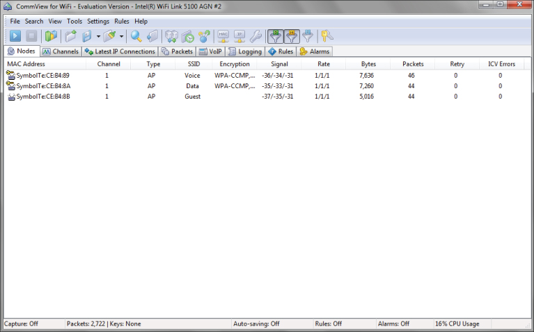
| TamoSoft | CommView for WiFi | www.tamos.com |
| WildPackets | OmniPeek | www.wildpackets.com |
![]()
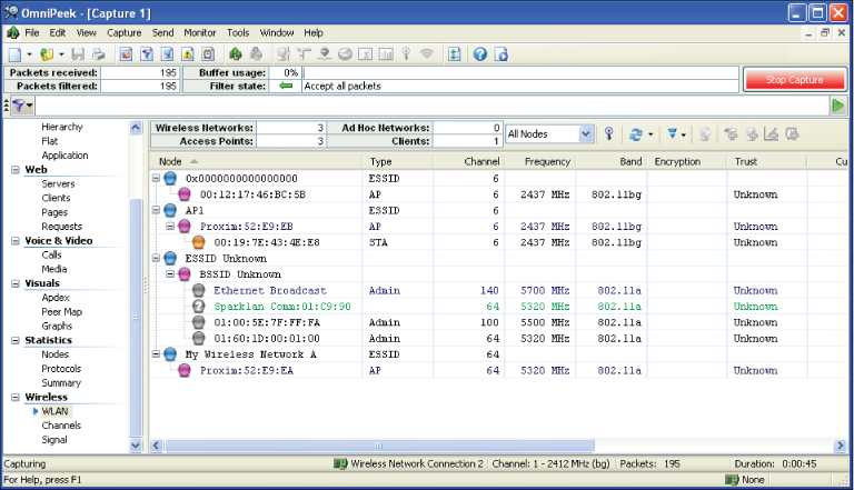
Protocol analyzers are available in software programs that can be installed on a notebook computer and are also available in specialty dedicated handheld devices. In addition to performing protocol analysis or frame decoding, many analyzers are feature-rich, with the capability to view security information, perform legislative compliance analysis and reporting, and generate a variety of reports. Figure 11.13 shows an example of a wireless LAN protocol analyzer.
The main goals of a wireless LAN analyzer, or any protocol analyzer, are to troubleshoot network problems, gather information about security issues, and optimize the network's performance. When it comes to wireless LAN site surveys, a protocol analyzer is a valuable tool for evaluating which wireless LAN devices are currently in the same RF space where the proposed wireless LAN will be deployed. They can also be used to view the signal strength, security implementations, network name or SSID, and which channels access points and other devices are currently operating on. An analyzer will show not only access points but any wireless LAN device that may have an impact on the site survey and deployment. Some of the devices an analyzer is able to locate and identify include:
- Access points
- Ad hoc networks
- Wireless bridges
- Mesh networks
- Client devices
Figure 11.13 OmniPeek by WildPackets identifies nearby wireless networks.
In Exercise 11.4, you will explore a protocol analyzer.
- A compatible wireless adapter. For the up-to-date list, visit www.tamos.com/products/commwifi.
- Pentium 4 or higher.
- Windows XP/2003/Vista/2008/7 (both 32- and 64-bit versions).
- 10 MB of free disk space.


Documenting Existing Network Characteristics
Existing wireless networks can play a big role in a new wireless LAN deployment. Understanding the current location of infrastructure and other wireless LAN devices is an important part of a wireless LAN site survey. One way to see devices that are part of a wireless network is to use a protocol analyzer. Other programs will also be able to view existing wireless networks, such as NetStumbler and InSSIDer, and in some cases these programs may be adequate based on the complexity and size of the site survey. But these typically do not have the extensive feature set that many protocol analyzer packages have.
Some of the questions that you should take into consideration when performing a wireless LAN site survey are:
- What frequency range will the new wireless LAN operate in?
- Are there any existing IEEE 802.11 wireless LANs in the same RF space?
- Will all or part of the existing wireless LAN be utilized in the new deployment?
- What effect will the neighboring wireless networks have on this deployment?
Ignoring existing IEEE 802.11 wireless networks may have a significant impact on how the wireless LAN will operate and result in poor performance for the clients or devices that will be connecting.
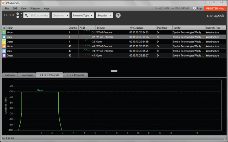
Figure 11.14 shows an example of a software tool that will identify existing wireless networks.
Figure 11.14 InSSIDer by MetaGeek can identify IEEE 802.11 wireless networks.
RF Coverage Requirements
As mentioned previously, one of the main goals of a wireless LAN site survey is to determine areas of RF interference and RF coverage. The details of the required coverage and capacity in any wireless network are part of the wireless LAN design, which involves determining the need, use, and business requirements of the network. This was discussed in Chapter 10. Some of the factors that need to be taken into consideration during a physical site survey are:
- Size of the physical location
- Number of users and wireless devices, including bring your own device (BYOD)
- Obstacles that may impact RF signal propagation
- Radio frequency range
- Bandwidth requirements of applications to be used
- Selected radio frequency of wireless LAN hardware
The planning process will provide some of the answers whereas a site visit and on-site testing will determine others, such as obstacles, signal propagation, and RF range.
Infrastructure Hardware Selection and Placement
In addition to identifying areas of RF coverage and interference, a site survey will determine the best locations for wireless access points and other infrastructure devices. The correct placement of these devices is important in order to allow clients and devices to benefit fully from the deployment of wireless LAN. The location of these devices is traditionally based on the following criteria:
- Desired RF coverage
- Required bandwidth
- Aesthetics requirements
- Applications both hardware and software
- RF cell overlap
- Channel reuse patterns
Mapping out the infrastructure device placement is considered part of the planning and design process. Manual, software-assisted, or predictive modeling site survey processes will help identify the proper locations based on the items mentioned above. In most cases, a preliminary visit to the location is highly recommended regardless of the size and the site survey method that will be used. Knowing the physical location will benefit the entire site survey process because it will help identify areas of concern.
Infrastructure Connectivity and Power Requirements
Even though the main objectives of this book are all about wireless networking, it is still important to understand that infrastructure devices require some sort of wired connectivity for data and electrical power. Data access will usually come by way of an Ethernet connection from a wired network infrastructure or backbone. As stated in the IEEE 802.3 Ethernet standard, the maximum length for unshielded twisted-pair Ethernet cable is 328 feet or 100 meters. This limitation may have an impact on how and where access points and other infrastructure devices are placed.
During the wireless site survey process, the surveyor will need access to wiring closets. This will allow the surveyor to evaluate and perform a survey of the wired network infrastructure as well.
Another consideration is electrical power requirements. Infrastructure devices need electrical power as well as data connectivity to operate. If the electrical power is decentralized and located at each device, an electrician will need to evaluate and determine the requirements.
An option for supplying electrical power to infrastructure devices is Power over Ethernet (PoE). This technology is now very common and is supported by all enterprise device manufacturers. A survey of the wired infrastructure and devices is almost always required to determine if the infrastructure will be capable of handling the new PoE devices that will be installed. Keep in mind that zoning and building regulations, electrical contractors, and labor union requirements may add to the overall cost of wireless LAN deployment. PoE was discussed in Chapter 3, “Wireless LAN Infrastructure Devices.”
Received Signal Strength
The main objective of a wireless network is to provide access to computer network resources and services for wireless devices that are connected to the network. This means it is essential for wireless client devices to have reliable connectivity to the wireless network infrastructure. To provide this connectivity, the wireless site survey process should include testing to verify that the received signal is adequate for the application of the device.
Devices that communicate wirelessly require two-way communications in order to operate correctly. This means the receiver must be able to receive enough of the signal in order to determine the data that was sent from the transmitter. Wireless LAN client devices use what is known as the received signal strength to show the amount of power received from a transmission. Figure 11.15 shows a client utility that displays specifics regarding the received signal.
Figure 11.15 Broadcom Wireless Utility shows signal, noise, and data rate.
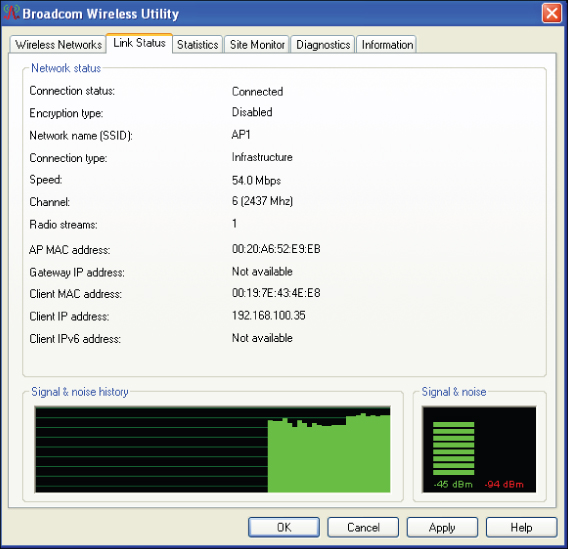
The amount of received signal strength required will be determined by the type or application of the wireless device as well as the amount of radio frequency noise in the area. RF noise consists of extraneous undesired radio signals in the area emitted by a variety of devices other than the transmitter. You should check with the device manufacturer to determine the minimum amount of received signal that is acceptable for a specific application. Some applications will require more received signal than others. For example, the manufacturer of a voice handset may recommend a minimum of –65 dBm to –67, dBm whereas a computer network card may require a minimum of –70 dBm.
The signal-to-noise ratio (SNR) is the difference between the received signal and the noise floor. For example, if the received signal is –65 dBm and the noise floor is –95 dBm, then the signal-to-noise ratio will be 30 dB. This value is calculated by subtracting the received signal from the noise. In this case –65 dBm – (–95 dBm) = 30 dB.
![]()
![]()
Testing Antenna Use
In Chapter 7, “Wireless LAN Antennas and Accessories,” we looked at various types of antennas, including omnidirectional, semidirectional, and highly directional models. The characteristics and features of these antennas were discussed, as well as the best use for each based on a specific scenario. In Chapter 10 we looked in more detail at the most common scenarios and the antenna choices they typically dictate. Here we'll consider how best to conduct antenna testing in a wireless LAN site survey
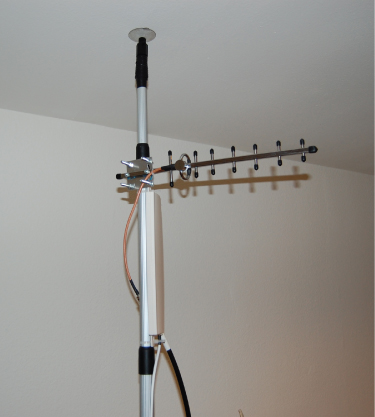
As part of a manual site survey, it may be necessary to test different antennas to determine the best RF coverage. This usually requires the surveyor to connect and temporarily mount various types of antennas to access points in order to determine the proper radiation pattern and to verify RF coverage within the desired area. Some predictive modeling site survey programs will allow you to change different antennas so you can see how that will change the RF propagation pattern. A temporary antenna mounting example is shown in Figure 11.16.
Figure 11.16 Expandable light pole used for temporary mounting and testing of Yagi and Patch antennas
Testing Multiple Antenna Types
If different antennas will be used in the deployment, it is important for the surveyor to have several types of antennas as part of the site survey kit. Some organizations that deploy wireless networks are extremely concerned about aesthetics; they will allow only specific types of antennas to be used. For example, if access points with removable antennas are used, in many cases the only type allowed will be omnidirectional antennas that are attached directly to the access point with a gain of about 2 or 3 dBi. Other deployments may use access points in which antennas are permanently part of the access point and cannot be removed or changed.
Choosing the Correct Antennas
Choosing the correct antenna to be used in a specific deployment is part of the wireless design and site survey process. Many factors play a role in determining which antenna will be best for the application. Some locations have strict requirements about the type of antenna that may be used. Therefore, the surveyor may have to work with specific antennas to ensure proper RF coverage. Take the following factors into consideration when choosing antennas:

Wireless Channel Architectures
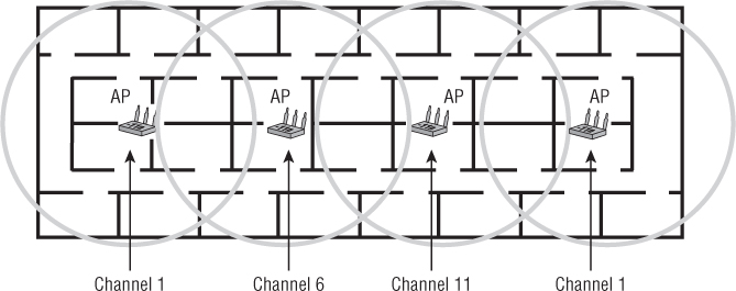
There are two common types of channel architectures available today that pertain to IEEE 802.11 wireless LAN technology. In wireless LAN technology, channel architecture is the design, layout, or channel plan in use. In the 2.4 GHz band, for example, the use of nonoverlapping channels 1, 6, and 11 is a channel architecture. The CWNP program defines these two wireless LAN architectures as multiple-channel architecture (MCA) and single-channel architecture (SCA).
Multiple-Channel Architecture
Most wireless LAN deployments today use multiple-channel architecture (MCA). This type of installation will use access points set to different RF channels in order to avoid overlapping channel interference, as shown in Figure 11.18. A channel plan may be used with access points set to specific channels, or in many cases automatic channel selection allows the devices to choose the best channel to operate on. Until recently this is how all wireless LAN access points were deployed.
Figure 11.18 An example of multiple-channel architecture deployment
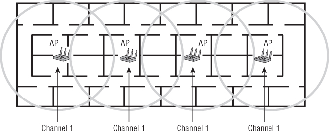
Single-Channel Architecture
Single-channel architecture (SCA) is a wireless networking technology available from only one manufacturer. SCA allows all access points to communicate on the same RF channel. The controller that the access points are connected to manages these access points and avoids co-channel interference. In single-channel deployments, not all access points are transmitting at the same time. The controller will determine which access points can transmit simultaneously based on the wireless devices that are in a specific area. A wireless LAN site survey for SCA equates to providing radio frequency coverage based on the access point placements as the wireless LAN controller manages all the radio frequency.
There are a few terms you should know with respect to single-channel architecture: stacking, spanning, and blanketing. They all refer to a means of managing coverage in a single-channel architecture.
For example, let's look at a three-story building. Each floor in the building may be assigned a channel to use; with SCA architecture this is known as stacking. The first floor would be set to channel 1, the second floor would be set to channel 6, and the third floor would be set to channel 11. Since all access points on the same floor are set to the same RF channel, co-channel interference or overlapping channel interference is not a significant issue because of how the SCA technology works.
Using single-channel architecture may help save some time when it comes to the site survey. It is best to follow the manufacturer's recommendations for deployment for this type of system. Figure 11.19 shows an example of single-channel architecture.
Figure 11.19 An example of single-channel architecture deployment
Wireless Device Installation Limitations
The installation limitations of any device that will be installed and used on the wireless network need to be evaluated. Sometimes things look great on paper, but when it comes time to actually perform the task it may be a little different. The installation limitations of various wireless devices include the following:
- Mounting issues
- Cabling issues
- Aesthetics
- Height restrictions
Site Survey Report
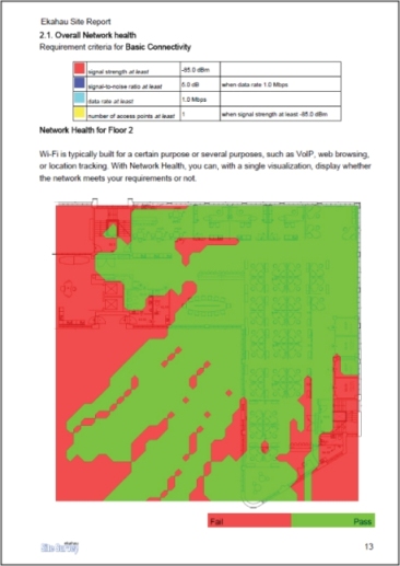
The survey report should be a complete document itemizing all components of the wireless site survey. This includes the business aspects of the wireless site survey as discussed in Chapter 10 as well as the physical aspects of the wireless site survey as discussed in this chapter. This report should include but not be limited to notes, charts, graphs, photos, test results, and any other pertinent data that will have an effect on the wireless LAN deployment. Most reports will be of a custom nature based on the individual needs and requirements of the customer. Most commercial site survey application programs have built-in reporting features that can be included in the site survey report. Figure 11.20 shows a sample page from a commercial site survey application with report generation features.
The main content of the site survey report should include:
- Customer requirement analysis
- Radio frequency interference source analysis
- Radio frequency coverage analysis
- Device capacity and application analysis
- Infrastructure device placement and configuration information
As I mentioned in the earlier section “The Physical Radio Frequency Site Survey Process,” the RF dynamics of many environments are constantly changing as more devices using radio frequency for communications become a part of the wireless LAN or share the same RF space. It is a wireless network engineer's responsibility to understand that site requirements may also be constantly changing. Therefore the RF site survey is becoming an ongoing process, and the site survey report can be seen as a living document. You can download a sample site survey report from Ekahau at this book's companion website: www.sybex.com/go/cwts2e.
Figure 11.20 Ekahau site survey built-in reporting features
Summary
In this chapter, you learned about the wireless LAN site survey process. This process is one of the most important components of a successful wireless LAN deployment. Many areas need to be considered, including an RF spectrum analysis to determine RF interference sources that may affect the wireless deployment. Although a spectrum analysis can be considered optional, it is advisable to complete one whenever possible. Keep in mind the spectrum analysis is based on a walkthrough of a facility and recording data at an instant in time. The results of this type of spectrum analysis can change once the surveyor has left the area. Spectrum analyzers are available in various types, consisting of instrumentation devices, PC card–based, USB adapters, and now may be part of the wireless access point.
In this chapter we compared Wi-Fi and non-Wi-Fi sources of interference, both which can have an effect on the performance of a wireless LAN installation. It is important to understand the various sources of interference, such as:
- Microwave ovens
- Bluetooth devices
- Radar systems
- Devices that operate in the ISM band
- Devices that operate in the UNII band
- Other IEEE 802.11 wireless LANs
We looked at the various types of wireless site surveys that can be performed, including manual and predictive modeling. We also explored the two types of manual site surveys, passive and active. Passive surveys see all RF from access points in the hearing range of the survey device. An active survey requires an association to a specific access point. Manual site surveys typically require a walkthrough of the entire area. Predictive modeling site surveys perform a simulated analysis of the proposed space where the wireless LAN will be deployed. The accuracy of a predictive survey is dependent on the information input to the program. Both manual and predictive site surveys can be simplified by using a variety of software programs made specifically for this function.
We discussed some of the items that may be included in a survey toolkit as well as temporary mounting examples for access points and antennas. We looked at the use of a protocol analyzer in a wireless site survey and how one could be used to identify existing wireless networks in the area of concern.
Finally, you learned about both multiple-channel architecture (MCA) and single-channel architecture (SCA) and the differences between them. Best practices for hardware placement were also reviewed, including access points and antennas as well as some of the limitations that may be encountered during the wireless LAN site survey process.
Exam Essentials
Review Questions
1. A main objective of a wireless LAN site survey is to determine and . (Choose the best two options.)
A. Areas of RF interference
B. Applications to be used
C. Access point locations
D. Wiring closet locations
E. Security implementations
2. You are a network engineer tasked with performing a site survey for a multiple-channel architecture (MCA) system in a three-story building. Which characteristic must be considered while performing a site survey?
A. All omnidirectional antennas should be vertically polarized.
B. Multiple floors require the same channel.
C. Each floor should be treated as an individual site survey.
D. The channel plan should take all three floors into consideration.
3. What devices, tools, or programs can be used in a manual site survey? (Choose two.)
A. Spectrum analyzer
B. Passive scanning utility
C. Predictive site analyzer
D. Association analyzer
E. Authentication analyzer
4. The manual site survey consists of which possible methods? (Choose two.)
A. Passive
B. Scanning
C. Active
D. Spectrum
E. Packet
5. Non-Wi-Fi interference for an 802.11g network can be caused by and . (Choose two.)
A. AM radios
B. Microwave ovens
C. 802.11b networks
D. Cordless phones
E. Radar systems
F. Digital TV systems
6. You are a network consultant hired to perform a manual site survey for a small office building. The wireless network to be installed will use data and voice. For backward compatibility, the customer needs to support 2.4 GHz equipment. To provide the highest quality of service for the voice application, you recommend that the received signal strength be a minimum of for a data rate of 54 mbps.
A. –20 dBm
B. –25 dBm
C. –67 dBm
D. –76 dBm
7. A type of site survey that is software-based, requires minimum time on-site, and takes into consideration the attenuation value of materials such as the type of walls and doors is .
A. Active
B. Passive
C. Predictive
D. Optional
8. You are performing a protocol analysis in order to determine potential interference from other wireless LANs in the immediate area of the site survey. You discover several wireless LANs that can potentially cause interference with the proposed installation. Which technology in use would not have an impact on the 802.11g wireless network you are surveying for?
A. FHSS
B. OFDM
C. DSSS
D. ERP-OFDM
E.PBCC
9. You are using a wireless client adapter with a site survey utility and a notebook computer to perform a manual site survey in a very small office building. Which values are important to record to verify proper RF coverage for the location? (Choose two.)
A. Signal strength
B. SNR
C. Packet retries
D. Signal loss
E. Propagation loss
10. You have been hired by a company to perform a manual site survey. When explaining the difference between a manual and predictive modeling site survey, you let the customer know the advantages and disadvantages of each. A manual site survey has which advantage?
A. Speed
B. No hardware required
C. Accuracy
D. Facility access not required
11. A spectrum analyzer can be used to view what?
A. Radio frequency
B. Wireless packets
C. Data rates
D. Association frames
12. You have been hired by a company to perform a wireless LAN site survey in a multitenant building. You discover numerous access points on channels 1, 6, and 11. To optimize the new deployment, what recommendation could you make to the customer? Assume that all new hardware will be purchased and backward compatibility is not required.
A. Configure the access points to automatic channel selection for the 2.4 GHz ISM band.
B. Configure the access points to operate in the 5 GHz band.
C. Perform a spectrum analysis to find space in the 2.4 GHz band.
D. Perform a predictive modeling site survey to determine which channels to use.
13. Which of the following is true of a predictive modeling survey?
A. It takes more time than a passive survey to get accurate results.
B. It takes less time than a passive survey to get accurate results.
C. It finds areas of interference from neighboring wireless LANs.
D. It helps you choose the manufacturer's equipment to be used for the wireless LAN.
14. When using a predictive modeling site survey approach, which of the following is true about manual verification?
A. Manual verification never has to be performed.
B. Manual verification is always required.
C. Manual verification should be performed only at the customer's request.
D. Manual verification should be performed, but it is not required.
15. When performing a manual site survey, choose the best way to identify areas that lack RF coverage.
A. Mark them with tape so they can be located at a later time.
B. Use a camera to take a photograph and document it in the report.
C. Show the site manager the areas that lack coverage.
D. Document on the floor plans or blueprints.
16. When a device associates to an access point during a site survey, it is performing what type of survey?
A. Predictive
B. Active
C. Passive
D. Required
17. When considering the use of antennas for wireless LAN deployment during a site survey, which antenna could be tested to verify proper coverage for a long hallway or corridor?
A. High-gain omnidirectional
B. Low-gain omnidirectional
C. Parabolic dish
D. Yagi
18. You need to perform a site survey for a small real estate office that currently has no wireless network. Which factors must be considered as part of the site survey?
A. Spectrum analysis
B. Packet analysis
C. Environmental conditions
D. Correct antenna selection
19. Co-channel interference is caused by access points on .
A. Channels 1 and 1
B. Channels 1 and 2
C. Channels 1 and 6
D. Channels 1, 6, and 11
20. Which guidelines are recommended when performing a manual site survey? (Choose two.)
A. Walkthrough of location
B. Predictive analysis
C. Equipment purchase
D. Client device configuration
E. Spectrum analysis