
Chapter 6
Radio Frequency Fundamentals for Wireless LAN Technology
The following CWTS exam objectives are covered in this chapter:
- 1.2 Define basic characteristics of and concepts relating to Wi-Fi technology
- Range, coverage, and capacity
- Frequencies/channels used
- Channel reuse and co-location
- 3.1 Define the basic concepts and units of RF measurements, identify when they are used, and perform basic unit conversion
- Watt (W) and milliwatt (mW)
- Decibel (dB)
- dBm
- dBi
- RSSI
- SNR
- 3.2 Identify and explain RF signal characteristics
- Frequency
- Wavelength
- Amplitude
- Phase
- 3.3 Identify factors which affect the range and rate of RF transmissions
- Line-of-sight requirements
- Interference (Wi-Fi and non-Wi-Fi)
- Environmental factors, including building materials
- Free space path loss
Radio frequency (RF) plays an essential role in wireless LAN technology. Radio waves are passed through the air (which is the medium) and are used to get information from one wireless device to another. Technically speaking, with respect to wireless LANs, RF consists of high-frequency alternating current (AC) signals passing over a copper cable connected to an antenna. The antenna then transforms the signal into radio waves that propagate through the air from a transmitter to a receiver.
Unlike wired devices, which use physical cable to communicate, wireless LANs use the radio waves and the air to communicate. This chapter will discuss the characteristics of RF and explain how far a radio signal will travel depending on various factors, the area covered by the radio frequency propagation, and some of the factors determining how many clients or devices can use the RF signals for data communications. This chapter will also explain the range and speed of RF transmissions. Range (how far radio waves will travel) and speed can be affected by several environmental conditions or behaviors, such as reflection and refraction. Additionally, this chapter will examine some of the conditions that affect the transmission of information across the air, including interference.
Understanding RF units of measure such as watts (W), milliwatts (mW), and decibels (dB) is important to RF work, just as understanding denominations of money such as U.S. dollars and British pounds is an important part of daily life. We will discuss RF signal measurements, including received signal strength indicator (RSSI) and signal-to-noise ratio (SNR).
Understanding Radio Frequency
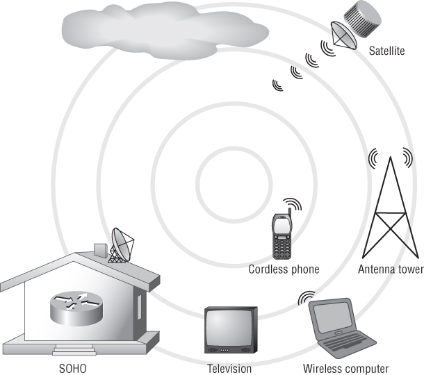
Radio frequency (RF) waves are used in a wide range of communications, including radio, television, cordless phones, wireless LANs, and satellite communications. RF is around everyone and everything, and comes in many forms. RF energy is emitted from the numerous devices that use it for various types of communications. For the most part, it is invisible to humans. There is so much of it around, that if you could actually see RF, it would probably scare you. Don't let it scare you, however, because the amount of regulated RF power transmitted from the devices used in daily lives is harmless. Figure 6.1 shows some of the many ways RF is used. Studies have shown that the amount of power emitted from many of these devices, such as cordless telephones or wireless network adapters, will not cause any physical harm if the devices are manufactured not to exceed the maximum regulated power allowed for the device.
Figure 6.1 Radio frequency is used in many different devices to provide wireless communications.
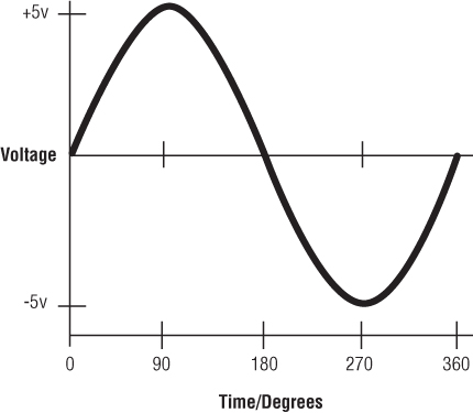
Remember, RF consists of high-frequency alternating current (AC) signals passing over a copper cable connected to an antenna. This antenna will then transform the received signal into radio waves that propagate through the air. The most basic AC signal is a sine wave. This wave is the result of an electrical current varying uniformly in voltage over a period of time. This sine wave cycle will repeat a specific number of times (cycles) over a period of one second. The number of cycles per second will result in different frequencies. Frequency is discussed later in this section. Figure 6.2 shows a basic sine wave.
Figure 6.2 A basic sine wave, one complete cycle varying voltage at a point in time
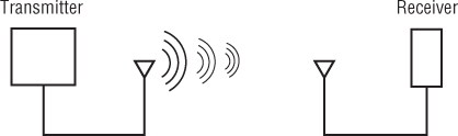
Successful radio transmissions consist of a minimum of two components, a transmitter and receiver (see Figure 6.3). With IEEE 802.11 wireless networking, a wireless station can transmit and receive and is known as a transceiver. These two components work together: For every radio transmitter there must be one or more radio receivers. It is important to understand the basic characteristics of radio frequency transmissions. These characteristics work together to form alternating current signals and include the wavelength, frequency, amplitude, and phase. The antenna will transform these signals into radio waves that travel through the air carrying information from the transmitter to the receiver. This is accomplished in different ways depending on the wireless technology in use. This theory will be discussed more in Chapter 7, “WLAN Antennas and Accessories.”
Figure 6.3 RF transmitter and receiver. In a wireless LAN, the transmitter and receiver could be an access point and client device.
Wavelength in Wireless LANs
The wavelength is the distance of one complete cycle or one oscillation of an AC signal. Wavelength is typically identified by the Greek symbol lambda (), which is used in formulas for calculations. This distance is usually measured in centimeters or inches. Figure 6.4 shows an example of a wavelength.
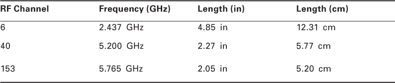
IEEE 802.11 wireless LANs use both the 2.4 GHz and 5 GHz unlicensed frequency ranges for transmission. The IEEE 802.11-2012 Standard also specifies some additional frequency ranges in which wireless LANs can operate. Although these do not fall under the “unlicensed” category, 4.9 GHz public safety and 3.650 GHz (IEEE 802.11y amendment) can also be used for IEEE 802.11 wireless LAN communications. Table 6.1 lists some examples of wavelengths for IEEE 802.11 wireless LANs using unlicensed frequencies.
Figure 6.4 The wavelength is the distance of one complete cycle, measured in centimeters or inches.

Table 6.1 Typical radio transmission wavelengths for WLANs
Frequency in Wireless LANs
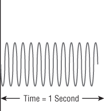
Frequency is defined as the number of complete cycles in one second. Low frequencies correspond to long waves and high frequencies to short waves, so the higher the frequency, the shorter the wavelength (range). In formulas, frequency is typically identified by the lowercase letter f.
Figure 6.5 shows an example of frequency.
Figure 6.5 Frequency is the number of complete cycles in 1 second.
IEEE 802.11 wireless LANs work in several unlicensed frequency ranges. The unlicensed ranges used for WLANs are 2.4 GHz to 2.5 GHz and 5.15 GHz to 5.875 GHz. There are some areas in the 5.15 GHz to 5.875 GHz range that are not used for standards-based wireless networking.
Amplitude in Wireless LANs
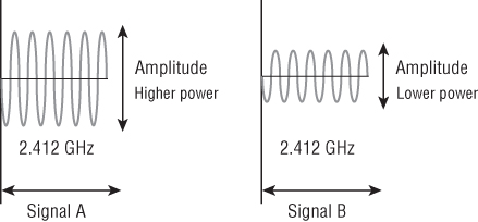
From a wireless LAN perspective, the amplitude is the strength or the amount of power of an RF signal. This is calculated from the height (in a two-dimensional view), on the Y axis of the sine wave, representing the voltage. As mentioned earlier, a basic sine wave is a change in voltage over a period of time. Using a formula, the voltage at the peak of the signal can be used to calculate the amount of RF power. So an increase in amplitude is equal to an increase in RF power. An increase in power is also known as gain. Conversely, any decrease in amplitude will be a decrease in power. A decrease in power is also known as loss. If a transmitter outputs a certain amount of RF power—for example, 100 mW—it has a specific amplitude of some value. As this signal travels through an RF cable, it will have a specific level of loss based on the cable in use, resulting in attenuation. Therefore the result will be less amplitude at the end of the cable due to the loss value of the cable.
Figure 6.6 shows two signals operating at the same frequency with different amplitudes. The signal with the higher amplitude (Signal A) is more powerful than the signal with the lower amplitude (Signal B).
Figure 6.6 Two signals at the same frequency with different amplitudes
Phase in Wireless LANs
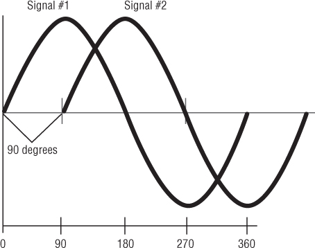
Phase is the difference in degrees at a particular point in the time of a cycle, measured from some arbitrary zero and expressed as an angle. For example, if a second sine wave starts a quarter of a wavelength after the first sine wave, it is considered to be 90° out of phase with the first sine wave. Figure 6.7 shows an example of the phase relationship between two AC signals. Two radio waves that have the same frequency but start at different times are known to have a phase difference and are considered out of phase with one another. The amount of the phase difference is typically measured in degrees ranging from 0° to 360°.
Figure 6.7 Phase is the difference in degrees between two signals.
Waves that arrive at a receiver out of phase will experience some level of distortion, which will cause corruption. This is known as multipath. The difference in time of arrival of the main signal and a reflected signal that causes the multipath problem is called the delay spread. If two waves arrive at a receiver 180° out of phase, this will usually result in a cancellation effect or nullify the two signals. Conversely, two waves that arrive in phase are additive, and this will result in an increase in signal strength known as upfade. Keep in mind, however, that the amplitude of the waves that experience the upfade effect will never be higher than the wave transmitted.
Radio Frequency Used in Wireless LANs
As discussed in Chapter 2, “Introduction to Wireless Local Area Networking,” RF spectrum is governed by local regulatory agencies. The country where the RF is used determines the regulations, such as frequency use and maximum power. Table 6.2 illustrates examples of local RF regulations.
Table 6.2 Local RF regulations
| Location | Regulation |
| Canada | ISC RSS-210 |
| China | RRL/MIC Notice 2003-13 |
| Europe (ETSI) | ETS 300.328ETS 301.893 |
| Israel | MOC |
| Japan (MKK) | TELEC 33BTELEC ARIB STD-T71 |
| Singapore | IDA/TS SSS Issue 1 |
| Taiwan | PDT |
| United States | FCC (47 CFR) Part 15C, Section 15.247FCC (47 CFR) Part 15C, Section 15.407 |
U.S. (FCC) Unlicensed Frequency Bands
In the United States, the Federal Communications Commission (FCC) is the local regulatory agency responsible for regulating licensed and unlicensed radio spectrum. Listed are the unlicensed RF bands available in the United States for use with wireless communications:
- ISM: Industrial, Scientific, and Medical
- 902−928 MHz (not specified for use with standards-based IEEE 802.11 wireless networks)
- 2.400−2.4835 GHz
- 5.725−5.875 GHz
![]()
- UNII: Unlicensed National Information Infrastructure
- 5.15−5.25 GHz: UNII-1, lower
- 5.25−5.35 GHz: UNII-2, lower middle
- 5.470−5.725 GHz: UNII-2e, upper middle
- 5.725−5.825 GHz: UNII-3, upper
The IEEE 802.11 standard addresses the 2.4 GHz ISM band and the 5 GHz UNII bands. In the United States, the 2.4 GHz ISM band allows for 11 of 14 total channels to be used for wireless LAN communications. The 5 GHz UNII band consists of four bands utilizing four frequency ranges: UNII-1, the lower band; UNII-2 and UNII-2e, the middle bands; and UNII-3, the upper band. Table 6.3 shows unlicensed frequency bands and channels used by IEEE 802.11 wireless LAN technology. Keep in mind that the 5.725-5.875 GHz ISM band is used where allowed by the regulatory agency.
Table 6.3 IEEE 802.11 frequency and channel allocations
| Band | Frequency | Number of channels |
| ISM | 2.400−2.4835 GHz | 14 |
| UNII-1 | 5.150−5.250 GHz | 4 |
| UNII-2 | 5.250−5.350 GHz | 4 |
| UNII-2e | 5.470−5.725 GHz | 11 |
| UNII-3 | 5.725−5.825 GHz | 4 |
| ISM | 5.725−5.8750 GHz | 1 |
![]()
Radio Frequency Channels
As you have seen, radio frequency is divided into bands. These bands can be further separated into channels. A channel is a smaller allocation of the radio frequency band. One familiar application in which this is accomplished is television. Until over-the-air television became available in digital format, television was allocated certain frequency ranges. Common television channels operated in the very high frequency (VHF) band—for example, channels 2 through 13 operated from 54 through 216 MHz. This frequency range was divided into 12 channels, allowing optimal use of the frequency range for the application, in this case television signals.
A viewer can change channels on a television to watch different programs running simultaneously. However, only one program can be viewed at any one time depending on which channel is currently selected. (Picture-in-picture televisions can show two or more channels at once on the screen, but each picture is still being received on a different channel.)
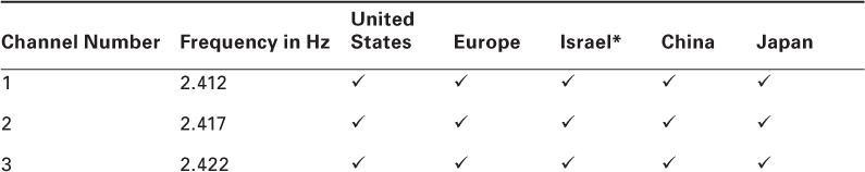
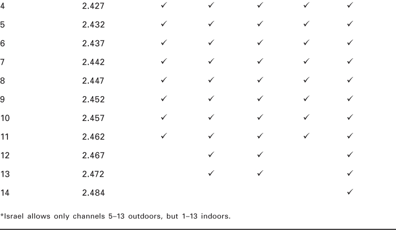
Wireless LANs use channels in the same way. Certain unlicensed frequency ranges are allocated for wireless networking, and those frequency ranges are subdivided into channels. In order for a transmitter and receiver to communicate with one another, they must be on the same channel. The 2.4 GHz ISM band has a total of 14 channels available for wireless networking. The locale where they are used will determine which of the 14 channels can be legally used for wireless networking. In the United States, IEEE 802.11b/g/n wireless networks use 11 of the 14 channels available in the 2.4 GHz ISM band. Each of these 11 channels for DSSS or HR/DSSS is 22 MHz wide, and for OFDM it is 20 MHz wide. Understand that these channels are further defined by their center frequency; for example, Channel 1 in the 2.4 GHz ISM band has the center frequency at 2.412 GHz. Simple mathematics show there will be overlap in order to accommodate all of the 20 MHz or 22 MHz wide channels in this frequency range. Table 6.4 shows the 14 available channels in the 2.4 GHz range.
Table 6.4 Channels in the 2.4 GHz ISM band
The 5 GHz UNII band is also divided into channels. This band consists of four bands—lower, lower middle, upper middle, and upper. These four bands consist of four different frequency ranges. Since there are fewer channels in the same amount of space, channels in the UNII band do not overlap. In the 5 GHz UNII band, channels are 20 MHz wide. Table 6.5 shows the 5 GHz UNII band for the FCC and ETSI locales.
Table 6.5 Channels in the 5 GHz bands
| Locale | Frequency | Number of channels |
| Americas/EMEA | UNII-1 band (5.15−5.25) | 4 |
| Americas/EMEA | UNII-2 band (5.25−5.35) | 4 |
| Americas/EMEA | UNII-2e band (5.470−5.725) | 11 |
| Americas/EMEA (with restrictions) | UNII-3 band (5.725−5.825) | 4 |
| Americas | ISM (5.725−5.850) | 1 |
Radio Frequency Range
Range for wireless LANs is based on the wavelength or distance of a single cycle. The higher the frequency, the shorter the range of the signal and the lower the frequency, the longer the range of the signal. At the same output power level, a 2.4 GHz signal will travel almost twice as far as a 5 GHz signal. If a network design is planning to use dual-band access points, range will need to be considered to ensure proper coverage for both the 2.4 GHz ISM and 5 GHz UNII bands. A wireless site survey will help determine the usable range an access point will produce. A survey can involve physically walking around the proposed space and/or predictive modeling using one of many software programs. This process is discussed further in Chapter 11, “Performing an RF Wireless LAN Site Survey.”
Wireless LAN Coverage and Capacity
Coverage and capacity are two key factors to take into consideration when designing and implementing an IEEE 802.11 wireless LAN. During the design phase of an IEEE 802.3 wired network, the design engineer will take capacity into account, verifying and validating that there are enough capacity switches, ports, and so on for the user base of the network. The same is true for a wireless network. The number of devices/users connected to an access point is something that needs to be carefully considered. The fact that wireless networks use a shared medium is an issue because the more devices that are connected to an access point, the lower the performance may be, depending on what the devices are doing. This capacity consideration will ensure satisfied end users and excellent network performance—proof of a successful wireless network design and deployment.
In wireless networks, coverage also needs to be considered. Coverage is determined by the RF cell size. In IEEE 802.11 wireless networks, a cell is the area of RF coverage of the transmitter, in most cases an access point. Depending on implementation, wide coverage or large cell size may not be the best solution. A large space covered by a single access point could result in less than adequate network performance based on factors such as the users' distance from the access point. The farther away from an access point, the less throughput a device or user will experience. If users will be scattered throughout a large space, it may be best to have several access points covering the space to allow for optimal performance.
![]()
Wireless LAN Coverage
The term coverage has different meanings depending on the context in which it used. For example, if you buy a gallon of paint, the label will specify the approximate coverage area in square feet. If one gallon of paint covers 300 sq ft and the room you wish to paint is 900 sq ft, simple math shows at least three gallons of paint would be needed to effectively cover the room.
The concept is similar in IEEE 802.11 wireless networking. However, unlike with paint, there is no simple rule that determines how much space an access point will cover with the RF energy it is transmitting. This coverage will depend on many factors, some of which include:
- Physical size of the area
- Bandwidth-intensive software applications in use or hardware applications may negatively impact the performance therefore requiring smaller RF coverage cells
- Obstacles, including building materials and propagation (the way radio waves spread through an area)
- Radio frequency range
- WLAN hardware in use (this affects coverage because higher frequencies, such as 5 GHz, do not travel as far as lower frequencies, such as 2.4 GHz)
- Transmitter output power
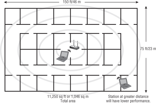
You might initially assume that you want the RF signal to propagate over the largest area possible. But this may not be the best solution. A very large cell may allow too many devices to connect to a single access point, causing a decrease in overall performance. For those client devices connected at a greater distance, the performance will be lower than for stations closer to the access point. Figure 6.8 shows a large coverage area, approximately 11,250 sq ft (1,046 sq m) covered with a single access point. This is an example of too large an area for a single access point.
Figure 6.8 Wide coverage with only a single access point is not recommended.
Physical Size of the Area
Rarely, if at all, will a manufacturer of enterprise-grade IEEE 802.11 wireless LAN hardware commit to the amount of area an access point will cover. There are too many variables to take into consideration, which makes it difficult to specify an exact number. However, some manufacturers may estimate the effective range of the device or access point. A site survey of the area will help determine the coverage area of an access point. A manual survey will allow for testing to verify the distance a signal will travel. A predictive site survey will model the environment and determine the signal propagation. This concept will be discussed further in Chapter 11.
Applications in Use
The application types in use—either software or hardware—can affect the bandwidth of an access point. If the devices connected to an access point use bandwidth-intensive applications such as a computer-aided design/computer-aided manufacturing (CAD/CAM) application, it could result in poor throughput for all devices or users connected to that access point. This is another example where more access points, with each covering a smaller area, could be a better solution than a single access point covering a large area. Multiple access points could allow the high-bandwidth users to be separated from other parts of the network, increasing overall performance of the network.
Obstacles, Building Materials, Propagation, and RF Range
Obstacles in an area, including building materials such as walls, doors, windows, and furnishings, as well as the physical properties of these obstacles—thickness of the walls and doors, density of the windows, and type of furnishings—can also affect coverage. The radio frequency used—either 2.4 GHz or 5 GHz—will determine how well a signal will propagate and handle an obstacle.
For example, a wall made from sheetrock or drywall materials may have an attenuation value of about 3 dB to 4 dB, whereas a wall made of concrete may have an attenuation value of about 12 dB. Therefore the sheetrock wall would have less impact on the RF propagation than the concrete wall. Partitions, walls, and other obstacles will also determine the coverage pattern of an access point because of the way RF behaves as it travels through the air. Behaviors of RF will be discussed later in this chapter in the section “Environment: RF Behavior.”
WLAN Hardware and Output Power
The wireless LAN hardware in use can also have an impact on the coverage area. Examples include the antenna type, antenna orientation, and gain of the antenna. The higher the gain of an antenna, the greater the coverage area; conversely, the lower the gain of an antenna, the smaller the coverage area. The polarization of an antenna (horizontal vs. vertical) will also have an effect on the coverage area because of the different shapes of the radiation patterns. The output power of the transmitter or access point will also have an effect on coverage. The higher the output power, the greater distance a signal will propagate. A higher power signal will provide more coverage. Most enterprise-grade access points provide the capability to control or adjust the output power.
Wireless LAN Capacity
One definition of capacity is the maximum amount that can be received or contained. An example of this would be an elevator in a building. Typically an elevator will have a maximum number of people or amount of weight it can hold; this is usually stated on a panel within the elevator. To ensure safety, the elevator may have a safety mechanism to prevent overloading. Likewise, a restaurant has a certain number of chairs to hold customers; therefore, they would have a maximum capacity of customers who can be served at any one time. Does this mean that when a restaurant fills its seats to capacity, the doors close and no other customers can enter the building? Not necessarily. In some cases, a restaurant could have customers standing and waiting to be seated.
Just as an elevator or a restaurant has a limited number of people they can accommodate comfortably, wireless access points also have a limited number of devices they can handle, known as capacity. The capacity of an access point is how many devices or users the AP can service effectively, offering the best performance. This capacity depends on several factors, including:
- Software and hardware applications in use
- Desired throughput or performance
- Number of devices/users
The following sections discuss how these factors affect the capacity of an access point.
![]()
Software and Hardware Applications in Use
The software and hardware applications in use may affect the capacity of an access point. Some applications are more bandwidth-intensive than others. For example, word processing applications may not require much bandwidth whereas database or CAD/CAM applications may require much more bandwidth than other applications. If high-bandwidth applications are in use, the contention among the connected users will increase because they are using a shared medium (air and RF). Therefore performance will potentially be reduced for all users connected to the access point. The access point is providing the same amount of bandwidth, but the overall performance has been decreased for the connected users because the software applications are all using a lot of bandwidth.
The use of Voice over Wireless LAN (VoWLAN) technology is also increasing steadily in many wireless network deployments. This is an example of a hardware application. Voice technology on wireless networks is subject to latency. Therefore, depending on the number of voice client devices connecting to an access point, the network must be carefully planned. Capacity planning and quality of service (QoS) features are important when it comes to deploying voice technology on wireless networks.
Desired Throughput or Performance
The desired throughput or performance can also affect capacity. A large number of users connected to an access point using a bandwidth-intensive application will cause poor performance. Therefore, it may be necessary to limit the capacity to a certain number of users to give the connected users the best performance possible. Any software application that is bandwidth-intensive, such as CAD/CAM, streaming video, or File Transfer Protocol (FTP) downloads, can have an effect on overall performance. One way to help resolve this would be to use load balancing to limit the number of users that can connect to an access point. Another way would be to create RF cells with smaller coverage and add more access points.
Number of Devices/Users
The number of devices or users in an area will also affect the access point capacity. A single access point covering a large area will potentially allow for a large number of devices connecting to the access point. For example, an office of 8,000 sq ft may consist of 100 people, each with their own wireless device. This is an example of wide coverage and large capacity. The software applications in use on the wireless network will have an impact on the overall performance. If all 100 devices connected are using a CAD/CAM application, which is a bandwidth-intensive application, the overall performance will be poor because this type of application requires a lot of resources. Therefore more access points, each covering less space and less capacity, would parlay into better overall performance for all of the users.
Wide coverage in a densely populated area may allow too many devices to connect to a single access point, resulting in poor performance overall. As you learned earlier, wireless LANs use what is known as a shared medium. In other words, all devices users connected to an access point will share the available bandwidth. Too many devices using powerful applications will overload the access point, adding to the poor performance issues. This scenario is considered a capacity issue. In this situation more access points with each AP covering a smaller area and a lower number of devices or less capacity would be a better solution. As you learned in Chapter 4, “Wireless LAN Client Devices,” many organizations now have to deal with the “Bring Your Own Device (BYOD)” issue.
In addition to potential problems with technical support and security, wireless LAN capacity is also a major concern. The BYOD expansion of Wi-Fi capable devices is causing a wireless client device density issue within the enterprise market. If a company's corporate policy allows employees to bring their own wireless capable devices, then wireless LAN capacity needs to be carefully evaluated to address this potential issue.
Radio Frequency Channel Reuse and Device Co-location
Earlier in this chapter, it was noted that the 2.4 GHz ISM band has a total of three nonoverlapping channels. In the U.S. FCC implementation of this band, the three nonoverlapping channels are 1, 6, and 11. This means there must be a separation of five channels in order for them to be considered nonoverlapping. In the 2.4 GHz ISM band, channels are separated by 5 MHz on center. Taking this into consideration, channels must be separated by 25 MHz or greater in order to be considered nonoverlapping (IEEE 802.11-2012, Clause 18). This is calculated from five channels of separation multiplied by 5 MHz on center (5 × 5 = 25). With deployments larger than a few access points, a channel plan may be necessary. A channel plan will minimize the chance of interference caused by two transmitters (access points) set to the same or adjacent overlapping channels.
![]()
Figure 6.9 illustrates a 2.4 GHz deployment with no channel planning. Users in the areas where the circles overlap will experience interference. This interference will result in lower overall throughput for the connected users because of the Physical layer (PHY) technologies that wireless LANs use. This interference basically has the same effect as collisions in an Ethernet network, resulting in retransmissions of data.
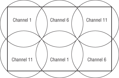
A correct channel plan will implement channel reuse and ensure that overlapping cells will not use overlapping channels. Channel reuse is using non-overlapping channels—for example 1, 6, and 11 in the 2.4 GHz range—in such a way that the overlapping cells are on different RF channels. Figure 6.10 shows a 2.4 GHz deployment utilizing proper channel reuse. Channel reuse may be accomplished by mapping out the access points on a floor plan and minimizing the chances that the RF cells propagated by the access points do not overlap on the same RF channels. This type of channel plan can de done manually or with site survey software applications. Site survey applications will be discussed in more detail in Chapter 11.
Figure 6.9 Users of these access points will experience overlapping channel interference in a multichannel architecture because they are all set to the same channel.

Figure 6.10 Co-location of access points with proper channel reuse. Overlapping areas use different channels in a multichannel architecture to prevent interference.
Radio Frequency Range and Speed
How far and fast a radio frequency signal can travel depends on a variety of factors, including line of sight, interference, and the types of materials in the environment. This section discusses these factors.
Line of Sight in Wireless Networking
Radio frequency communication between devices in 802.11 wireless networking uses different types of line of sight. There are two types of line of sight to take into account when planning, designing, and installing wireless networks:
- Visual line of sight
- Direct link radio frequency (RF) line of sight
Visual line of sight is when a transmitter and receiver can “see” each other. In order for wireless networking direct link communication to be successful in an outdoor wireless link, there should be a clear, unobstructed view between the transmitter and receiver. An unobstructed line of sight means few or no obstacles blocking the RF signal between these devices.
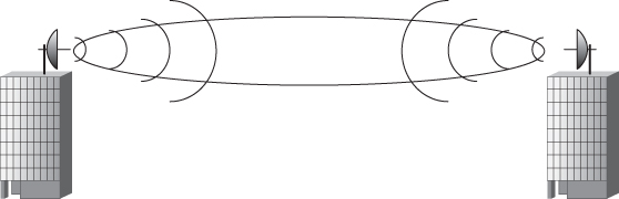
In an outdoor wireless LAN installation, direct RF line of sight is an unobstructed line between a radio transmitter and receiver. This line will be surrounded by an area of radio frequency transmissions known as the Fresnel zone. The Fresnel zone consists of a number of concentric ellipsoidal volumes that surround the direct RF line of sight between two points, such as an RF transmitter and receiver or two wireless bridges.
In outdoor wireless LAN installations, the RF line of sight, and therefore the radio transmissions between a transmitter and receiver, could be affected if the total area of the Fresnel zone is blocked by more than 40 percent. This blockage can come from a variety of sources, such as trees, buildings, terrain, or other obstacles, including the curvature of the earth over a distance of 7 miles or greater. Figure 6.11 illustrates a Fresnel zone.
Figure 6.11 The oval area represents the Fresnel zone RF coverage area between a transmitter and receiver, two wireless bridges.
One way to think about line of sight is by the analogy of two people looking at each other. If two people about the same height standing some distance apart are making direct eye contact, they have a good visual line of sight. In addition to being able to see directly in front of them, people have peripheral vision. This peripheral vision gives people the ability to see movement and objects outside of their direct line of sight or direct eye contact. This peripheral vision or side vision is analogous to the Fresnel zone theory.

Because of the low transmit and receive power and the short distance, a visual line of sight is not required for an indoor wireless LAN deployment. An indoor access point may cover areas that are divided by walls and other obstacles. With this short range and if the radio frequency is able to penetrate the obstacles, wireless communication between a transmitter and a receiver will be successful even when the devices do not have a visual line of sight.
Wi-Fi and Non-Wi-Fi Interference
Interference from a radio frequency point of view occurs when a receiver hears two different signals on the same or close frequency. Interference causes received radio frequency signals to be distorted. In wireless LANs, this interference can have a severe impact on the quality of signal received by a wireless device. This distorted or corrupted signal will decrease the amount of data a device can effectively receive, thereby causing less data throughput.
A wireless LAN receiver has similar characteristics to the human ear. Both can hear a range of frequencies. If one person is speaking and a number of people are listening to this speaker, that is analogous to a single transmitter and multiple receivers. If a second person started to speak at the same time, people listening might not be able to understand either speaker. In a sense, they are experiencing interference.
As discussed earlier in this chapter, an IEEE 802.11 wireless network may use the unlicensed 2.4 GHz industrial, scientific, and medical (ISM) band. This band is also used for many other devices, including:
- Cordless phones
- Microwave ovens
- Medical devices
- Industrial devices
- Baby monitors
- Other IEEE 802.11 wireless networks
Because these devices also use radio frequency to operate, and the frequency is in the same unlicensed band as IEEE 802.11 wireless networks, they have the potential to interfere with one another. Although they may coexist in the same RF space, the interference factor needs to be taken into consideration. This can be done as part of the site survey process.
Co-channel and Adjacent Channel Interference
Co-channel or adjacent channel interference occurs when two devices in the same physical area are tuned to close radio frequency channels or the same channel. For example, an access point on channel 1 and another access point on channel 2 in close or hearing range of each other will experience adjacent channel interference. Some of the symptoms of this type of interference are reduced throughput and the equivalent of collisions causing data retransmissions. A new term being used for co-channel interference is “co-channel cooperation,” since it is not really interference but rather an increase in the size of the contention domain.
![]()
Overlapping interference is defined as two devices (such as access points) on the same frequency overlapping one another. For example, two access points in close proximity to each other, one on channel 1 and the other on channel 3, might interfere with each other.
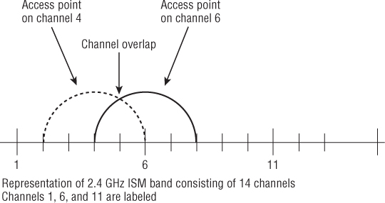
Both adjacent channel interference and co-channel channel interference will cause poor throughput on a wireless network. In a wireless network, co-channel or adjacent channel interference can have the same impact. Figure 6.12 shows that 2.4 GHz ISM band channel 4 and channel 6 overlap.
Figure 6.12 Channel overlap in the 2.4 GHz ISM band
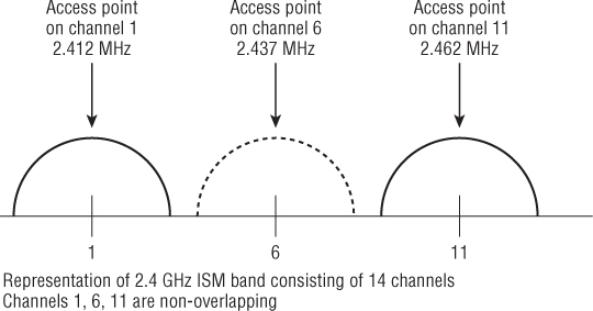
A properly designed wireless LAN will have overlapping RF cells. Overlapping cells provide continuous coverage for the entire area where the access points are placed. Overlapping cells allow devices to move from one access point to another and maintain a constant connection. A well-designed wireless LAN will also minimize or eliminate overlapping channel interference. This design includes assigning nonoverlapping RF channels to cells that do overlap with each other. In practice, an overlapping cell design will include a 20 to 30 percent overlap to encourage better roaming. Wireless repeaters require a 50 percent overlap to be effective. The frequency in use is determined by how many nonoverlapping channels are available in the band. For example, in the United States, the 2.4 GHz band used for 802.11b/g/n has three nonoverlapping channels—1, 6, and 11. Figure 6.13 shows 2.4 GHz ISM band with three nonoverlapping channels, channels 1, 6, and 11.
Figure 6.13 Five channels of separation and 25 MHz of separation between nonoverlapping channels
WLAN/WPAN Interference
The performance of IEEE 802.11 wireless networks can be affected when they are co-located with IEEE 802.15 wireless personal area networks (WPANs). Bluetooth is an example of a wireless personal area network. Like 802.11, Bluetooth devices operate in the 2.4 GHz frequency range and use frequency hopping spread spectrum (FHSS) technology. This functionality in older Bluetooth devices could potentially interfere with IEEE 802.11 wireless networks. Newer versions of Bluetooth that use adaptive frequency hopping (AFH) have less chance of interfering with other wireless networks, including 802.11 wireless networks. Adaptive frequency hopping allows devices such as Bluetooth to adapt to the RF environment by seeking areas of interference and not operating in those specific frequency ranges. This will lessen the chances of 802.15 WPAN devices interfering with 802.11 WLAN devices. This newer technology is proven such that WLAN 802.11 and WPAN 802.15 Bluetooth devices may coexist in the same physical radio chipset.
Environment: RF Behavior
In addition to various types of radio frequency interference, the interaction between RF and the surrounding environment can also affect the performance of IEEE 802.11 wireless networks. RF behavior is the result of environmental conditions, including:
- Reflection
- Refraction
- Diffraction
- Scattering
- Absorption
- Diffusion
Reflection
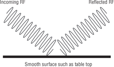
Reflection occurs when an RF signal bounces off a smooth, nonabsorptive surface such as a table top and changes direction. Reflections can affect indoor wireless LAN installations fairly significantly in certain cases. Depending on the interior of the building—such as the type of walls, floors, or furnishings—there could be a large number of reflected signals. If not properly handled, reflections could cause a decrease in throughput and poor network performance. Figure 6.14 illustrates reflection.
Figure 6.14 Radio frequency reflection
![]()
Refraction
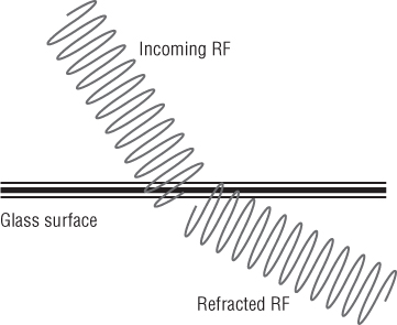
When an RF signal passes between mediums of different densities, it may change speeds and also bend. This behavior of RF is called refraction. Glass is an example of material that may cause refraction. When an RF signal comes in contact with an obstacle such as glass, the signal is refracted (bent) as it passes through and some of the signal is lost. The amount of loss depends on the type of glass, its thickness, and other properties. Figure 6.15 shows refraction.
Figure 6.15 Radio frequency refraction
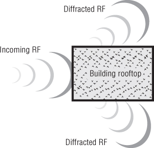
Diffraction
When an RF signal passes an obstacle, the wave changes direction by bending around the obstacle. This RF behavior is called diffraction. A building or other tall structure could cause diffraction, as could a column in a large open area or conference hall. Figure 6.16 illustrates diffraction. When the signal bends around a column, building, or other obstacle, the signal weakens, resulting in some level of loss.
Figure 6.16 Radio frequency diffraction
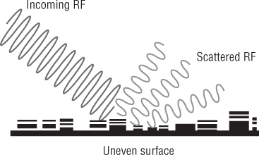
Scattering
When an RF signal strikes an uneven surface, wavefronts of the signal will reflect off the uneven surface in several directions. This is known as scattering. Scattering, illustrated in Figure 6.17, is another form of loss that may severely degrade the RF signal.
Figure 6.17 Radio frequency scattering
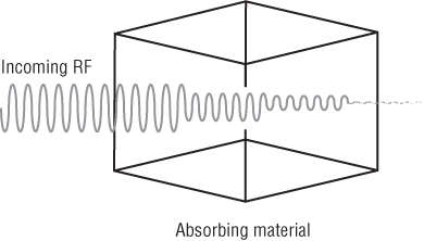
Absorption
When material absorbs an RF signal, no signal penetrates through the material. An example of absorption is the human body. The human body has a high water content and will absorb RF signals. This type of absorption can be a problem for wireless network deployments in certain environments. Densely populated areas such as airports and conference halls need to consider absorption when designing a wireless LAN deployment. Figure 6.18 shows absorption.
Figure 6.18 Radio frequency absorption
Diffusion
Diffusion occurs when the RF signal naturally widens as it leaves an antenna element. As a result of this widening effect, the transmitted radio frequency signal will decrease in amplitude and be less powerful at any distance from the antenna. This is known as free space path loss (FSPL). FSPL is the greatest form of loss factor in a radio frequency link. FSPL is calculated using frequency and distance as variables and entered into a mathematical formula. The receiving antenna is only able to receive a small amount of the transmitted signal because of this widening effect of the diffused signal as it propagates through the air. Any signal that is not received by the intended device is considered loss.
Basic Units of Radio Frequency Measurement
If a person were given a dollar bill, they would be one dollar richer. If this person were given 100 cents, they would still be one dollar richer. From this example, we see 1 dollar = 100 cents and 1 cent = 1/100th of a dollar. One dollar and 100 cents are the same net amount, but a cent and a dollar are different units of currency.
The same is true for radio frequency measures of power. The basic unit of measure for radio frequency is the watt. A wireless access point may be set to an output of 30 mW (milliwatts) of power. A milliwatt is 1/1000 of a watt. Just as in currency cents and dollars are both denominations of money, watts and milliwatts are measurements of RF power. Other units of measurement for RF are dB, dBi, dBd, and dBm.
Absolute Measurements of Radio Frequency Power
The amount of power leaving a wireless access point is one example of an absolute measure of power. This is an actual power measurement and not a ratio or a relative value. In other words, this is a measurable amount of power and can be determined with the proper instrument, such as a watt meter. A typical maximum amount of transmit output power from an access point is 100 mW.
The measure of AC power can be calculated using a basic formula. The formula is:
P = E × I
Power (P) equals voltage (E) multiplied by current (I).
A simple example would be to calculate the power from 1 volt and 1 amp. Using the given variables, the formula is:
P = 1 volt × 1 amp
The answer would be power = 1 watt.
![]()
Watt (W)
The watt (W) is a basic unit of power measurement. It is an absolute value or measurable value. Most wireless networks function in the milliwatt range. Power level in watts is a common measurement in long distance point-to-point and point-to-multipoint connections.
Milliwatt (mW)
One milliwatt (mW) is 1/1000 of a watt. This is a common value used in RF work and IEEE 802.11 wireless LANs. The output power of an access point typically ranges from 1 mW to 100 mW. Most enterprise-grade access points allow you to change the output power. Most SOHO-grade access points have a fixed output power, typically 30 mW. The milliwatt is also an absolute unit of power measurement.
Decibel Relative to a Milliwatt (dBm)
dBm is the power level compared to 1 milliwatt. This is based on a logarithmic function. A good rule to remember is 0 dBm = 1 mW. This value is considered as absolute zero. Using a formula or basic RF calculation rules, you can easily convert any milliwatt value to decibels: 100 mW = 20 dBm, for example.
The dBm is also an absolute unit of power measurement. A dB is an example of a change in power or relative measurement of power where dBm is measured power referenced to 1 milliwatt or an absolute measure of power. The next section discusses relative measurements of power.
![]()
Relative Measurements of Radio Frequency Power
Changes in radio frequency power are known as relative. dB and dBi are relative measurements of power. An example would be an RF amplifier. If the input power to an amplifier is 10 mW and the output power is 100 mW, the gain of the amplifier is 10 dB—a change in power.
If the input power to an antenna is 100 mW and the output power is 200 mW, the gain of the antenna is 3 dBi—a change in power. Both of these are examples of changes in power and are known as relative expressions of RF power.
Decibel (dB)
The decibel (dB) is a ratio of two different power levels caused by a change in power. Figure 6.19 shows how an amplifier will provide an increase or change in power.
Figure 6.19 Output doubled in power from 100 mW to 200 mW from amplifier with a gain or change in power of +3 dB
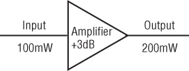
- 0 dBm = 1 mW (starting point)
- Increase by 3 dBm and power in mW doubles or × 2
- Decrease by 3 dBm and power in mW is cut in half or ÷ 2
- Increase by 10 dBm and power in mW is multiplied by 10 or × 10
- Decrease by 10 dBm and power in mW is divided by 10 or ÷ 10
Decibel Isotropic (dBi)
Decibel isotropic (dBi) is the unit that represents the gain or increase in signal strength of an antenna. The term isotropic in the RF world means energy broadcast equally in all directions in a spherical fashion. An imaginary, perfect antenna is known as an isotropic radiator. This is a theoretical concept and is used as a reference and in calculations. dBi will be discussed and used in more detail in Chapter 7. Table 6.6 shows a summary of absolute and relative power measurements.
Table 6.6 Absolute and relative measures of power
| Absolute power | Relative power |
| Watt | dB |
| Milliwatt | dBi |
| dBm | dBd |
![]()
Decibel Dipole (dBd)
The gain of some antennas may be measured in decibel dipole (dBd). This unit of measurement refers to the antenna gain with respect to a reference dipole antenna. The gain of most antennas used in wireless LANs is measured in decibel isotropic (dBi); however, some manufacturers may reference the gain of an antenna in dBd. The following simple formula derives the dBi value from the dBd value:
dBi = dBd + 2.14
This formula converts from dBi to dBd:
dBd = dBi − 2.14
![]()
Radio Frequency Signal Measurements
It is important to understand the various signal measurements of radio frequency used in wireless LAN technology. Using tools like a wireless adapter client utility or a spectrum analyzer will allow you to view different statistics that pertain to a wireless network. Some of these statistics are
- Receive sensitivity
- Radio frequency noise
- Received signal strength indicator (RSSI)
- Signal-to-noise ratio (SNR)
Receive Sensitivity
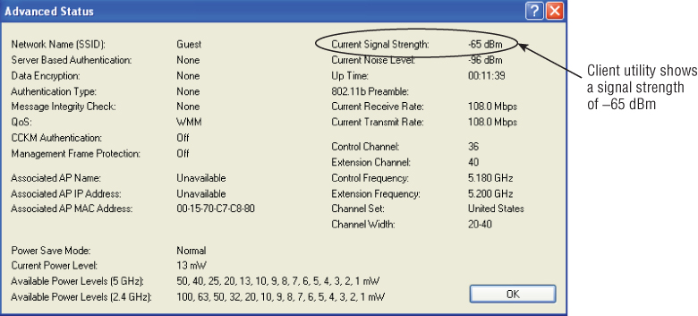
The basic definition of receive sensitivity is the measurable amount of radio frequency signal usable by a receiver. This is also determined by how much radio frequency noise is in the area of the radio receiver. Figure 6.20 shows a wireless adapter client utility that displays statistics, including the strength of signal received.
Figure 6.20 The Orinoco 8494-US IEEE 802.11a/b/g/n USB adapter shows the amount of signal received.
Radio Frequency Noise
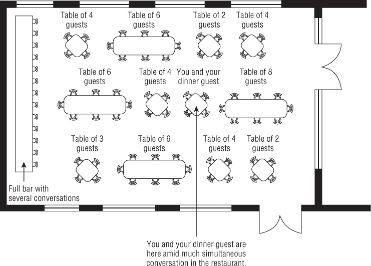
Radio frequency noise is the term for RF signals from sources other than the transmitter and receiver that are in communication. Here is an analogy to help explain. You and a guest are in a crowded open space restaurant for dinner. There are many unrelated conversations occurring at the same time at the various tables throughout the restaurant. If you and your dinner guest momentarily paused in your conversation, you would hear these other conversations, as well as the noise from equipment, telephones, and tables that are being cleared. This would be the restaurant equivalent of radio frequency noise, as shown in Figure 6.21.
Figure 6.21 Restaurant analogy example of radio frequency noise
In a wireless LAN environment several RF devices may be operating in the same physical space as the wireless transmitter (access point) and receiver (client device). Depending on the level of this radio frequency noise, it may be difficult for the transmitter and receiver to understand each other. In Figure 6.22 a screen capture from a noise analyzer utility shows a wireless basic service set on channel 40 in the 5 GHz UNII-1 band. Also shown is the radio frequency noise floor of about 95 dBm.
Figure 6.22 The MetaGeek Chanalyzer Pro software utility shows a noise floor for the tested site of about 95 dBm.

Received Signal Strength Indicator (RSSI)
Received signal strength indicator (RSSI) is an arbitrary number assigned by the radio chipset or device manufacturer. There is no standard for this value, and it will not be comparable between devices from different manufacturers. The calculation of the RSSI value is done in a proprietary manner and a wireless device from one manufacturer may indicate different signal strength than that indicated by another, even though they both are receiving the exact same signal and at the same actual amount of radio frequency power. This value is a key determinant of how well the wireless LAN device will perform. How the device is used with the network will determine the required levels of signal for optimal connectivity. Most wireless client device manufacturers allow their chipsets to access the higher data rates as long as they are getting a 70 dB signal or stronger. Wireless VoIP manufacturers recommend deploying so that the client devices can receive a 67 dB or better signal from the access point, a strength that is double the 70 dB required for higher data rate use due to the need for better signaling in QoS communications.
Signal-to-Noise Ratio (SNR)
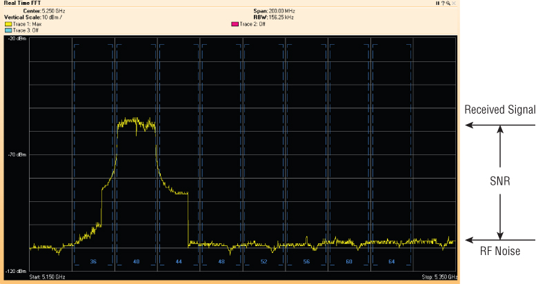
The signal-to-noise ratio (SNR) is the difference between the amount of received signal and the noise floor. Looking back at the restaurant analogy, if you were to continue your conversation and the tables surrounding yours were all speaking at higher volumes, you might not be able to hear your dinner guest very well, because of the amount of noise created in the open area of your table. Looking at this from a wireless LAN perspective, if a client device records a received signal of −85 dBm and the noise floor is −95 dBm, the signal-to-noise ratio will be 10 dB. This value is calculated by subtracting the received signal from the noise. In this case −85 dBm − (−95 dBm) = 10 dB. This would not be an adequate signal-to-noise ratio, because the receiver would have a difficult time determining the difference between the wanted RF signal and the surrounding RF noise. On the other hand, if the received signal is −65 dBm and the noise floor is −95 dBm, then the signal-to-noise ratio will be 30 dB. This value again is calculated by subtracting the received signal from the noise—in this case, −65 dBm − (−95 dBm) = 30 dB. This would be an excellent signal-to-noise ratio because the receiver would easily be able to determine the intended RF signal from the surrounding RF noise. Figure 6.23 illustrates the SNR as seen in a spectrum analyzer tool.
Figure 6.23 Graph showing the received signal strength vs. noise floor and the SNR using the Cisco Spectrum Expert spectrum analyzer utility.
Summary
This chapter explored radio frequency basics and the essential role RF plays in the world of IEEE 802.11 wireless networking. You learned the definition and understanding of RF as it pertains to wireless networking and the basic characteristics or properties of radio frequency such as:
- Wavelength
- Frequency
- Amplitude
- Phase
Then we described devices such as transmitters and receivers and how they communicate. In wireless LAN technology, an example of a transmitter and receiver is an access point and client device. We also discussed the unlicensed RF bands and channels used in the 2.4 GHz ISM and 5 GHz UNII ranges for wireless LAN communications as well as other frequency ranges that may be allowed for use with IEEE 80211 wireless networking depending on the local regulatory agency. Radio frequency coverage and capacity are two important areas that should be considered closely to ensure that a wireless deployment will offer reliable connectivity and perform well for the user base.
We then explained correct channel reuse to minimize interference from the co-location of access points. This chapter explored cause and effect of co-channel interference from sources other than wireless networks operating in the ISM and UNII bands. We also looked at RF behaviors such as reflection, refraction, and absorption, and the impact of building materials and the effect they have on the propagation of radio waves. We discussed RF units of measure both absolute and relative, including the watt, milliwatt, dB, and dBi. Finally we covered various types of radio frequency signal measurements used with IEEE 802.11 wireless networking. These topics included:
- Receive sensitivity
- Radio frequency noise
- Received signal strength indicator (RSSI)
- Signal-to-noise ratio (SNR)
Exam Essentials
Review Questions
1. What is the term defining the number of times a cycle of an RF signal will oscillate in one second?
A. Phase
B. Frequency
C. Amplitude
D. Wavelength
2. How many nonoverlapping channels are available in the unlicensed 2.4 GHz ISM band?
A. 1
B. 3
C. 6
D. 11
3. The capacity of an access point is dependent on which factors? (Choose two.)
A. Number of users
B. Channel reuse
C. Co-location
D. Software applications
E. Frequency
4. When an RF signal passes between media of different densities and may change speeds and bend, the behavior is known as:
A. Refraction
B. Reflection
C. Scattering
D. Diffraction
5. What two devices use RF to communicate? (Choose two.)
A. Transmitter
B. Transistor
C. Reactor
D. Reflector
E. Receiver
6. Which are relative measures of RF power? (Choose two.)
A. mW
B. dB
C. dBm
D. dBi
E. Watt
7. In the 2.4 GHz range, what distance between the center frequencies (in megahertz) is required for two channels to be considered nonoverlapping for HR/DSSS?
A. 5 MHz
B. 22 MHz
C. 25 MHz
D. 30 MHz
8. Two characteristics of RF signals are:
A. Amplitude
B. Reflection
C. Phase
D. Refraction
E. Diffraction
9. How many channels are available for wireless LANs to use in the unlicensed UNII-1 band?
A. 2
B. 4
C. 6
D. 11
10. Which are absolute measures of RF power? (Choose two.)
A. Watt
B. dB
C. mW
D. dBi
E. dBd
11. Which two channels are considered nonoverlapping in the 2.4 GHz band?
A. 1 and 6
B. 2 and 6
C. 6 and 10
D. 11 and 13
12. How many channels are available for wireless LAN use in the unlicensed 2.4 GHz ISM band?
A. 8
B. 10
C. 11
D. 14
13. The range of a 2.4 GHz signal is mostly dependent on which RF characteristic?
A. Frequency
B. Wavelength
C. Amplitude
D. Phase
14. Which item has an effect on RF line of sight?
A. Phase
B. Obstacles
C. Interference
D. Amplitude
15. How many channels are available for wireless LAN use in the unlicensed middle UNII-2e band?
A. 4
B. 6
C. 11
D. 14
16. As seen in a two-dimensional (X/Y) view, the amplitude of an RF signal is:
A. Height
B. Length
C. Shift
D. Width
17. An 802.11b channel is how wide in MHz?
A. 5 MHz
B. 22 MHz
C. 25 MHz
D. 30 MHz
18. When an RF signal bounces off a smooth nonabsorptive surface, the behavior is:
A. Refraction
B. Reflection
C. Scattering
D. Diffraction
19. What is the gain of an antenna measured in?
A. dB
B. dBc
C. dBi
D. dBm
20. When RF passes or bends around an obstacle such as a building or column, the behavior is:
A. Reflection
B. Refraction
C. Scattering
D. Diffraction