Chapter 8. Link Efficiency Tools
QoS Exam Topics
This chapter covers the following exam topics specific to the QoS exams:
![]() Explain the various link efficiency mechanisms and their function
Explain the various link efficiency mechanisms and their function
![]() Identify the Cisco IOS commands required to configure and monitor CB header compression
Identify the Cisco IOS commands required to configure and monitor CB header compression
![]() Given a list of link speeds and a specific delay requirement, determine the proper fragment size to use at each link speed and identify the typical delay requirement for VoIP packets
Given a list of link speeds and a specific delay requirement, determine the proper fragment size to use at each link speed and identify the typical delay requirement for VoIP packets
![]() Identify the Cisco IOS commands required to configure and monitor Multilink PPP with Interleaving
Identify the Cisco IOS commands required to configure and monitor Multilink PPP with Interleaving
![]() Identify the Cisco IOS commands required to configure and monitor FRF.12
Identify the Cisco IOS commands required to configure and monitor FRF.12
Most WAN links are leased from a service provider, with one of the variables affecting the pricing being the bandwidth on the link. For instance, the distance and the bandwidth, or clock rate, on the link affect leased line pricing. Frame Relay service providers base their prices in part based on the access rate of the access links into the Frame Relay network, and the committed information rate (CIR) of the various virtual circuits (VCs).
If the offered load on the network consistently exceeds the bandwidth or clock rate of the link the traffic must flow across, unpredictable behavior can result. For example, queues consistently fill, causing more delay, jitter, and drops. If the offered load far exceeds the clock rate for a period of time, most data applications slow down significantly, with voice and video streams possibly even becoming unusable. Depending on how you configure quality of service (QoS) in the network, some traffic types may perform as expected, but with a likely result of allowing some other traffic types to degrade even more quickly, because most QoS tools by design end up favoring one type of traffic over another.
This chapter covers two classes of QoS tools that directly impact the usage of the bandwidth in a network—compression tools and link fragmentation and interleaving (LFI) tools. Compression tools compress the number of bytes in a packet so that fewer bytes need to be sent over a link.
LFI tools directly impact serialization delays—and serialization delay is impacted by actual link bandwidth. The slower the link, the longer it takes to serialize a packet. If a small packet must wait on a large packet to be serialized onto a link, the small packet may experience too much delay, particularly on slow-speed links. LFI tools reduce the delay experienced by a short packet by breaking larger packets into smaller pieces, and by transmitting the original small packets in between the fragments of the original larger packets. Smaller packets get better service, and in many cases, smaller packets are part of a delay-sensitive application, such as Voice over IP (VoIP).
The purpose of the “Do I Know This Already?” quiz is to help you decide whether you really need to read the entire chapter. If you already intend to read the entire chapter, you do not necessarily need to answer these questions now.
The 10-question quiz, derived from the major sections in “Foundation Topics” section of the chapter, helps you determine how to spend your limited study time.
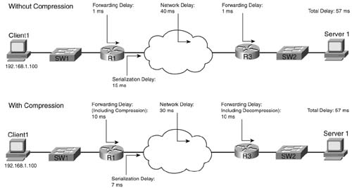
Table 8-1 outlines the major topics discussed in this chapter and the “Do I Know This Already?” quiz questions that correspond to those topics.
Caution The goal of self-assessment is to gauge your mastery of the topics in this chapter. If you do not know the answer to a question or are only partially sure of the answer, mark this question wrong for purposes of the self-assessment. Giving yourself credit for an answer you correctly guess skews your self-assessment results and might provide you with a false sense of security.
You can find the answers to the “Do I Know This Already?” quiz in Appendix A, “Answers to the ‘Do I Know This Already?’ Quizzes and Q&A Sections.” The suggested choices for your next step are as follows:
![]() 8 or less overall score—Read the entire chapter. This includes the “Foundation Topics,” the “Foundation Summary,” and the “Q&A” sections.
8 or less overall score—Read the entire chapter. This includes the “Foundation Topics,” the “Foundation Summary,” and the “Q&A” sections.
![]() 9 or 10 overall score—If you want more review on these topics, skip to the “Foundation Summary” section and then go to the “Q&A” section. Otherwise, move to the next chapter.
9 or 10 overall score—If you want more review on these topics, skip to the “Foundation Summary” section and then go to the “Q&A” section. Otherwise, move to the next chapter.
|
1. |
With CB RTP header compression, which of the following are compressed? a. RTP header b. TCP header d. UDP header e. Data |
|
2. |
With CB TCP header compression, which of the following are compressed? a. RTP header b. TCP header c. IP header d. UDP header e. Data |
|
3. |
With Layer 2 payload compression, which of the following could be compressed? a. RTP header b. TCP header c. IP header d. UDP header e. Data |
|
4. |
Which of the following Modular QoS Command-Line Interface (MQC) class subcommands enables CB RTP header compression? a. compression ip header rtp b. compression header ip rtp c. compression ip rtp d. compression header e. compression header ip |
|
5. |
In the show policy-map interface command output, with TCP or RTP header compression enabled, what does “efficiency improvement factor” mean? a. The number of bytes that would have been sent without compression, per second b. The ratio of bytes actually sent, over the number of bytes that would have been sent without compression c. The ratio of bytes that would have been sent without compression, over the number of bytes actually sent d. The compression ratio |
|
6. |
What fragment size, in bytes, should be used on a 256-Kbps link in order to ensure each fragment has less than or equal to 10 ms of serialization delay? a. 80 b. 160 c. 214 d. 240 e. 320 f. 480 |
|
7. |
What serialization delay, in milliseconds, would be experienced by a 160 byte fragment on a 64-kbps link? a. 5 b. 10 c. 15 d. 20 e. 25 f. 30 g. 35 h. 40 |
|
8. |
A router has MLP LFI configured on interface s0/0. The bandwidth 128 command is already configured on the multilink interface. Which of the following commands is used under a multilink interface in order to set the fragment size to 160 bytes? a. ppp multilink fragment-delay 10 b. ppp multilink fragment-size 160 c. ppp multilink interleave d. ppp fragment-delay 10 e. ppp fragment-size 160 |
|
9. |
A router has FRF.12 configured for all VC’s on interface s0/0. The bandwidth 128 command is already configured on the interface. Which of the following commands is used under the map-class frame-relay command in order to set the fragment size to 160 bytes? a. frame-relay fragment 10 b. frame-relay fragment 160 c. frame-relay traffic-shaping d. fragment 10 e. fragment 160 |
|
10. |
Which of the following commands list statistics about the number of fragments created with FRF.12? a. show queueing interface b. show fragments c. show interfaces d. show frame-relay fragment |
Compression involves mathematical algorithms that encode the original packet into a smaller string of bytes. After sending the smaller encoded string to the other end of a link, the compression algorithm on the other end of the link reverses the process, reverting the packet back to its original state.
Over the years, many mathematicians and computer scientists have developed new compression algorithms that behave better or worse under particular conditions. For instance, each algorithm takes some amount of computation, some memory, and they result in saving some number of bytes of data. In fact, you can compare compression algorithms by calculating the ratio of original number of bytes, divided by the compressed number of bytes—a value called the compression ratio. Depending on what is being compressed, the different compression algorithms have varying success with their compression ratios, and each uses different amounts of CPU and memory.
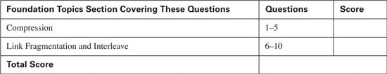
In Cisco routers, compression tools can be divided into two main categories: payload compression and header compression. Payload compression compresses headers and the user data, whereas header compression only compresses headers. As you might guess, payload compression can provide a larger compression ratio for larger packets with lots of user data in them, as compared to header compression tools. Conversely, header compression tools work well when the packets tend to be small, because headers comprise a large percentage of the packet. Figure 8-1 shows the fields compressed by payload compression, and by both types of header compression. (Note that the abbreviation DL stands for data link, representing the data-link header and trailer.)
Both types of compression tools require CPU cycles and memory. Payload compression algorithms tend to take a little more computation and memory, just based on the fact that they have more bytes to process, as seen in Figure 8-1. With any of the compression tools, however, the computation time required to perform the compression algorithm certainly adds delay to the packet. The bandwidth gained by compression must be more important to you than the delay added by compression processing, otherwise you should choose not to use compression at all!
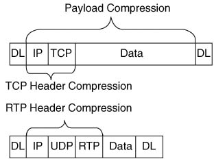
Figure 8-2 outlines an example showing the delays affected by compression. The compression and decompression algorithms take time, of course. However, serialization delay decreases, because the packets are now smaller. Queuing delay also decreases. In addition, on Frame Relay and ATM networks, the network delay decreases, because the network delay is affected by the amount of bits sent into the network.
This example uses contrived numbers to make the relevant points. The example assumes a 2:1 compression ratio, with a 1500-byte packet, and 768-kbps access links on both ends. The various delay components in the top half of the figure, without compression, add up to 57 ms. In the lower figure, with compression, the delay is still 57 ms. Because a 2:1 compression ratio was achieved, twice as much traffic can be sent without adding delay—it seems like an obvious choice to use compression! However, compression uses CPU and memory, and it is difficult to predict how compression will work on a particular router in a particular network. Compression requires that you try it, monitor CPU utilization, look at the compression ratios, and experiment before just deciding to add it to all routers over an entire network. In addition, although this example shows no increase in delay, in most cases, just turning on software compression will probably increase delay slightly, but still with the benefit of increasing the amount of traffic you can send over the link.
Compression hardware minimizes the delay added by compression algorithms. Cisco offers several types of hardware compression cards that reduce the delay taken to compress the packets. Cisco offers compression service adapters on 7200, 7300, 7400, 7500 routers, compression advanced integration modules (AIMs) on 3660 and 2600 routers, and compression network modules for 3620s and 3640s. On 7500s with Versatile Interface Processors (VIPs), the compression work can be distributed to the VIP cards, even if no compression adapters are installed. Thankfully, when the compression cards are installed and compression is configured, IOS assumes that you want the compression to occur on the card by default, requiring you to specifically configure software compression if you do not want to use the compression hardware for some reason.
Header compression algorithms take advantage of the fact that the headers are predictable. If you capture the frames sent across a link with a network analyzer, for instance, and look at IP packets from the same flow, you see that the IP headers do not change a lot, nor do the TCP headers, or UDP and RTP headers if RTP is used. Therefore, header compression can significantly reduce the size of the headers with a relatively small amount of computation. In fact, TCP header compression compresses the IP and TCP header (originally 40 bytes combined) down to between 3 and 5 bytes. Similarly, RTP header compression compresses the IP, UDP, and RTP headers (originally 40 bytes combined) to 2 to 4 bytes. (The variation in byte size for RTP headers results from the presence of a UDP checksum. Without the checksum, the RTP header is 2 bytes; with the checksum, the RTP header is 4 bytes.)
TCP header compression results in large compression ratios if the TCP packets are relatively small. For instance, with a 64-byte packet, with 40 of those being the IP and TCP headers, the compressed packet is between 27 and 29 bytes! That gives a compression ratio of 64/27, or about 2.37, which is pretty good for a compression algorithm that uses relatively little CPU. However, a 1500-byte packet with TCP header compression saves 35 to 37 bytes of the original 1500-byte packet, providing a compression ratio of 1500/1463, or about 1.03, a relatively insignificant savings in this case.
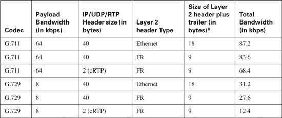
RTP header compression typically provides a good compression result for voice traffic, because VoIP tends always to use small packets. For instance, G.729 codecs in Cisco routers uses 20 bytes of data, preceded by 40 bytes of IP, UDP, and RTP headers. After compression, the headers are down to 4 bytes, and the packet size falls from 60 bytes to 24 bytes! Table 8-2 lists some of the overall VoIP bandwidth requirements, and the results of RTP header compression.
Cisco has supported TCP and RTP header compression natively in Cisco IOS Software for the last several major revisions. With Release 12.2(13)T, Cisco added IOS support for these two compression tools as Modular QoS Command-Line Interface (MQC)-based features. As a result, the configuration is painfully simple.
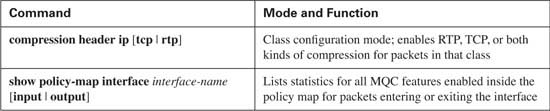
As with other MQC-based tools, you need to configure class maps and policy maps. And like the other MQC tools, there is one particular configuration command (compression header ip [tcp | rtp]) that enables the function, with this command added inside a class inside a policy map. The only slightly unusual task, as compared with other MQC-based tools, is that compression must be enabled on both sides of a point-to-point link or Frame Relay VC. Simply put, configuring compression tells a router to compress packets it will send, and to decompress packets it receives; if only one router on the end of a link or VC compresses and decompresses, the other router will become confused, and the packets will be discarded.
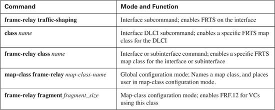
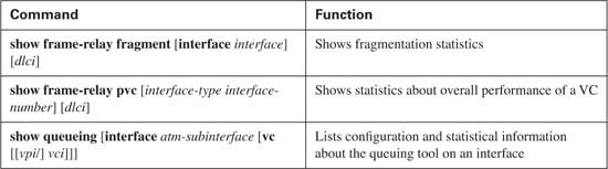
Table 8-3 lists the single configuration command for CB compression, along with a reference to the best show command to use with CB Compression.
You can see the power and simplicity of CB Compression with one single example network (see Figure 8-3) and configuration.
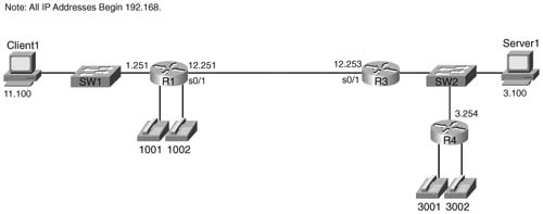
The network in Figure 8-3 has voice traffic, lots of email and web traffic, some Telnet traffic, and several other small TCP/IP applications. Because RTP can significantly reduce the amount of overhead, RTP header compression will be used. Also, TCP header compression is mostly beneficial with smaller TCP segments, so compressing Telnet traffic, and not compressing other traffic, makes good sense. So the choices made in this particular network are as follows:
![]() Use CB RTP Header Compression for voice traffic
Use CB RTP Header Compression for voice traffic
![]() Use CB TCP Header Compression for Telnet traffic
Use CB TCP Header Compression for Telnet traffic
![]() Do not compress other traffic
Do not compress other traffic
To test, a single G.729 VoIP call was made between phones off R4 and R1, along with a single Telnet connection from R4 to R1. Example 8-1 shows the configuration on R3.
Example 8-1 CB Header Compression on R3
Building configuration...
!
! Portions omitted for brevity
!
hostname R3
!
ip cef
!
match protocol telnet
class-map match-all voice-only
match protocol rtp audio
!
policy-map test-compress
class voice-only
priority 30
!
!
interface Serial0/1
ip address 192.168.4.3 255.255.255.0
clockrate 64000
!
R3#show policy-map interface s0/1
Serial0/1
Service-policy output: test-compress
Class-map: voice-only (match-all)
2880 packets, 184320 bytes
30 second offered rate 25000 bps, drop rate 0 bps
Match: protocol rtp audio
Queueing
Strict Priority
Output Queue: Conversation 264
Bandwidth 30 (kbps) Burst 750 (Bytes)
(total drops/bytes drops) 0/0
header ip rtp
UDP/RTP compression:
Sent: 2880 total, 2880 compressed,
106560 bytes saved, 66240 bytes sent
2.60 efficiency improvement factor
100% hit ratio, five minute miss rate 0 misses/sec, 0 max
rate 9000 bps
Class-map: telnet-only (match-all)
261 packets, 28399 bytes
30 second offered rate 0 bps, drop rate 0 bps
Match: protocol telnet
compress:
TCP compression:
Sent: 259 total, 242 compressed,
7877 bytes saved, 19390 bytes sent
1.40 efficiency improvement factor
99% hit ratio, five minute miss rate 0 misses/sec, 0 max
rate 0 bps
Queueing
Output Queue: Conversation 265
Bandwidth 20 (kbps) Max Threshold 64 (packets)
(pkts matched/bytes matched) 39/9832
(depth/total drops/no-buffer drops) 0/0/0
Class-map: class-default (match-any)
850 packets, 55734 bytes
30 second offered rate 0 bps, drop rate 0 bps
Match: any
First, examine the configuration for policy-map test-compress. Two classes are referencd, one for voice (class voice-only) and one for Telnet (class telnet-only). For voice, the compress header ip rtp command tells IOS to compress RTP flows that end up in this class. Similarly, the compress header ip tcp command tells IOS to use TCP header compression on flows that end up in class telnet-only.
Note If you omit the RTP and TCP keywords on the compress command, IOS performs both RTP and TCP header compression in that class.
Although not shown, a similar configuration is required on R1. Both routers on each end of the serial link need to enable RTP and TCP header compression for the exact same TCP and RTP flows. In reality, you will most likely use identical class maps on each router. The problem is that if one router tries to compress TCP packets, and the other does not expect to need to decompress the packets, then the TCP connection will fail. So, you essentially need the exact same policy map and classes on each side of the link when doing compression.
The output from the show policy-map interface serial 0/1 command lists statistics about the number of packets compressed, the bytes that would have been sent, and the number of bytes actually sent. By reverse engineering the counters, you can see the compression ratio and savings with CB RTP compression. For instance, the output claims a “2.6 Efficiency Improvement Factor” (for class voice-only), which is a fancy term for compression ratio. The counters state that the router sent and compressed 2880 total packets, with 106,560 bytes saved, and 66,240 bytes actually sent. Another way to interpret those numbers is to say that (106,560 + 66,240) bytes would have been sent without compression, and only 66,240 were sent with compression. So, the compression ratio would be (106,560 + 66,240) / 66,240, which is indeed a compression ratio of 2.6.
Another bit of interesting math with the counters can be seen by examining the number of bytes saved (106,560) versus the number of packets compressed (2880). The number of bytes saved per packet is 37, because 106,560/2880 is exactly 37. So, CB RTP compression is indeed compressing the 40-byte IP/UDP/RTP header into 3 bytes on average, saving 37 bytes per packet on average.
Both types of QoS tools covered in this chapter address bandwidth constraints to some degree. Compression tools directly attack bandwidth constraints by lowering the bandwidth required to forward packets. Link fragmentation and interleaving (LFI) tools directly lower delay by defeating a side effect of a small transmit clock speed, namely serialization delay.
A quick review of serialization delay should help you make more sense out of LFI tools. Serialization is the time required to send a frame over a physical link. If a link has a physical clock rate of x bps, it takes 1/x seconds to send a single bit. If a frame has y bits in it, it takes y/x seconds to serialize the frame. The faster the link, the lower the serialization delay. On a 56-kbps link, for example, it takes 1/56,000 of a second to send 1 bit. A 1500-byte frame (12,000 bits) takes 12,000/56,000 seconds to serialize, or roughly 214 ms.
When a router starts to send a frame out of an interface, it sends the complete frame. If a small, delay-sensitive frame needs to exit an interface, and the router has just begun to send a large frame, the small frame must wait until the whole large frame has been sent before the router will send the small, delay–sensitive frame. As seen in the preceding example, a 1500-byte frame takes 214 ms to serialize at 56 kbps, which is far too long for the small frame to wait if it is part of a VoIP stream.
LFI tools attack the serialization delay problem by ensuring that large packets do not delay smaller packets. It accomplishes this by dividing larger packets (fragmentation) and interleaving later-arriving smaller packets in between the fragments from the larger packet. The smaller, delay-sensitive interleaved packets, typically VoIP, are defined in your QoS policy. Figure 8-4 outlines the basic process.
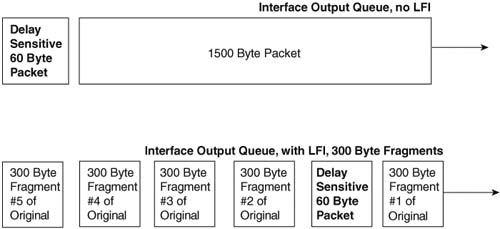
As shown in the upper queue in the figure, without LFI, the small 60-byte packet must wait for the full 1500-byte packet to be forwarded. In the lower queue, with LFI enabled, IOS can choose to let the smaller packet exit the interface ahead of some of the fragments of the larger packet.
Before examining LFI in more detail, you need to take a closer look at the terms “packet” and “frame.” In most cases in this book, these terms have been used interchangeably. However, it is important to realize what really gets placed into the queues, and what really gets fragmented, when discussing LFI tools.
First, we need a shared definition of what each of the two terms mean. Packet refers to the entity that flows through the network, including the Layer 3 header, all headers from layers above Layer 3, and the end-user data. Packets do not include the data-link (Layer 2) headers and trailers. Frames include the packet, as well as the data-link (Layer 2) header and trailer.
Queuing tools actually place frames into the queues. For instance, Weighted Fair Queuing (WFQ) on a PPP serial interface places PPP frames into the queues. Concerning queuing tools, the distinction does not really have much bearing on the choices you make. In addition, because most people tend to use the term “packet” more often, this book just uses packet when it does not matter whether you care about the packet or the frame.
LFI tools require you to think about what happens to the packet, and what happens to the frame. Consider Figure 8-5, which shows some of the details of an unfragmented frame, and a fragmented frame, using Frame Relay.
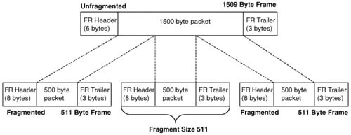
In the upper part of the figure, a 1500-byte packet has an extra 9 bytes of Frame Relay header and trailer added to it, to form a 1509-byte frame. In the lower part of the figure, the 1500-byte packet has been fragmented into three 500-byte fragments, and then placed into Frame Relay frames. It turns out that with FRF.12 LFI, an additional 2 bytes of header are needed to manage the fragments, so each of the three frames totals 511 bytes in length.
Technically, the fragment size used in the figure is 511 bytes, not 500. Most people would tend to think something like “the router fragmented the 1500-byte packet into three 500-byte fragments.” In reality, the router performs logic like in the following list:
![]() The router fragments the packet into smaller pieces.
The router fragments the packet into smaller pieces.
![]() The router adds the appropriate data-link headers and trailers, including any headers specifically needed for fragmentation support.
The router adds the appropriate data-link headers and trailers, including any headers specifically needed for fragmentation support.
![]() The length of the resulting frames (including data-link headers/trailers) does not exceed the fragmentation size configured.
The length of the resulting frames (including data-link headers/trailers) does not exceed the fragmentation size configured.
![]() The router adds these frames to the appropriate queue.
The router adds these frames to the appropriate queue.
So, the router fragments packets into smaller pieces, but the size of the pieces is determined by the fragment size, which is based on the frame size. Therefore, does LFI really fragment packets, or frames? Frankly, either term works. When you are choosing the size of the fragments, however, always remember that the fragment size determines the size of the frames, not the packets. Therefore, you should consider the length of the data-link headers and trailers when choosing the size of the fragments.
The core concept behind LFI, and its benefits, is very straightforward. The details, however, can be a little confusing, mainly because IOS LFI tools interact directly with IOS queuing tools. In addition, the two LFI tools covered on the Cisco QoS exam happen to behave differently as to how they interact with queuing tools. So to understand where LFI functions take place, you need to examine each tool specifically. This section covers multilink PPP LFI (MLP LFI), with Frame Relay fragmentation (FRF) covered in the next section of this chapter. Figure 8-6 depicts how MLP LFI works with a queuing tool on an interface.
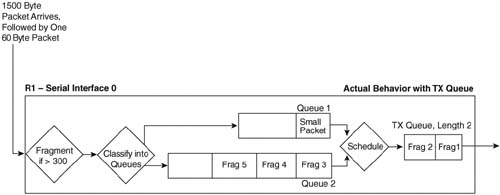
The figure outlines a lot of the detailed concepts behind LFI. In this example, a 1500-byte packet first arrives at R1, followed by a 60-byte packet. The fragmentation logic has been configured to fragment the frames down to a little more than 300 bytes, to make room for 300 bytes from the packet, and a little more for the data-link headers and trailers. After fragmentation, the queuing tool on the interface classifies the frames into their respective queues, which in this example happens to be two different queues. (The queuing tool’s classification step works exactly as described in Chapter 5, “Congestion Management.”)
Now look to the far right side of the figure. The TX Queue is shown, with a queue length of 2. In this example, an assumption has been made that the small packet arrived after IOS had placed the first two fragments of the large packet into the two available slots in the TX Queue, with the last three fragments being placed into Queue 2. The TX Queue is always absolutely a single FIFO queue, as described in Chapter 5. In other words, the small packet does not interrupt the router while it is in the middle of sending fragment 1, nor does the small packet have a chance to be sent before fragment 2, because fragment 2 is already in the TX Queue. The best behavior the small packet can hope for is to be the next packet placed onto the end of the TX Queue. Therefore, for now, the small packet has been placed into Queue 1.
Now look just to the left of the TX Queue, between the two interface output queues and the TX Queue. The term “schedule” reminds us that the queuing scheduler chooses the next packet to be moved from the output queues to the TX Queue (as described in Chapter 5). The queuing tool’s scheduler may decide to take the next packet from Queue 1 or Queue 2 — a decision totally based on the logic of the queuing tool.
Interleaving occurs when the queuing scheduler decides to service the queue that holds the small packet next, rather than the queue holding the next fragment of the large packet. If Low Latency Queuing (LLQ) has been configured, and Queue 1 is the low-latency queue, the scheduler takes the small packet next, meaning that the small packet would be interleaved between fragments of the larger packet. If the queuing tool was Custom Queuing (CQ), and the queuing scheduler were able to send more bytes from Queue 2 in this cycle, fragment 3 would be sent next.
How large should the fragments be to reduce serialization delay to an acceptable level? Well, the real answer lies in an analysis of the delay budgets for your network. From that analysis, you determine the maximum serialization delay you can have on each link.
The delay budget includes many delay components, such as queuing delay, propagation delay, shaping delay, network delay, and serialization delay. Based on that delay budget, you determine how much serialization delay you can afford on a particular link. Figure 8-7 depicts example delay values for various delay components.
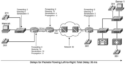
Now imagine that you need to configure R1 in the figure to use MLP LFI. You already know that you want a maximum serialization delay of 10 ms, and conveniently, MLP LFI enables you to configure a max-delay parameter. MLP LFI then calculates the fragment size, based on the following formula:
Max-delay * bandwidth
In this formula, bandwidth is the value configured on the bandwidth interface subcommand, and max-delay is the serialization delay configured on the ppp multilink fragment-delay command. For instance, R1 in Figure 8-7 shows a budget for 10 ms of serialization delay. On a 56-kbps link, a 10-ms max-delay would make the fragment size 56,000 * .01, or 560 bits, which is 70 bytes.
Cisco generally suggests a maximum serialization delay per link of 10-15 ms in multiservice networks. Because serialization delay becomes less than 10 ms for 1500-byte packets at link speeds greater than 768 kbps, Cisco recommends that LFI be considered on links with a 768-kbps clock rate and below.
Note Earlier Cisco courses, and some other Cisco documents, make the recommendation to set fragment sizes such that the fragements require 10 ms or less. The 10-15 ms recommendation is stated in the current Cisco QoS course.
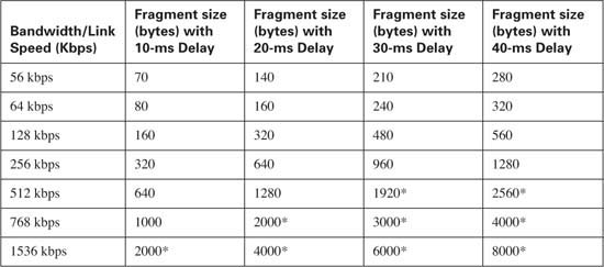
The math used to find the fragment size, based on the serialization delay and bandwidth, is pretty easy. For perspective, Table 8-4 summarizes the calculated fragment sizes based on the bandwidth and maximum delay.
Cisco IOS Software supports two flavors of Frame Relay LFI. The more popular option, FRF.12, is based on Frame Relay Forum Implementation Agreement 12, with the other option, FRF.11-C, being based on Frame Relay Forum Implementation Agreement 11, Annex C. FRF.12 applies to data VCs, and FRF.11-C applies to voice VCs. Because most Frame Relay VCs are data VCs, and because most service providers do not offer FRF.11 (VoFR) VCs, the exam focuses on FRF.12.
Note Another LFI feature, called multilink PPP over Frame Relay and ATM, also provides an option for LFI. This option is suited for environments that use Frame Relay/ATM internetworking and desire to run delay-sensitive applications such as VoIP on slow-speed WAN links.
FRF.12 varies greatly from MLP LFI in terms of how it works with queuing tools. To use FRF.12, IOS requires that Frame Relay Traffic Shaping (FRTS) also be used. The current QoS course does not focus on FRTS configuration as an end to itself. However, having read about and understood how CB Shaping works, you can learn about FRF.12 with only a little knowledge of FRTS.
Note Appendix B, “Additional QoS Reference Materials” (found on the book’s accompanying CD-ROM) contains FRTS concepts and configuration details, based on the first edition of this book.
Like CB Shaping, FRTS delays packets so that the Shaping rate is not exceeded. You configure the shaping rate, and a Bc value, and optionally a Be value if you want an excess burst capability. Like CB Shaping, FRTS delays the packets by putting them into a single FIFO queue, called a Shaping queue (assuming that no queuing tool has been configured). However, like CB Shaping, FRTS can be configured to use a Queuing tool. For example, Figure 8-8 shows FRTS configured to use LLQ to create four class queues for Shaping.
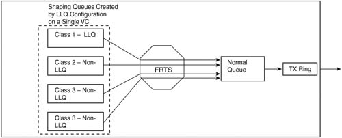
FRTS can apply queuing tools to shaping queues associated with each VC, as shown in the figure. Figure 8-8 shows a single LLQ, with three other CBWFQ class queues. As FRTS decides to allow additional packets to leave those queues each time interval, the packets are placed into a FIFO interface queue, because FRTS typically uses a single FIFO queue on the physical interface. IOS then moves the packets from the interface FIFO software queue into the TX Queue, and then out the interface.
When you add FRF.12 to FRTS, however, two interface FIFO output queues are created rather than the single FIFO queue. Figure 8-9 shows the two FIFO interface output queues, called Dual FIFO queues, with FTRS and FRF.12.
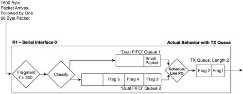
Figure 8-9 focuses on the interface software queues, ignoring the shaping queues. Just like in the figure that depicted MLP LFI, a 1500-byte packet arrives, followed by a 60-byte packet. The large packet is fragmented into five 300-byte packets, with the first two being placed into the TX Queue, and the last three ending up in one of the interface output queues. The small packet arrives next, and it is not fragmented, because it is less than 300 bytes in length. It is placed into the other Dual FIFO queue.
This two-queue Dual FIFO structure acts like the queuing tools described in Chapter 5 in many ways. It has classification logic that places packets into one queue or the other (more on that in a few paragraphs). It has a number of queues (always two), and it has particular behavior inside each queue (FIFO). It also performs scheduling between the two queues using an algorithm such as Priority Queuing’s (PQ) scheduling algorithm. Therefore, to understand what happens, you need to take a closer look at the classification logic and the scheduling algorithm applied to the Dual FIFO queues.
First, when a packet passes through the fragmentation step in Figure 8-9, if there are no packets in either Dual FIFO queue, and there is room in the TX Queue/TX Ring, the fragments get placed into the TX Ring/TX Queue until it is full. That’s why in Figure 8-9 the first two fragments of the large packet got placed into the 2-entry TX Queue. Then, when the TX Queue is full, packets are placed into one of the two Dual FIFO queues.
IOS schedules packets from the Dual FIFO interface queues into the interface TX Queue in a PQ-like fashion. The logic treats one of the two Dual FIFO queues like the PQ High queue, and the other like the PQ Normal queue. The scheduler always takes packets from the High queue first if one is available; otherwise, the scheduler takes a packet from the Normal queue. Just like PQ, the scheduler always checks the High queue for a packet before checking the Normal queue. Although IOS does not give a lot of information about the two Dual FIFO queues in show commands, one command (show queueing interface) does list counters for the High and Normal queues. (This book refers to these two queues as the High and Normal Dual FIFO queues, even though most other IOS documents and courses do not even name the two queues.)
Putting the classification logic together with the queue service logic makes one neat package. LFI wants to interleave the small packets between fragments of the larger packets. By classifying the unfragmented packets into the Dual-FIFO High queue, and the fragments into the Dual-FIFO Normal queue, the PQ-like queue service algorithm interleaves unfragmented packets in front of fragmented packets.
FRF.12 classifies packets into one of the Dual FIFO interface output queues based on the queuing configuration for the shaping queues on each VC. FRTS allows a large variety of queuing tools to be configured for the shaping queues. Two of these queuing tools, if enabled on the shaping Queue of a VC, cause packets to be placed in the High Dual FIFO queue on the physical interface. Figure 8-10 outlines the main concept.
Figure 8-10 Classification Between FRTS LLQ Shaping Queues and Interface Dual FIFO Queues with FRF.12
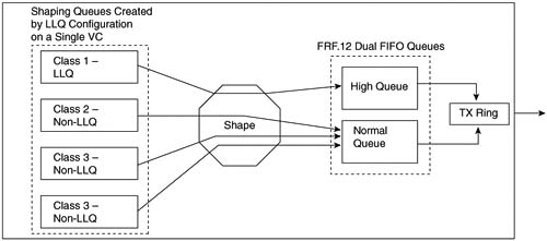
The figure depicts LLQ for the shaping queue on a single VC feeding into the interface Dual FIFO queues. The shaping logic remains unchanged, as does the LLQ logic for the shaping queues—in other words, with or without FRF.12 configured, the behavior of shaping acts the same. The only difference created by adding FRF.12 to FRTS comes when FRTS must decide which of the two interface Dual FIFO software queues to place the packet into after the shaper allows it to pass. (Without FRF.12, a single FIFO interface software queue exists, in which case classification logic is not needed.)
As shown in the figure, the only way a packet makes it to the High Dual FIFO queue is to have first been in the low-latency queue. In other words, FRF.12 determines which packets are interleaved based on which packets were placed into the low-latency queue in the shaping queue.
The classification logic and the scheduling logic make perfect sense if you consider the packets that need the minimal latency. When you purposefully configure LLQ for shaping queues, the class of packets you place into the low-latency queue must be the ones for which you want to minimize latency. FRF.12 should interleave those same packets to further reduce latency; therefore, FRF.12 just places those same packets into the Dual FIFO High queue.
Note Because the Dual FIFO queues created by FRF.12 essentially creates a high-priority queue appropriate for VoIP traffic, when you are using FRTS, Cisco also recommends configuring LFI on links that run at speeds greater than 768 kbps. However, you should configure the fragment size to something larger than the MTU — for instance, 1500 bytes. By doing so, no packets are actually fragmented, but VoIP packets can be placed in the high-priority queue in the Dual FIFO queuing system on the physical interface.
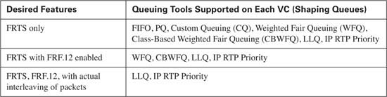
FRTS interaction and usage of queuing tools can be difficult to understand, let along trying to keep track of all the options. Interestingly, FRTS supports one set of queuing tools without FRF.12 enabled, and a subset with FRF.12 enabled, and with yet another subset of those (LLQ and IP RTP Priority) that actually interleave the packets. Table 8-5 summarizes the queuing tools and identifies when you can use them with FRTS and FRF.12.
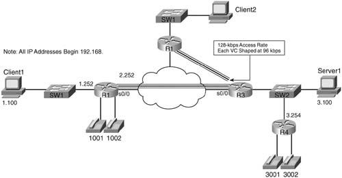
FRF.12 uses the same basic math as does MLP LFI to determine the fragment size—max-delay * bandwidth. But what do you use for bandwidth in the formula? CIR? Do you use the shaping or policing rate? Or the access rate, which is the clock rate used on the access link? Figure 8-11 shows a typical Frame Relay network that provides a backdrop from which to discuss which values to use.
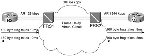
In most cases, you should choose to fragment based on the slower access rate on either end of a VC, which in this case is the 128-kbps access rate on R1. The reason you should use the lower of the two access rates becomes apparent only when you think of serialization delay inside the cloud, and in both directions. First, consider left-to-right flow in the network. To reduce serialization delay to 10 ms on a 128-kbps link, the fragment size should be set to 160 bytes (128,000 * .01 = 1280 bits). When R2 sends a packet, the serialization delay takes 10 ms. Moving from left to right, a full-sized fragment (160 bytes) sent from FRS1 to the Main router takes only 0.0008 seconds to serialize when passing over the T/1! Reversing the direction, a 160-byte fragment leaving router Main, going into the cloud, only takes 0.8 ms serialization delay, so you might be tempted to make the fragment size much larger for packets sent by router Main. When the packets get to FRS2, however, and need to cross the access link to R1, a small fragment size of 160 bytes gives you an advantage of low serialization delay. If you were to make the fragment size on the Main router a much larger size, the frame would experience a much larger serialization delay on the link from FRS1 to R1.
One common misconception is that fragmentation size should be based on the CIR of the VC, rather than on the access rate. Fragmentation attacks the problem of serialization delay, and serialization delay is based on how long it takes to encode the bits onto the physical interface, which in turn is determined by the physical clock rate on the interface. So, you should always base FRF.12 fragmentation sizes on the clock rate (access rate) of the slower of the two access links, not on CIR.
FRF.12 configuration does not let you set the maximum delay, as does MLP LFI. Instead, you configure the fragment size directly. When planning, you normally pick a maximum serialization delay for each link first. So before you can configure FRF.12, you need to calculate the fragmentation size. When you know the lower of the two access rates, and the maximum serialization delay desired, you can calculate the corresponding fragment size with the following formula:
Max-delay * bandwidth
For instance, to achieve 10-ms delay per fragment on a 128-kbps link, the fragment size would be:
.01 seconds * 128,000 bps, or 1280 bits (160 bytes)
Table 8-4, shown earlier in this section, lists some of the more common combinations of maximum delay and bandwidth, with the resulting fragment sizes.
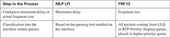
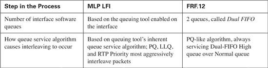
MLP LFI and FRF both accomplish the same general task of reducing serialization delay for some packets. As seen in this chapter, the methods used by each differ in how each tool takes advantage of queuing tools. Table 8-6 summarizes the core functions of MLP LFI versus FRF.12, particularly how they each interact with the available queuing tools.
Before you configure MLP LFI, think about why you would use MLP at all. If you have a point-to-point link, and need to perform LFI, you must migrate from your current Layer 2 protocol to MLP, to use MLP LFI. However, MLP itself has many benefits, and even a few brief thoughts about what MLP does will help you through some of the configuration tasks.
MLP enables you to have multiple parallel point-to-point links between a pair of devices, such as routers. The main motivation for MLP was to allow dial applications to continue adding additional switched WAN connections between the endpoints when more bandwidth was needed. For instance, maybe one dialed line was brought up, but when the utilization exceeded 60 percent, another line dialed, and then another, and so on.
MLP includes the inherent capability to load balance the traffic across the currently active lines, without causing reordering problems. To understand those concepts, consider Figure 8-12, with three parallel point-to-point links controlled by MLP.
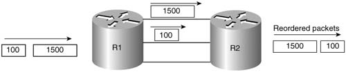
With three active links, MLP could reorder packets. If a 1500-byte packet arrives, for instance, immediately followed by a 100-byte packet, MLP might send the first packet over one link, and the next packet over the second link. Because the second packet is much smaller, its serialization delay will be much smaller. Assuming that both links speeds are equal, the 100-byte packet will arrive before the larger packet. Consequently, the 100-byte packet is forwarded first, before the 1500-byte packet. If both packets are part of the same flow, the endpoint computer may have to do more work to reorder the packets, which TCP could do if it is being used. However, some UDP-based applications could require that the out-of-order packets be re-sent, depending on the application. Over time, the three links will experience different utilization averages, depending on the random occurrence of traffic in the network.
MLP does not behave as shown in Figure 8-12. Instead, MLP, by its very nature, fragments packets. Figure 8-13 shows what really happens.
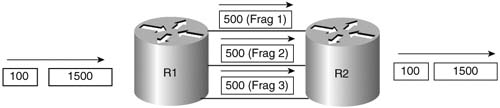
MLP always fragments PPP frames to load balance traffic equitably and to avoid out-of-order packets. Notice that the 1500-byte packet was fragmented into three 500-byte fragments, one for each link. By default, MLP fragments each packet into equal-sized fragments, one for each link. Suppose, for instance, that two links were active; the fragments would have been 750 bytes long. If four were active, each fragment would have been 375 bytes long. And yes, even the 100-byte packet would be fragmented, with one fragment being sent over each link.
The other point you should consider about basic MLP, before looking at MLP LFI configuration, is that the multiple links appear as one link from a Layer 3 perspective. In the figures, R1 and R2 each have one IP address that applies to all three links. To configure these details, most of the interface subcommands normally entered on the physical interface are configured somewhere else, and then applied to each physical interface that will comprise part of the same MLP bundle.
With those two basic MLP concepts in mind, you can now make more sense of the MLP LFI configuration. Tables 8-7 and 8-8 list the pertinent configuration and show commands, respectively, and are followed by some example configurations.
The first MLP LFI example shows a baseline configuration for MLP, without LFI. After this, the additional configuration commands for fragmentation, and then interleave, are added. Finally, the example ends with the addition of the ip rtp priority command, which enables one of the forms of queuing with a low-latency feature. (ip rtp priority simply puts all voice traffic in a PQ, and all other traffic is processed by the queuing tool enabled on the interface—in this case, WFQ. LLQ could have been used instead, with the same general result.) The explanation after the example explains how some traffic was interleaved (or not) at each step along the way.
The criteria for the configuration is as follows:
![]() Clock rate is 128 kbps on the point-to-point link.
Clock rate is 128 kbps on the point-to-point link.
![]() Fragment to 10-ms fragments.
Fragment to 10-ms fragments.
![]() Use RTP Priority.
Use RTP Priority.
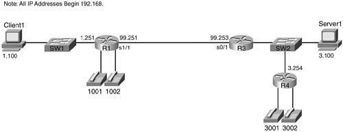
In the example, Client 1 downloads two to three web pages, each of which has two frames inside the page. Each web page uses two separate TCP connections to download two separate large JPG files. Client 1 also downloads a file using FTP get. In addition, a VoIP call is placed between extensions 3002 and 1002. Figure 8-14 shows the network used for the example, and Example 8-2 shows the configuration and some sample show commands.
Example 8-2 MLP LFI Configuration
! STEP 1 STEP 1 STEP 1 STEP 1 STEP 1 STEP 1 STEP 1 STEP 1 STEP 1 STEP 1 STEP 1 STEP 1
!
!
! Many lines omitted for brevity
!
username R1 password 0 me
!
bandwidth 128
ip address 192.168.99.253 255.255.255.0
no ip route-cache cef
load-interval 30
fair-queue
no cdp enable
ppp multilink
multilink-group 9
!
interface Serial0/1
bandwidth 128
no ip address
encapsulation ppp
no ip mroute-cache
load-interval 30
clockrate 128000
!
! STEP 2 STEP 2 STEP 2 STEP 2 STEP 2 STEP 2 STEP 2 STEP 2 STEP 2 STEP 2
!
! Adding Fragmentation for 10ms fragments. Added same command on R1 as well,
! No shown here for brevity.
!
R3#conf t
Enter configuration commands, one per line. End with CNTL/Z.
R3(config)#interface multilink 9
R3(config-if)#ppp multilink fragment-delay 10
R3(config-if)#^Z
R3#show interfaces multilink 9
Multilink9 is up, line protocol is up
Hardware is multilink group interface
Internet address is 192.168.99.253/24
MTU 1500 bytes, BW 128 Kbit, DLY 100000 usec,
reliability 255/255, txload 233/255, rxload 43/255
Encapsulation PPP, loopback not set
Keepalive set (10 sec)
DTR is pulsed for 2 seconds on reset
LCP Open, multilink Open
Open: IPCP
Last input 00:00:02, output never, output hang never
Last clearing of "show interface" counters 00:20:41
Input queue: 0/75/0/0 (size/max/drops/flushes); Total output drops: 1056
Output queue: 64/1000/64/1055 (size/max total/threshold/drops)
Reserved Conversations 0/0 (allocated/max allocated)
Available Bandwidth 96 kilobits/sec
30 second input rate 22000 bits/sec, 44 packets/sec
30 second output rate 117000 bits/sec, 48 packets/sec
4459 packets input, 273353 bytes, 0 no buffer
Received 0 broadcasts, 0 runts, 0 giants, 0 throttles
0 input errors, 0 CRC, 0 frame, 0 overrun, 0 ignored, 0 abort
62241 packets output, 5141980 bytes, 0 underruns
0 output errors, 0 collisions, 0 interface resets
0 output buffer failures, 0 output buffers swapped out
0 carrier transitions
! STEP 3 STEP 3 STEP 3 STEP 3 STEP 3 STEP 3 STEP 3 STEP 3 STEP 3 STEP 3
!
! Added Interleaving feature. Did same on R1, not shown here.
!
Enter configuration commands, one per line. End with CNTL/Z.
R3(config)#interface multilink 9
R3(config-if)#ppp multilink interleave
R3(config-if)#^Z
R3#show interfaces multilink 9
Multilink9 is up, line protocol is up
Hardware is multilink group interface
Internet address is 192.168.99.253/24
MTU 1500 bytes, BW 128 Kbit, DLY 100000 usec,
reliability 255/255, txload 227/255, rxload 29/255
Encapsulation PPP, loopback not set
Keepalive set (10 sec)
DTR is pulsed for 2 seconds on reset
LCP Open, multilink Open
Open: IPCP
Last input 00:00:00, output never, output hang never
Last clearing of "show interface" counters 00:22:00
Input queue: 0/75/0/0 (size/max/drops/flushes); Total output drops: 1406
Queueing strategy: weighted fair
Reserved Conversations 0/0 (allocated/max allocated)
Available Bandwidth 96 kilobits/sec
30 second input rate 15000 bits/sec, 30 packets/sec
30 second output rate 114000 bits/sec, 54 packets/sec
6386 packets input, 386857 bytes, 0 no buffer
Received 0 broadcasts, 0 runts, 0 giants, 0 throttles
0 input errors, 0 CRC, 0 frame, 0 overrun, 0 ignored, 0 abort
66702 packets output, 6267446 bytes, 0 underruns
0 output errors, 0 collisions, 0 interface resets
0 output buffer failures, 0 output buffers swapped out
0 carrier transitions
R3#
R3#show queue multilink 9
Input queue: 0/75/0/0 (size/max/drops/flushes); Total output drops: 1906
Queueing strategy: weighted fair
Output queue: 64/1000/64/1905/16500 (size/max total/threshold/drops/interleaves)
Conversations 5/11/32 (active/max active/max total)
Reserved Conversations 0/0 (allocated/max allocated)
Available Bandwidth 96 kilobits/sec
source: 192.168.3.100, destination: 192.168.1.100, id: 0xF513, ttl: 127,
source: 192.168.3.254, destination: 192.168.99.251, id: 0x08E5, ttl: 253,
!
! Lines omitted for brevity
!
! STEP 4 STEP 4 STEP 4 STEP 4 STEP 4 STEP 4 STEP 4 STEP 4 STEP 4 STEP 4
!
! Adding RTP Priority Queuing configuration next. Did same on R1.
!
R3#conf t
Enter configuration commands, one per line. End with CNTL/Z.
R3(config)#interface multilink 9
R3(config-if)#ip rtp priority 16384 16383 65
R3(config-if)#^Z
R3#
R3#show interfaces multilink 9
Multilink9 is up, line protocol is up
Hardware is multilink group interface
Internet address is 192.168.99.253/24
MTU 1500 bytes, BW 128 Kbit, DLY 100000 usec,
reliability 255/255, txload 231/255, rxload 41/255
Encapsulation PPP, loopback not set
Keepalive set (10 sec)
DTR is pulsed for 2 seconds on reset
LCP Open, multilink Open
Open: IPCP
Last input 00:00:03, output never, output hang never
Last clearing of "show interface" counters 00:23:36
Input queue: 0/75/0/0 (size/max/drops/flushes); Total output drops: 1784
Queueing strategy: weighted fair
Reserved Conversations 0/0 (allocated/max allocated)
Available Bandwidth 31 kilobits/sec
30 second input rate 21000 bits/sec, 43 packets/sec
30 second output rate 116000 bits/sec, 59 packets/sec
10217 packets input, 618117 bytes, 0 no buffer
Received 0 broadcasts, 0 runts, 0 giants, 0 throttles
0 input errors, 0 CRC, 0 frame, 0 overrun, 0 ignored, 0 abort
72195 packets output, 7661717 bytes, 0 underruns
0 output errors, 0 collisions, 0 interface resets
0 output buffer failures, 0 output buffers swapped out
R3#show queue multilink 9
Input queue: 0/75/0/0 (size/max/drops/flushes); Total output drops: 1784
Queueing strategy: weighted fair
Output queue: 18/1000/64/1783/6643 (size/max total/threshold/drops/interleaves)
Conversations 6/11/32 (active/max active/max total)
Reserved Conversations 0/0 (allocated/max allocated)
Available Bandwidth 31 kilobits/sec
source: 192.168.3.254, destination: 192.168.99.251, id: 0x08E5, ttl: 253,
source: 192.168.3.100, destination: 192.168.1.100, id: 0xED88, ttl: 127,
!
! Lines omitted for brevity
!
! STEP 5 STEP 5 STEP 5 STEP 5 STEP 5 STEP 5 STEP 5 STEP 5 STEP 5 STEP 5
!
R3#show running-config
!
! Lines omitted for brevity
!
username R1 password 0 me
!
bandwidth 128
ip address 192.168.99.253 255.255.255.0
no ip route-cache cef
load-interval 30
fair-queue
no cdp enable
ppp multilink
ppp multilink fragment-delay 10
ppp multilink interleave
multilink-group 9
ip rtp priority 16384 16383 65
interface Serial0/1
Cisco IOS Software enables you to use a couple of styles of configuration to configure MLP. This example shows the use of a virtual interface called a multilink interface. MLP needs to make more than one physical point-to-point link behave like a single link. To make that happen, IOS uses multilink interfaces to group together commands that normally would be applied to a physical interface. Each physical interface that is part of the same multilink group takes on the shared characteristics of the multilink interface. For instance, three parallel serial links in the same multilink group share a single IP address on one end of the link.
Example 8-2 is rather long. To help you find your way, the example includes comments lines with Step 1, Step 2, and so on. The following list explains these comments:
Step 1 In the example, multilink group 9 defines the interesting parameters in this example. Under the interface multilink 9 command, the IP address configuration (192.168.99.253), along with the bandwidth command, is listed. The multilink ppp command implies that this multilink group indeed uses multilink PPP. The multilink group 9 command tells IOS that this interface (multilink 9) is part of multilink group 9; this same command links each physical interface to the multilink group configuration. Now the interface configuration details that will be shared by all links in the same MLP bundle have been configured.
To add R3’s serial 0/1 interface to the MLP bundle, the multilink group 9 interface subcommand is added under serial 0/1. After the equivalent configuration has been added to R1, a single leased point-to-point serial link was up between R3 and R1, and each router was able to ping the other across the link.
Step 2 The example next shows the addition of the ppp multilink fragment-delay 10 command. Interestingly, this command does not enable fragmentation, but rather defines the maximum fragment size. Because the bandwidth was already set to 128, IOS calculates the fragment size as bandwidth * max-delay (in seconds), or 128,000 * .01, which results in a 1280 bit (160 byte) fragment size.
Before the ppp multilink fragment-delay 10 command was added, in this example, MLP did not fragment. If the ppp multilink fragment-delay command had not been added, and four links were active in the MLP bundle, MLP would fragment frames into four equal-sized fragments. If three links were active, each frame would be fragmented into three equal-sized fragments, and so on. With one active link, MLP does not actually fragment the frames until the ppp multilink fragment-delay command is added.
After adding the ppp multilink fragment-delay 10 command in the example, the voice-call quality did not improve. So far, the configuration asked for fragmentation, but not for interleaving. Without interleaving, the unfragmented packets still must wait on all the fragments of larger packets to be serialized. In the context of QoS, it seems rather silly not to automatically interleave the shorter, unfragmented frames. Remember, however, that MLP fragments frames to load balance across multiple links without running into the problems relating to out-of-order packets.
Step 3 To gain the QoS advantage of reducing serialization delay by interleaving packets, the ppp multilink interleave command is added to the configuration next. The show interfaces command that follows lists a (highlighted) line that now shows a counter for interleaved packets, with the counter indeed showing that some packets have been interleaved.
Now the example has added all the requirements for MLP LFI, and all seems well—but it is not! The voice quality is still barely tolerable, with long delay and many breaks in the speech. The voice quality still suffers because of the queuing tool, WFQ. Notice that the next command in the example, show queue multilink 9, lists a voice flow with some statistics highlighted for the voice flow. The command lists drops for the highlighted voice flow, which is making a large impact of voice quality. Although the voice packets that get serviced do get interleaved, causing the interleave counter in the show interfaces command to increment, the quality still suffers because of the queuing delay and drops.
Step 4 The best ways to prevent the drops is to enable Low Latency Queuing (LLQ) for the voice traffic. In this case, the configuration shows an older Queuing tool, IP RTP priority, which is enabled with the ip rtp priority 65 command. (However, LLQ is still recommended today for voice traffic.) After adding the ip rtp priority command, the show interfaces command still shows interleaves, which is good, but the show queue command does not show any drops for the voice flow. In fact, the voice-call quality improved significantly to the point that all New Jersey housewives would give the call a Mean Opinion Score of 5!
Step 5 The final configuration on R3 is listed at the end of the example for completeness.
The configuration of FRF.12 requires very little effort in itself. However, FRF.12 requires FRTS, and for the FRF.12 interleaving function to actually work, you need to enable IP RTP Priority or LLQ for the shaping queues on one or more VCs. Therefore, although the FRF.12 configuration details are brief, the related tools make the configuration a little longer.
The show commands related to FRF.12 give a fairly detailed view into what is actually happening with fragmentation and are covered as part of a couple of examples. Tables 8-9 and 8-10 list the configuration and show commands, respectively, and are followed by two FRF.12 examples.
The criteria for the configuration is as follows:
![]() Clock rate is 128 kbps on the access links on each end of the VC between R3 and R1.
Clock rate is 128 kbps on the access links on each end of the VC between R3 and R1.
![]() Fragment to 10-ms fragments.
Fragment to 10-ms fragments.
![]() Shape all traffic at a 64-kbps rate.
Shape all traffic at a 64-kbps rate.
![]() Configure Tc for 10ms.
Configure Tc for 10ms.
![]() Do not use a Be.
Do not use a Be.
![]() Enable the configuration on the subinterface.
Enable the configuration on the subinterface.
![]() Use WFQ for the Shaping Queues.
Use WFQ for the Shaping Queues.
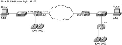
In the example, Client 1 downloads two to three web pages, each of which has two frames inside the page. Each web page uses two separate TCP connections to download two separate large JPG files. Client 1 also downloads a file using FTP get. In addition, a VoIP call is placed between extensions 3002 and 1002. Figure 8-15 shows the network used for the example, and Example 8-3 shows the configuration and some sample show commands.
Example 8-3 FRF.12 Configuration Sample
!
! Many lines omitted for brevity
!
interface Serial0/0
no ip address
encapsulation frame-relay
load-interval 30
clockrate 128000
!
! REFERENCE POINT 4!
bandwidth 128
!
! REFERENCE POINT 1
!
interface Serial0/0.1 point-to-point
description point-point subint global DLCI 103, connected via PVC to DLCI 101 (
ip address 192.168.2.253 255.255.255.0
!
! REFERENCE POINT 2
!
!
interface Serial0/0.2 point-to-point
description point-to-point subint connected to DLCI 102 (R2)
ip address 192.168.23.253 255.255.255.0
frame-relay interface-dlci 102
!
!
! Many lines omitted for brevity
!
!
! REFERENCE POINT 3
!
frame-relay traffic-rate 64000 640
no frame-relay adaptive-shaping
frame-relay fair-queue
frame-relay fragment 160
!
! REFERENCE POINT 5!
R3#show frame-relay fragment interface s 0/0.1 101
fragment size 160 fragment type end-to-end
reliability 255/255, txload 20/255, rxload 4/255
Encapsulation FRAME-RELAY, loopback not set
Keepalive set (10 sec)
LMI enq sent 14, LMI stat recvd 14, LMI upd recvd 0, DTE LMI up
LMI enq recvd 0, LMI stat sent 0, LMI upd sent 0
LMI DLCI 1023 LMI type is CISCO frame relay DTE
Broadcast queue 0/64, broadcasts sent/dropped 65/0, interface broadcasts 61
Last input 00:00:03, output 00:00:00, output hang never
Last clearing of "show interface" counters 00:02:20
Output queue 77/128, 176 drops; input queue 0/75, 0 drops
30 second input rate 26000 bits/sec, 51 packets/sec
30 second output rate 122000 bits/sec, 126 packets/sec
6599 packets input, 409250 bytes, 0 no buffer
Received 0 broadcasts,
0 runts, 0 giants, 0 throttles 0 input errors, 0 CRC, 0 frame, 0 overrun, 0 ignored, 0 abort
17824 packets output, 2169926 bytes, 0 underruns
0 output errors, 0 collisions, 0 interface resets
0 output buffer failures, 0 output buffers swapped out
0 carrier transitions
DCD=up DSR=up DTR=up RTS=up CTS=up
!
! REFERENCE POINT 9!
R3#show queueing interface s 0/0
high/0 medium/0 normal/16513 low/0
! Many lines omitted for brevity
!
Because this example is so long, and because FRTS is not covered in the main part of this book in this edition, the explanation that follows can be rather long. To help you correlate the upcoming explanations with the text in the example, the example contains reference numbers, which I’ll refer to inside the explanations.
First, a brief look at FRTS configuration is in order. (If you want more background, take a few minutes and look over the FRTS section in Appendix B.) At REFERENCE POINT 1, the frame-relay traffic-shaping command sits under physical interface s0/0. This command enables FRTS on every VC on the interface.
However, the details of the FRTS configruation—the shaping rate, the Bc, and so on—are defined at REFERENCE POINT 3. Notice the map-class frame-relay shape-all-64 command, which is followed by several subcommands. FRTS uses the map-class command to provide a configuration area where FRTS parameters can be configured. Those configuration parameters can be applied to one or more Frame Relay VCs using the frame-relay class shape-all-64 interface subcommand, shown at REFERENCE POINT 2.
In short, the frame-relay traffic-shaping command enables FRTS on the interface, the frame-relay class command points to a set of configuration parameters, and the map-class frame-relay command is the configuration area where the FRTS parameters are configured.
Take a look at the map class created at REFERENCE POINT 3 in the configuration. FRF is configured with the frame-relay fragment command inside a map-class command. In this case, the fragment size was set to 160 bytes, which at a bandwidth of 128 kbps implies 10 ms of serialization delay for the longest frame. (The bandwidth was set under the interface—look for REFERENCE POINT 4, which is above REFERENCE POINT 1, to find it.) So the configuration calls for a fragment size that makes each fragment require 10 ms of serialization delay.
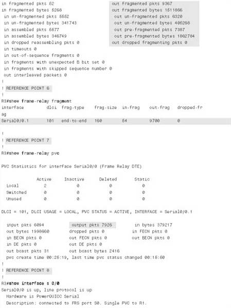
Now on to the show commands. The next command in the example (REFERENCE POINT 5), show frame-relay fragment int s 0/0.1 101, lists most of the detailed statistics about FRF behavior. The show command output lists counters for input and output packets and bytes as you might expect. In the example, 405,268 bytes have been sent in unfragmented frames, and 1,511,866 bytes in the fragmented frames, for a total of 1,917,134 bytes. It also lists a measurement of the number of output bytes that would have been sent had fragmentation not been used, as shown in the counters labeled “pre-fragmented.” The number of prefragmented bytes, listed as 1,862,784 in the command output, implies that R3 sent about 55,000 more bytes than it otherwise would have had to send had fragmentation not been used. This result is due to the added Frame Relay header and trailer overhead added to each fragment.
The shorter version of the same command, show frame-relay fragment (REFERENCE POINT 6), lists the basic configuration settings and just the counter of input and output fragmented packets.
The show frame-relay pvc command (REFERENCE POINT 7) lists statistics for each VC, but the counters represent values before fragmentation occurs. To see how the counters in this command and the show frame-relay fragment command compare, examine the highlighted value for packets sent, and the value of prefragmented output packets in the show frame-relay fragment command. The show frame-relay pvc command lists 7926 packets sent. The show frame-relay fragment command lists 7387 prefragmented packets sent, which is only a few less than what was seen in the show frame-relay pvc command that was typed just a few seconds later. Therefore, the show frame-relay pvc command counters are based on the packets before fragmentation.
Next, at REFERENCE POINT 8, the show interfaces serial 0/0 command lists a tidbit of insight into FRF operation. The highlighted portion of the command output lists the queuing method as Dual FIFO. As explained earlier, FRF causes two physical interface software queues to be used, as shown previously in Figure 8-9. The High queue gets PQ-like treatment, which is how FRF interleaves frames between the fragments in the other FRF output queue.
The final command in the example actually drives home two essential points (REFERENCE POINT 9). The show queueing interface serial 0/0 command lists information about queuing on interface serial 0/0, just as was seen many times in Chapter 5. In this case, it describes the queuing on the physical interface, which we call Dual FIFO. Notice, however, that the command lists the queuing method as “priority,” and it lists counters for four queues, named High, Medium, Normal, and Low. So although the queuing method is called Dual FIFO, it behaves like PQ, with only two queues in use.
You might have noticed that the only queue with nonzero counters in the show queueing command is the Normal queue. With FRF.12, the only way to get a packet into the High Dual-FIFO queue is to use IP RTP Priority or LLQ on an FRTS shaping queue. In Example 8-3, WFQ is used on the shaping queues (WFQ is enabled for FRTS with the map-class subcommand frame-relay fair-queue, near REFERENCE POINT 3 in the example.) Because WFQ does not have a PQ-like feature, none of the packets were interleaved into the Dual-FIFO High queue. In short, while the one important FRF.12 configuration command was used (frame-relay fragment), without a queuing tool to schedule packets into the Dual-FIFO high queue, it’s a waste of time, and actually causes unnecessary overhead.
To cause interleaving by enabling LLQ in this example, the map class would need to have a command like service-policy output do-llq, instead of frame-relay fair-queue. A policy-map do-llq would be needed, with configuration for LLQ inside it. By enabling LLQ in that map class, IOS would interleave packets exiting the LLQ into the Dual-FIFO high queue.
The next example uses LLQ to interleave the packets. Networks that need FRF.12 most often are those supporting voice traffic. These same networks need to use LLQ in the shaping queues to help reduce delay and jitter, and use FRF to reduce serialization delay. Shaping should also be tuned with a low Tc value, to reduce the delay waiting for the next shaping interval. The next example uses a class map called shape-all-96-shortTC, which includes FRF.12, LLQ, with shaping using a 10-ms Tc.
This next example also oversubscribes the access link from R3 to the FR cloud. When supporting voice, Cisco recommends to not oversubscribe an access link. However, many data-oriented Frame Relay designs purposefully oversubscribe the access links. Therefore, when the time comes to add VoIP traffic, increasing the CIRs on all the VCs may not be financially possible. This example uses two VCs, with each shaped at 96 kbps, with a 128-kbps access rate. Figure 8-16 outlines the network.
The criteria for the example is as follows:
![]() Clock rate is 128 kbps on all access links.
Clock rate is 128 kbps on all access links.
![]() Fragment to 10-ms fragments.
Fragment to 10-ms fragments.
![]() Shape all VCs at a 96-kbps rate.
Shape all VCs at a 96-kbps rate.
![]() Set Tc to 10 ms.
Set Tc to 10 ms.
![]() Do not use a Be.
Do not use a Be.
![]() Configure LLQ, with VoIP in the low-latency queue, and all other traffic in another queue.
Configure LLQ, with VoIP in the low-latency queue, and all other traffic in another queue.
In the example, Client 1 and Client 2 each download one web page, which has two frames inside the page. Each page download uses two separate TCP connections to download two separate large JPG files. Both PCs also download a file using FTP get. In addition, a VoIP call is placed between extensions 3002 and 1002. Figure 8-16 depicts the network used in the example. Example 8-4 shows the configuration and some sample show commands.
Example 8-4 Oversubscribed Access Link, with FRF.12, LLQ, and Tc = 10 ms
!
! Portions omitted for brevity
!
match ip rtp 16384 16383
!
!
policy-map voip-and-allelse
class voip-rtp priority 30
class class-default
fair-queue
interface Serial0/0
description connected to FRS port S0. Single PVC to R1.
no ip address
encapsulation frame-relay
load-interval 30
clockrate 128000
bandwidth 128
interface Serial0/0.1 point-to-point
description point-point subint global DLCI 103, connected via PVC to DLCI 101 (
ip address 192.168.2.253 255.255.255.0
!
interface Serial0/0.2 point-to-point
description point-to-point subint connected to DLCI 102 (R2)
ip address 192.168.23.253 255.255.255.0
!
no frame-relay adaptive-shaping
frame-relay cir 96000
frame-relay bc 960
service-policy output voip-and-allelse
frame-relay fragment 160
R3#show traffic-shape serial 0/0.1
Interface Se0/0.1
Access Target Byte Sustain Excess Interval Increment Adapt
VC List Rate Limit bits/int bits/int (ms) (bytes)
Active
101 96000 120 960 0 10 120 -
R3#show traffic-shape serial 0/0.2
Access Target Byte Sustain Excess Interval Increment Adapt
VC List Rate Limit bits/int bits/int (ms) (bytes) Active
102 96000 120 960 0 10 120 -
R3#show frame-relay fragment interface serial 0/0.1 101
fragment size 160 fragment type end-to-end
in fragmented pkts 14 out fragmented pkts 843
in fragmented bytes 1386 out fragmented bytes 135638
in un-fragmented pkts 596 out un-fragmented pkts 1607
in un-fragmented bytes 35967 out un-fragmented bytes 103064
in assembled pkts 603 out pre-fragmented pkts 1706
in assembled bytes 37283 out pre-fragmented bytes 234764
in dropped reassembling pkts 0 out dropped fragmenting pkts 0
in timeouts 0
in out-of-sequence fragments 0
in fragments with unexpected B bit set 0
in fragments with skipped sequence number 0
R3#show frame-relay fragment interface serial 0/0.2 102
fragment size 160 fragment type end-to-end
in fragmented pkts 0 out fragmented pkts 1541
in fragmented bytes 0 out fragmented bytes 235482
in un-fragmented pkts 285 out un-fragmented pkts 27
in un-fragmented bytes 12764 out un-fragmented bytes 1555
in assembled pkts 285 out pre-fragmented pkts 296
in assembled bytes 12764 out pre-fragmented bytes 227911
in dropped reassembling pkts 0 out dropped fragmenting pkts 0
in timeouts 0
in out-of-sequence fragments 0
in fragments with unexpected B bit set 0
in fragments with skipped sequence number 0
out interleaved packets 0
R3#show policy-map interface serial 0/0.2
Serial0/0.2: DLCI 102 -
Service-policy output: voip-and-allelse
Class-map: voip-rtp (match-all)
0 packets, 0 bytes
Weighted Fair Queueing
Output Queue: Conversation 24
Bandwidth 30 (kbps) Burst 750 (Bytes)
(pkts matched/bytes matched) 0/0
(total drops/bytes drops) 0/0
Class-map: class-default (match-any)
1440 packets, 1275806 bytes
30 second offered rate 55000 bps, drop rate 0 bps
Match: any
R3#show queueing interface serial 0/0
Interface Serial0/0 queueing strategy: priority
Output queue utilization (queue/count)
The FRF.12 configuration portion of the example is comprised again of a single command, frame-relay fragment 160, configured inside map-class frame-relay shape-all-96-shortTC. The rest of the configuration meets the other requirements stated before the example. The map class includes a setting of CIR to 96,000 bps, and a Bc of 960 bits, yielding a Tc value of 960/96,000, or 10 ms. The policy-map voip-and-allelse command defines LLQ for VoIP, with all other traffic being placed in the class-default queue. The service-policy output voip-and-allelse command under class-map frame-relay shape-all-96-shortTC enables LLQ for all VCs that use the class. FRTS is of course enabled on the physical interface, with the frame-relay class shape-all-96-shortTC subinterface command causing each of the two VCs to use the FRTS parameters in the map class, rather than the FRTS defaults.
Immediately following the configuration in the example, two show frame-relay traffic-shaping commands verify the settings made in the configuration. Both show a calculated Tc value of 10 ms, and a Bc of 960.
Next comes a pair of show frame-relay fragment interface commands, one for subinterface s 0/0.1, and one for serial interface 0/0.2. On serial 0/0.1, the last line of output points out that interleaves did occur. For interleaves to occur, at least a small amount of congestion must occur on the physical interface. With two VCs shaped at 96 kbps, and a 128-kbps access link, and plenty of generated traffic, some congestion did occur. Notice however that serial 0/0.2 does not show any interleaved packets. All the traffic generated going from R3 to R2 was FTP and HTTP traffic, neither of which gets classified into the low-latency queue. In the show policy-map interface serial 0/0.2 command that ends the example, for instance, notice that the counters show no packets have been in the low-latency queue. This example shows a perfect case where you have a VC (R3 to R2) that does not really need FRF for itself; FRF should be enabled, however, so that the small packets from other VCs can be interleaved.
The show queueing interface serial 0/0 command shows incrementing counters for both the High queue and the Normal queue. Because one voice call is using the VC from R3 to R1, the voice packets get placed into the R3-to-R1 VC’s low-latency queue, and then placed into the Dual FIFO High queue. (Interestingly, I did a few repetitive show queueing commands, once every 5 seconds, and saw the High queue counter increment about 250 packets per 5-second interval. With 20 ms of payload, each G.729 call sends 50 packets per second, so the counters reflected the fact that the voice packets from the low-latency queue were being placed into the Dual FIFO High queue.)
This last large section of this chapter, covering the configuration of MLP LFI and FRF.12, is relatively long, with some long configuration examples, and many configuration commands. However, if you boil away all the related discussion and examples, there are only a few configuration and show commands used specifically for MLP LFI and FRF.12. The rest of the commands relate to configuring the related features, namely MLP and FRTS.
To help you focus on the commands used specifically for LFI, Table 8-11 summarizes the commands and related information.

The “Foundation Summary” is a collection of tables and figures that provide a convenient review of many key concepts in this chapter. For those of you already comfortable with the topics in this chapter, this summary could help you recall a few details. For those of you who just read this chapter, this review should help solidify some key facts. For any of you doing your final prep before the exam, these tables and figures are a convenient way to review the day before the exam.
Figure 8-17 shows the fields compressed by payload compression, and by both types of header compression. (The abbreviation “DL” stands for data link, representing the data-link header and trailer.)
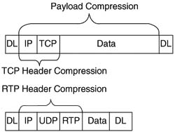
LFI tools attack the serialization delay problem by breaking the large packets into smaller pieces (fragmentation), and then sending the smaller frames ahead of most of the new fragments of the original large frame (interleaving). Figure 8-18 outlines the basic process.

Figure 8-19 depicts how MLP LFI works with a queuing tool on an interface.
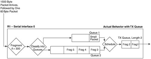
For perspective, Table 8-12 summarizes the calculated fragment sizes based on the bandwidth and maximum delay.
Table 8-12 Fragment Sizes Based on Bandwidth and Serialization Delay
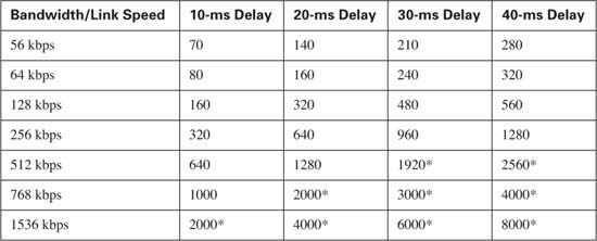
* Values over 1500 exceed the typical maximum transmit unit (MTU) size of an interface. Fragmentation of sizes larger than MTU does not result in any fragmentation.
Two of these queuing tools, if enabled on the shaping queue of a VC, cause packets to be placed in the High Dual FIFO queue on the physical interface. Figure 8-20 outlines the main concept.
Figure 8-20 Classification Between FRTS LLQ Shaping Queues and Interface Dual FIFO Queues with FRF.12

MLP, by its very nature, fragments packets. Figure 8-21 shows what really happens.
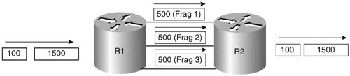
To help you focus on the commands used specifically for LFI, Table 8-13 summarizes the commands and related information.
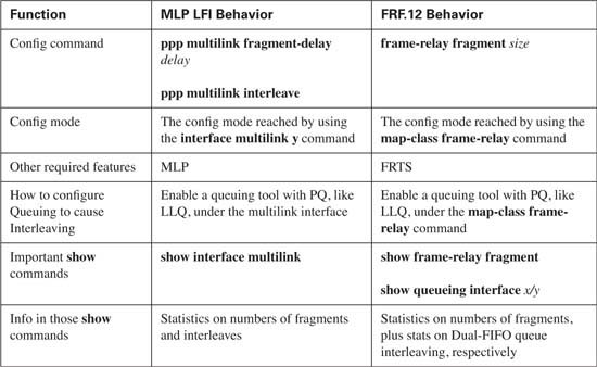
As mentioned in the Introduction, you have two choices for review questions. The questions that follow next give you a more difficult challenge than the exam itself by using an open-ended question format. By reviewing now with this more difficult question format, you can exercise your memory better, and prove your conceptual and factual knowledge of this chapter. You can find the answers to these questions in Appendix A.
The second option for practice questions is to use the CD-ROM included with this book. It includes a testing engine and more than 200 multiple-choice questions. You should use this CD-ROM nearer to the end of your preparation, for practice with the actual exam format.
|
1. |
Describe what is compressed, and what is not compressed, when using payload compression. Be as specific as possible regarding headers and data. |
|
2. |
Describe what is compressed, and what is not compressed, when using TCP header compression. Be as specific as possible regarding headers and data. |
|
3. |
Describe what is compressed, and what is not compressed, when using RTP header compression. Be as specific as possible regarding headers and data. |
|
4. |
Suppose a packet is sent across a network with no compression. Later, a packet of the exact same size and contents crosses the network, but payload compression is used on the one serial link in the network. Describe the difference in bandwidth and delay in the network between these two packets. |
|
5. |
How much bandwidth should a G.729 call require over Frame Relay, and how much should be required with cRTP? |
|
6. |
When TCP header compression is used, what is the range of sizes of the part of the frame that can be compressed, and what is the range of sizes for this field of the frame after compression? |
|
7. |
When RTP header compression is used, what is the range of sizes of the part of the frame that can be compressed, and what is the range of sizes for this field of the frame after compression? The next several questions refer to the following configuration snippet. !
hostname R1 ! ip cef ! class-map match-all class1 match protocol telnet
class-map match-all class2 match protocol rtp audio ! ! policy-map test-compress class class2 compression header ip class class1 compression header ip tcp bandwidth 20 ! ! interface Serial0/1 ip address 10.1.1.1 255.255.255.0 service-policy output test-compress load-interval 30 clockrate 64000 ! ! hostname R2 ! ip cef ! policy-map catch-all class class-default compression header ip ! ! interface Serial0/1 ip address 10.1.1.1 255.255.255.0 service-policy output catch-all load-interval 30 |
|
8. |
The configuration snippet shows the configuration on two routers, R1 and R2, on the serial interfaces attached to a common serial link. Will VoIP RTP sessions be compressed, or even work at all? Explain why or why not in relation to what has been configured on the two routers. |
|
9. |
The configuration snippet shows the configuration on two routers, R1 and R2, on the serial interfaces attached to a common serial link. Will telnet connections be compressed, or even work at all? Explain why or why not in relation to what has been configured on the two routers. |
|
10. |
The configuration snippet shows the configuration on two routers, R1 and R2, on the serial interfaces attached to a common serial link. Will web TCP connections be compressed, or even work at all? Explain why or why not in relation to what has been configured on the two routers. |
|
11. |
Without creating all the exact configuration commands, generally describe the types of changes to the configuration on R2 that would be required in order to ensure that none of the flows would fail due to one router wanting to compress, and the other one not wanting to compress. |
|
12. |
List the words represented by the abbreviation LFI. |
|
13. |
Describe the main motivation for LFI tools in relation to the support of data, voice, and video traffic. |
|
14. |
To achieve a 20-ms serialization delay on a 128-kbps link, how long can the fragments be? |
|
15. |
To achieve a 10-ms serialization delay on a 64-kbps link, how long can the fragments be? |
|
16. |
To achieve a 10-ms serialization delay on a 56-kbps link, how long can the fragments be? |
|
17. |
To achieve a 30-ms serialization delay on a 128-kbps link, how long can the fragments be? |
|
18. |
Suppose that a 1500-byte packet exits a 56-kbps serial interface, and LFI is not used. How long is the serialization delay? |
|
19. |
Which queuing tools can you enable directly on a serial interface when using multilink Point-to-Point Protocol with link fragmentation and interleaving (MLP LFI), in order to interleave packets? |
|
20. |
Which queuing tools can you enable with FRTS in order to actually interleave the traffic? |
|
21. |
Explain the scheduling logic used by MLP LFI to determine which packets can be interleaved in front of fragments of other packets. |
|
22. |
Suppose a 1500-byte packet arrives and needs to be sent over an MLP bundle that has two active links. LFI has not been configured. Which link does the packet flow across to achieve MLP load balancing? |
|
23. |
What command can you use to determine the fragment size used for MLP LFI? What is the only parameter of the command? |
|
24. |
What command enables the interleaving feature of MLP LFI? |
|
25. |
What commands list counters for the number of interleaved packets using MLP LFI? |
|
26. |
What other QoS feature for Frame Relay must you enable when you also configure FRF.12? |
|
27. |
What command enables FRF and sets the fragment size? |
|
28. |
What command lists counters for the numbers of packets and bytes that were fragmented and unfragmented by FRF.12? |
|
29. |
What command lists counters for the numbers of packets and bytes that would have been sent if FRF.12 fragmentation had not been performed? |
|
30. |
What command lists counters for the number of packets that end up in the High and Normal Dual-FIFO siftware queues, when using FRF.12? |