
Chapter 15
High Availability and Disaster Recovery
High availability is a system-design protocol that guarantees a certain amount of operational uptime during a given period. The design attempts to minimize unplanned downtime—the time users are unable to access resources. In almost all cases, high availability is provided through the implementation of duplicate equipment (multiple servers, multiple NICs, etc.). Organizations that serve critical functions obviously need this; after all, you really don't want to rush to a hospital ER only to find that they can't treat you because their network is down!
Fault tolerance means that even if one component fails, you won't lose access to the resource it provides. To implement fault tolerance, you need to employ multiple devices or connections that all provide a way to access the same resource(s).
A familiar form of fault tolerance is configuring an additional hard drive to be a mirror image of the original so that if either one fails, there's still a copy of the data available to you. In networking, fault tolerance means that you have multiple paths from one point to another. What's really cool is that fault-tolerant connections can be configured to be available either on a standby basis only or all the time if you intend to use them as part of a load-balancing system.
In this chapter you will learn about redundancy concepts, fault tolerance, and the process of disaster recovery.
Load Balancing
Load balancing refers to a technique used to spread work out to multiple computers, network links, or other devices.
Using load balancing, you can provide an active/passive server cluster in which only one server is active and handling requests. For example, your favorite Internet site might actually consist of 20 servers that all appear to be the same exact site because that site's owner wants to ensure that its users always experience quick access. You can accomplish this on a network by installing multiple, redundant links to ensure that network traffic is spread across several paths and to maximize the bandwidth on each link.
Think of this as similar to having two or more different freeways that will both get you to your destination equally well—if one is really busy, just take the other one.
Multipathing
Multipathing is the process of configuring multiple network connections between a system and its storage device. The idea behind multipathing is to provide a backup path in case the preferred connection goes down. For example, a SCSI hard disk drive may connect to two SCSI controllers on the same computer, or a disk may connect to two Fibre Channel ports.
The ease with which multipathing can be set up in a virtual environment is one of the advantages a virtual environment provides. A multipath configuration is shown in Figure 15.1.
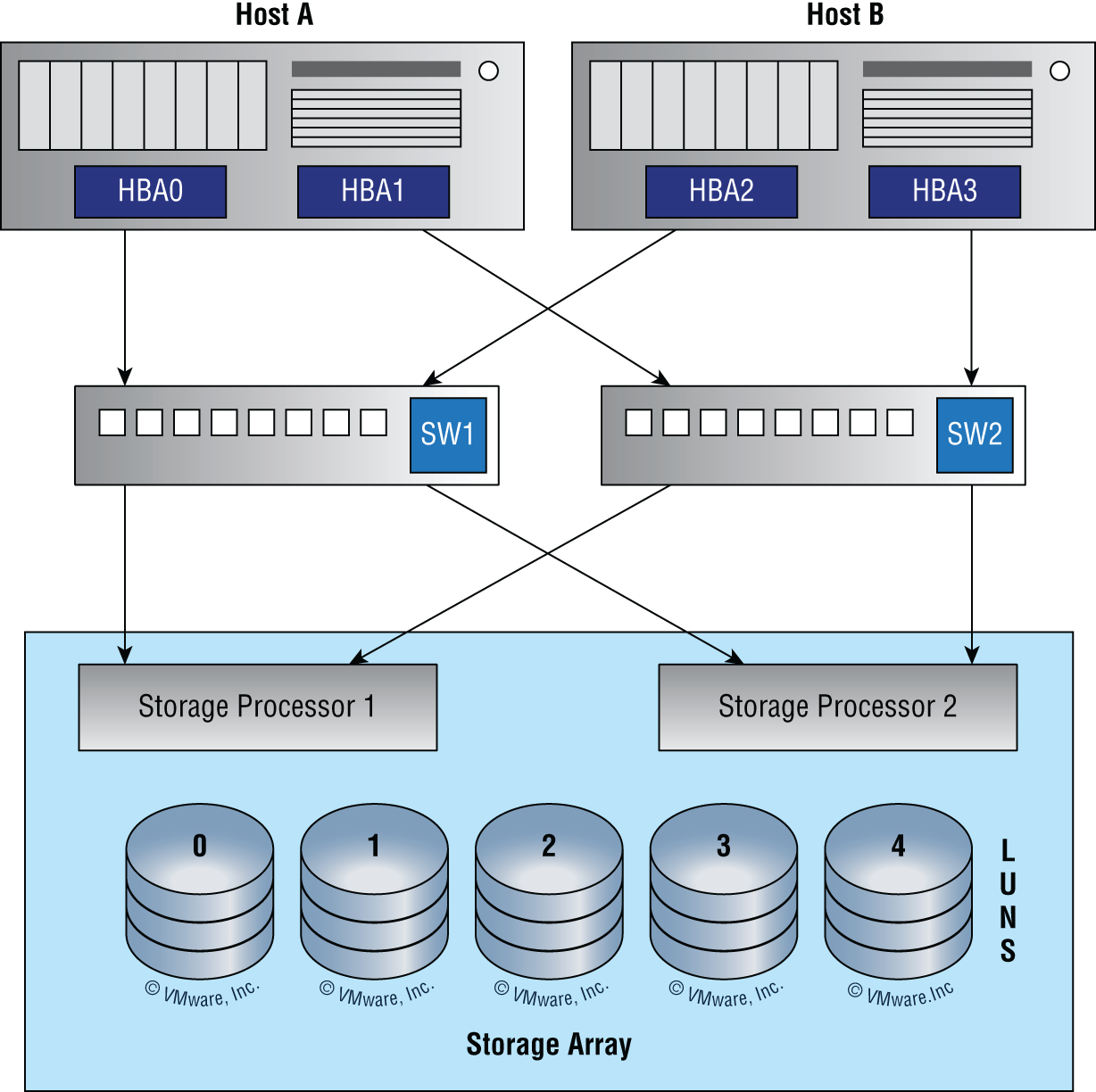
FIGURE 15.1 Multipathing
Both Host A and Host B have multiple host bus adapters (NICs) and multiple connections through multiple switches and are mapped to multiple storage processors as well. This is a highly fault-tolerant arrangement that can survive an HBA failure, a path failure, a switch failure, and a storage processor failure.
Network Interface Card (NIC) Teaming
NIC teaming allows multiple network interfaces to be placed into a team for the purposes of bandwidth aggregation and/or traffic failover to prevent connectivity loss in the event of a network component failure. The cards can be set to active/active state, where both cards are load balancing, or active/passive, where one card is on standby in case the primary card fails. Most of the time, the NIC team will use a multicast address to send and receive data, but it can also use a broadcast address so all cards receive the data at the same time.
This can be done with a single switch or multiple switches. Figure 15.2 shows what is called static teaming, where a single switch is in use. This would provide failover only for the connection but would not protect against a switch failure.

FIGURE 15.2 Static teaming
A more redundant arrangement is shown in Figure 15.3, where a switch-independent setup is in use. This provides fault tolerance for both switches and connections.

FIGURE 15.3 Switch independent setup
Redundant Hardware/Clusters
By now it must be clear that redundancy is a good thing. While this concept can be applied to network connections, it can also be applied to hardware components and even complete servers. In the following sections, you'll learn how this concept is applied to severs and infrastructure devices.
Switches
As you saw in the last section, multiple switches can be deployed to provide for failover if a switch fails. When this is done, it sometimes creates what is called a switching loop. Luckily, as you learned in Chapter 11, there is a protocol called Spanning Tree Protocol that can prevent these loops from forming. There are two forms of switch redundancy, switch stacking and switch clusters.
Switch Stacking
Switch stacking is the process of connecting multiple switches together (usually in a stack) and managing them as a single switch. Figure 15.4 shows a typical configuration.

FIGURE 15.4 Switch stacking
The stack members work together as a unified system. Layer 2 and layer 3 protocols present the entire switch stack as a single entity to the network.
A switch stack always has one active switch and one standby switch. If the active switch becomes unavailable, the standby switch assumes the role of the active switch and continues to keep the stack operational.
The active switch controls the operation of the switch stack and is the single point of stack-wide management.
Hard to believe that Cisco is using switch stacking to start its “Evolution of Intelligent Networks” objectives since switch stacking has been around since the word cloud meant 4/20 in my home town of Boulder, but I digress.
A typical access closet contains one or more access switches placed next to each other in the same rack and uses high-speed redundant links with copper, or more typically fiber, to the distribution layer switches.
Here are three big drawbacks to a typical switch topology:
- Overhead of management.
- STP will block half of the uplinks.
- No direct communication between switches.
Cisco StackWise technology connects switches that are mounted in the same rack together so they basically become one larger switch. By doing this, you clearly get more access ports for each closet while avoiding the cost of upgrading to a bigger switch. So you're adding ports as you grow your company instead of front loading the investment into a pricier, larger switch all at once. And since these stacks are managed as a single unit, it reduces the management in your network.
All switches in a stack share configuration and routing information so you can easily add or remove switches at any time without disrupting your network or affecting its performance. Figure 15.4 shows a typical switch stack.
To create a StackWise unit, you combine switches into a single, logical unit using special stack interconnect cables as shown in Figure 15.4. This creates a bidirectional closed-loop path in the stack.
Here are some other features of StackWise:
- Any changes to the network topology or routing information are updated continuously through the stack interconnect.
- A master switch manages the stack as a single unit. The master switch is elected from one of the stack member switches.
- You can join up to nine separate switches in a stack.
- Each stack of switches has only a single IP address and the stack is managed as a single object. You'll use this single IP address for all the management of the stack, including fault detection, VLAN database updates, security, and QoS controls. Each stack has only one configuration file, which is distributed to each switch in the StackWise.
- Using Cisco StackWise will produce some management overhead, but at the same time, multiple switches in a stack can create an EtherChannel connection, eliminating the need for STP.
Here's a list of the benefits to using StackWise technology:
- StackWise provides a method to join multiple physical switches into a single logical switching unit.
- Switches are united by special interconnect cables.
- The master switch is elected.
- The stack is managed as a single object and has a single management IP address.
- It reduces management overhead.
- STP is no longer needed if you use EtherChannel.
- Up to 9 switches can be in a StackWise unit.
One more very cool thing—when you add a new switch to the stack, the master switch automatically configures the unit with the currently running IOS image as well as the configuration of the stack. So you don't have to do anything to bring up the switch before its ready to operate. Nice!
Switch Clustering
A switch cluster is another option. This is a set of connected and cluster-capable switches that are managed as a single entity without interconnecting stack cables. This is possible by using Cluster Management Protocol (CMP). The switches in the cluster use the switch clustering technology so that you can configure and troubleshoot a group of different switch platforms through a single IP address. In those switches, one switch plays the role of cluster command switch, and the other switches are cluster member switches that are managed by the command switch. Figure 15.5 shows a switch cluster. Notice that the cluster is managed by using the CMP address of the cluster commander.

FIGURE 15.5 Switch cluster
Routers
Routers can also be set up in a redundant fashion. When we provide router redundancy, we call it providing first-hop redundancy since the router will be the first hop from any system to get to a destination. To accomplish first-hop redundancy requires an FHRP protocol.
First-hop redundancy protocols (FHRPs) work by giving you a way to configure more than one physical router to appear as if they were only a single logical one. This makes client configuration and communication easier because you can simply configure a single default gateway and the host machine can use its standard protocols to communicate. First hop is a reference to the default router being the first router, or first router hop, through which a packet must pass.
So how does a redundancy protocol accomplish this? The protocols I'm going to describe to you do this basically by presenting a virtual router to all of the clients. The virtual router has its own IP and MAC addresses. The virtual IP address is the address that's configured on each of the host machines as the default gateway. The virtual MAC address is the address that will be returned when an ARP request is sent by a host. The hosts don't know or care which physical router is actually forwarding the traffic, as you can see in Figure 15.6.

FIGURE 15.6 FHRPs use a virtual router with a virtual IP address and virtual MAC address.
It's the responsibility of the redundancy protocol to decide which physical router will actively forward traffic and which one will be placed in standby in case the active router fails. Even if the active router fails, the transition to the standby router will be transparent to the hosts because the virtual router, identified by the virtual IP and MAC addresses, is now used by the standby router. The hosts never change default gateway information, so traffic keeps flowing.
Fault-tolerant solutions provide continued operation in the event of a device failure, and load-balancing solutions distribute the workload over multiple devices. Later in this chapter you will learn about the two most common FHRPs.
Firewalls
Firewalls can also be clustered, and some can also use FHRPs. A firewall cluster is a group of firewall nodes that work as a single logical entity to share the load of traffic processing and provide redundancy. Clustering guarantees the availability of network services to the users.
Cisco Adaptive Security Appliance (ASA) and Cisco Firepower next-generation firewall (NGFW) clustering allow you to group multiple ASA nodes together as a single logical device to provide high availability and scalability. The two main clustering options discussed in this chapter are active/standby and active/active. In both cases, the firewall cluster looks like a single logical device (a single MAC/IP address) to the network.
Later in this chapter you will learn more about active/active and active/standby operations.
Facilities and Infrastructure Support
When infrastructure equipment is purchased and deployed, the ultimate success of the deployment can depend on selecting the proper equipment, determining its proper location in the facility, and installing it correctly. Let's look at some common data center and server room equipment and a few best practices for managing these facilities.
Uninterruptible Power Supply (UPS)
One risk that all organizations should prepare for is the loss of power. All infrastructure systems should be connected to uninterruptible power supplies (UPSs). These devices can immediately supply power from a battery backup when a loss of power is detected. You should keep in mind, however, that these devices are not designed as a long-term solution. They are designed to provide power long enough for you to either shut the system down gracefully or turn on a power generator. In scenarios where long-term backup power is called for, a gas-powered generator should be installed.
Power Distribution Units (PDUs)
Power distribution units (PDUs) simply provide a means of distributing power from the input to a plurality of outlets. Intelligent PDUs normally have an intelligence module that allows for remote management of power metering information, power outlet on/off control, and/or alarms. Some advanced PDUs allow users to manage external sensors such as temperature, humidity, and airflow.
While these can be as simple as a power strip, in data centers, larger PDUs are needed to power multiple server cabinets. Each server cabinet or row of cabinets may require multiple high current circuits, possibly from different phases of incoming power or different UPSs. Stand-alone cabinet PDUs are self-contained units that include main circuit breakers, individual circuit breakers, and power monitoring panels. Figure 15.7 shows a standard rack-mounted PDU.

FIGURE 15.7 Rack-mounted PDU
Generator
As you learned earlier in this chapter, a UPS is not designed for long-term power supply. The battery will run out. This should be supplemented with a backup generator if more than an hour or so of backup is required. The amount of backup time supplied by a generator is limited only by the amount of fuel you keep on hand.
HVAC
The heating and air-conditioning systems must support the massive amounts of computing equipment deployed by most enterprises. Computing equipment and infrastructure devices like routers and switches do not like the following conditions:
- Heat. Excessive heat causes reboots and crashes.
- High humidity. It causes corrosion problems with connections.
- Low humidity. Dry conditions encourage static electricity, which can damage equipment.
The American Society of Heating, Refrigerating and Air-Conditioning Engineers (ASHRAE) publishes standards for indoor air quality and humidity. Their latest recommendations are as follows:
- A class A1 data center
- Can range in temperature from 59°F to 89.6°F
- Can range in relative humidity from 20 percent to 80 percent
Also keep in mind:
- At 175°F, damage starts occurring to computers and peripherals.
- At 350°F, damage starts occurring to paper products.
Fire Suppression
While fire extinguishers are important and should be placed throughout a facility, when large numbers of computing devices are present, it is worth the money to protect them with a fire-suppression system. The following types of systems exist:
- Wet pipe systems use water contained in pipes to extinguish the fire.
- Dry pipe systems hold the water in a holding tank instead of in the pipes.
- Preaction systems operate like a dry pipe system except that the sprinkler head holds a thermal-fusible link that must melt before the water is released.
- Deluge systems allow large amounts of water to be released into the room, which obviously makes this not a good choice where computing equipment will be located.
At one time, fire suppression systems used halon gas, which works well by suppressing combustion through a chemical reaction. However, the US Environmental Protection Agency banned halon manufacturing in 1994 as it has been found to damage the ozone layer.
The EPA has approved the following replacements for halon:
- Water
- Argon
- NAF-S-III
Another fire suppression system that can be used in computer rooms that will not damage computers and is safe for humans is FM-200.
Redundancy and High Availability (HA) Concepts
All organizations should identify and analyze the risks they face. This is called risk management. In the following sections, you'll find a survey of topics that all relate in some way to addressing risks that can be mitigated with redundancy and high availability techniques.
Recovery Sites
Although a secondary site that is identical in every way to the main site with data kept synchronized up to the minute would be ideal, the cost cannot be justified for most organizations. Cost-benefit analysis must be applied to every business issue, even disaster recovery. Thankfully, not all secondary sites are created equally. They can vary in functionality and cost. We're going to explore four types of sites: cold sites, warm sites, hot sites, and cloud sites.
Cold Site
A cold site is a leased facility that contains only electrical and communications wiring, air conditioning, plumbing, and raised flooring. No communications equipment, networking hardware, or computers are installed at a cold site until it is necessary to bring the site to full operation. For this reason, a cold site takes much longer to restore than a hot or warm site.
A cold site provides the slowest recovery, but it is the least expensive to maintain. It is also the most difficult to test.
Warm Site
The restoration time and cost of a warm site is somewhere between that of a hot site and a cold site. It is the most widely implemented alternate leased location. Although it is easier to test a warm site than a cold site, a warm site requires much more effort for testing than a hot site.
A warm site is a leased facility that contains electrical and communications wiring, full utilities, and networking equipment. In most cases, the only thing that needs to be restored is the software and the data. A warm site takes longer to restore than a hot site but less than a cold site.
Hot Site
A hot site is a leased facility that contains all the resources needed for full operation. This environment includes computers, raised flooring, full utilities, electrical and communications wiring, networking equipment, and uninterruptible power supplies (UPSs). The only resource that must be restored at a hot site is the organization's data, usually only partially. It should only take a few minutes to bring a hot site to full operation.
Although a hot site provides the quickest recovery, it is the most expensive to maintain. In addition, it can be administratively hard to manage if the organization requires proprietary hardware or software. A hot site requires the same security controls as the primary facility and full redundancy, including hardware, software, and communication wiring.
Cloud Site
A cloud recovery site is an extension of the cloud backup services that have developed over the years. These are sites that, while mimicking your on-premises network, are totally virtual, as shown in Figure 15.8.

FIGURE 15.8 Cloud recovery site
Organizations that lack either the expertise of the resources to develop even a cold site may benefit from engaging with a cloud vendor of these services.
Active/Active vs. Active/Passive
When systems are arranged for fault tolerance or high availability, they can be set up in either an active/active arrangement or an active/passive configuration. Earlier in this chapter you learned that when set to active/active state, both or all devices (servers, routers, switches, etc.) are performing work, and set to active/passive, at least one device is on standby in case a working device fails. Active/active increases availability by providing more systems for work, while active/passive provides fault tolerance by holding at least one system in reserve in case of a system failure.
Multiple Internet Service Providers (ISPs)/Diverse Paths
Redundancy may also be beneficial when it comes to your Internet connection. There are two types of redundancy that can be implemented.
Path redundancy is accomplished by configuring paths to the ISP. This is shown in Figure 15.9. There is a single ISP with two paths extending to the ISP from two different routers.

FIGURE 15.9 Path redundancy
That's great, but what if the ISP suffers a failure (it does happen)? To protect against that you could engage two different ISPs with a path to each from a single router, as shown in Figure 15.10.

FIGURE 15.10 ISP redundancy
For complete protection you could combine the two by using a separate router connection to each ISP, thus protecting against an issue with a single router or path in your network, as shown in Figure 15.11.

FIGURE 15.11 Path and ISP redundancy
Virtual Router Redundancy Protocol (VRRP)/First-Hop Redundancy Protocol (FHRP)
Earlier in this chapter I mentioned FHRPs and said we would come back to them. Now's the time. There are three first-hop redundancy protocols: HSRP, VRRP, and GLBP. HSRP and GLBP are Cisco proprietary protocols, while VRRP is a standards-based protocol. Let's look at Hot Standby Router Protocol (HSRP) and Virtual Router Redundancy Protocol (VRRP).
Hot Standby Router Protocol (HSRP)
HSRP is a Cisco proprietary protocol that can be run on most, but not all, of Cisco's router and multilayer switch models. It defines a standby group, and each standby group that you define includes the following routers:
- Active router
- Standby router
- Virtual router
- Any other routers that may be attached to the subnet
The problem with HSRP is that only one router is active and two or more routers just sit there in standby mode and won't be used unless a failure occurs—not very cost effective or efficient! Figure 15.12 shows how only one router is used at a time in an HSRP group.
The standby group will always have at least two routers participating in it. The primary players in the group are the one active router and one standby router that communicate to each other using multicast Hello messages. The Hello messages provide all of the required communication for the routers. The Hellos contain the information required to accomplish the election that determines the active and standby router positions. They also hold the key to the failover process. If the standby router stops receiving Hello packets from the active router, it then takes over the active router role, as shown in Figure 15.13.

FIGURE 15.12 HSRP active and standby routers
As soon as the active router stops responding to Hellos, the standby router automatically becomes the active router and starts responding to host requests.
VIRTUAL MAC ADDRESS
A virtual router in an HSRP group has a virtual IP address and a virtual MAC address. So where does that virtual MAC address come from? The virtual IP address isn't that hard to figure out; it just has to be a unique IP address on the same subnet as the hosts defined in the configuration. But MAC addresses are a little different, right? Or are they? The answer is yes—sort of. With HSRP, you create a totally new, made-up MAC address in addition to the IP address.

FIGURE 15.13 HSRP active and standby routers
The HSRP MAC address has only one variable piece in it. The first 24 bits still identify the vendor who manufactured the device (the organizationally unique identifier, or OUI). The next 16 bits in the address tell us that the MAC address is a well-known HSRP MAC address. Finally, the last 8 bits of the address are the hexadecimal representation of the HSRP group number.
Let me clarify all this with an example of what an HSRP MAC address would look like:
- 0000.0c07.ac0a
- The first 24 bits (0000.0c) are the vendor ID of the address; in the case of HSRP being a Cisco protocol, the ID is assigned to Cisco.
- The next 16 bits (07.ac) are the well-known HSRP ID. This part of the address was assigned by Cisco in the protocol, so it's always easy to recognize that this address is for use with HSRP.
- The last 8 bits (0a) are the only variable bits and represent the HSRP group number that you assign. In this case, the group number is 10 and is converted to hexadecimal when placed in the MAC address where it becomes the 0a that you see.
You can see this MAC address added to the ARP cache of every router in the HSRP group. There will be the translation from the IP address to the MAC address as well as the interface on which it's located.
HSRP TIMERS
Before we get deeper into the roles that each of the routers can have in an HSRP group, I want to define the HSRP timers. The timers are very important to the HSRP function because they ensure communication between the routers, and if something goes wrong, they allow the standby router to take over. The HSRP timers include hello, hold, active, and standby.
- Hello Timer The hello timer is the defined interval during which each of the routers send out Hello messages. Their default interval is 3 seconds, and they identify the state that each router is in. This is important because the particular state determines the specific role of each router and, as a result, the actions each will take within the group. Figure 15.14 shows the Hello messages being sent, and the router uses the hello timer to keep network traffic flowing in case of a failure.

FIGURE 15.14 HSRP active and standby routers
This timer can be changed, and people used to avoid doing so because it was thought that lowering the hello value would place an unnecessary load on the routers. That isn't true with most of the routers today; in fact, you can configure the timers in milliseconds, meaning the failover time can be in milliseconds! Still, keep in mind that increasing the value will cause the standby router to wait longer before taking over for the active router when it fails or can't communicate.
- Hold Timer The hold timer specifies the interval the standby router uses to determine whether the active router is offline or out of communication. By default, the hold timer is 10 seconds, roughly three times the default for the hello timer. If one timer is changed for some reason, I recommend using this multiplier to adjust the other timers too. By setting the hold timer at three times the hello timer, you ensure that the standby router doesn't take over the active role every time there's a short break in communication.
- Active Timer The active timer monitors the state of the active router. The timer resets each time a router in the standby group receives a Hello packet from the active router. This timer expires based on the hold time value that's set in the corresponding field of the HSRP Hello message.
- Standby Timer The standby timer is used to monitor the state of the standby router. The timer resets anytime a router in the standby group receives a Hello packet from the standby router and expires based on the hold time value that's set in the respective Hello packet.
VIRTUAL ROUTER REDUNDANCY PROTOCOL
Like HSRP, Virtual Router Redundancy Protocol (VRRP) allows a group of routers to form a single virtual router. In an HSRP or VRRP group, one router is elected to handle all requests sent to the virtual IP address. With HSRP, this is the active router. An HSRP group has only one active router, at least one standby router, and many listening routers. A VRRP group has one master router and one or more backup routers and is the open standard implementation of HSRP.
COMPARING VRRP AND HSRP
The LAN workstations are configured with the address of the virtual router as their default gateway, just as they are with HSRP, but VRRP differs from HSRP in these important ways:
- VRRP is an IEEE standard (RFC 2338) for router redundancy; HSRP is a Cisco proprietary protocol.
- The virtual router that represents a group of routers is known as a VRRP group.
- The active router is referred to as the master virtual router.
- The master virtual router may have the same IP address as the virtual router group.
- Multiple routers can function as backup routers.
- VRRP is supported on Ethernet, Fast Ethernet, and Gigabit Ethernet interfaces as well as on Multiprotocol Label Switching (MPLS), virtual private networks (VPNs), and VLANs.
VRRP REDUNDANCY CHARACTERISTICS
VRRP has some unique features:
- VRRP provides redundancy for the real IP address of a router or for a virtual IP address shared among the VRRP group members.
- If a real IP address is used, the router with that address becomes the master.
- If a virtual IP address is used, the master is the router with the highest priority.
- A VRRP group has one master router and one or more backup routers.
- The master router uses VRRP messages to inform group members.
Mean Time to Repair (MTTR)
One of the metrics that's used in planning both SLAs and IT operations in general is mean time to repair (MTTR). This value describes the average length of time it takes a vendor to repair a device or component. By building these into SLAs, IT can assure that the time taken to repair a component or device will not be a factor that causes them to violate the SLAs' requirements. Sometimes MTTR is considered to be from the point at which the failure is first discovered until the point at which the equipment returns to operation. In other cases, it is a measure of the elapsed time between the point where repairs actually begin until the point at which the equipment returns to operation. It is important that there is a clear understanding by all parties with regard to when the clock starts and ends when calculating MTTR.
Mean Time Between Failure (MTBF)
Another valuable metric typically provided is the mean time between failures (MTBF), which describes the amount of time that elapses between one failure and the next. Mathematically, this is the sum of mean time to failure (MTTF) and MTTR, which is the total time required to get the device fixed and back online.
Recovery Time Objective (RTO)
This is the shortest time period after a disaster or disruptive event within which a resource or function must be restored in order to avoid unacceptable consequences. RTO assumes that an acceptable period of downtime exists.
Recovery Point Objective (RPO)
An RPO is a measurement of time from the failure, disaster, or comparable loss-causing event. RPOs measure back in time to when your data was preserved in a usable format, usually to the most recent backup.
Network Device Backup/Restore
When devices are backed up it is important to know that backing up the data and the underlying system are two separate actions. Let's look at protecting the system itself.
State/Configuration
We create device configurations over time that can be quite complicated, and in some cases where multiple technicians have played a role, no single person has a complete understanding of the configuration. For this reason, configurations should be backed up.
Configurations may sometimes exist as text files, such as in a router or switch. Other times, such as with a Microsoft server, you will back up what is called the system state. This backs up only the configuration of the server and not the data. In this case, a system state backup and a data backup should be performed. It is also possible to back up the entire computer, which would include both datasets.
Considering the time it takes to set up a new device, install the operating system, and reconfigure it to replace a defective device, it makes great sense to keep backups of configurations so that if a device fails, you can quickly reimage a new machine and simply apply the system state to it or apply the configuration file (in the case of routers and switches).
Summary
In this chapter you learned the importance of providing both fault tolerance and high availability. You also learned about disaster recovery concepts.
We discussed ensuring continued access to resources with load balancing, multipathing, and NIC teaming. Expanding on that concept, we looked at setting up clusters of routers, switches, and firewalls. Finally, we explored facilities redundancy with techniques such as UPS systems, PDUs, and generators and environmental issues such as HVAC systems and fire suppression systems.
In disaster recovery you learned about hot, cold, warm, and cloud sites and how they fit into a disaster recovery plan. You also learned terms critical to planning for disaster recovery, such as MTTR, MTBF, RTO, and RPO.
Finally, we covered backup operations for both configurations and system state.
Exam Essentials
Understand the importance of fault tolerance and high availability techniques. These include load balancing, multipathing, NIC teaming, and router, switch, and firewall clusters.
Describe facilities and infrastructure redundancy techniques. Among these are uninterruptible power supplies (UPSs), power distribution units (PDUs), generators, HVAC systems, fire suppression, and multiple Internet service providers (ISPs)/diverse paths.
Utilize disaster recovery techniques. These include physical cold sites, warm sites, hot sites, and cloud sites. It also requires an understanding of RPO, MTTR, MTBF, and RTO.
Identify applications of active/active and active/passive configurations. These include switch clusters, VRRP and HSRP, and firewall clusters.
Written Lab
Complete the table by filling in the appropriate term for each definition.
You can find the answers in Appendix A.
| Definition | Term |
|---|---|
| Technique used to spread work out to multiple computers, network links, or other devices | |
| Allows multiple network interfaces to be placed into a team for the purposes of bandwidth aggregation | |
| Devices that can immediately supply power from a battery backup when a loss of power is detected | |
| A leased facility that contains all the resources needed for full operation | |
| A Cisco proprietary FHRP |
Review Questions
You can find the answers to the review questions in Appendix B.
- Which of the following backup types does not include the data?
- Full
- System state
- Clone
- Differential
- Which of the following is a measure back in time to when your data was preserved in a usable format, usually to the most recent backup?
- RTO
- MTBF
- RPO
- MTD
- Which of the following is an IEEE standard (RFC 2338) for router redundancy?
- HSRP
- VRRP
- HDLC
- MLPS
- Which of the following is the defined interval during which each of the routers send out Hello messages in HSRP?
- Hold timer
- Hello timer
- Active timer
- Standby timer
- What is the HSRP group number of the group with the following HSRP MAC address?
0000.0c07.ac0a
- 10
- 15
- 20
- 25
- Which of the following only provides fault tolerance?
- Two servers in an active/active configuration
- Three servers in an active/passive configuration with one on standby
- Three servers in an active/passive configuration with two on standby
- Three servers in an active/active configuration
- Which site type mimics your on-premises network yet is totally virtual?
- Cold site
- Cloud site
- Warm site
- Hot site
- Which of the following fire suppression systems is not a good choice where computing equipment will be located?
- Deluge
- Wet pipe
- Dry pipe
- Preaction
- Which of the following protocols gives you a way to configure more than one physical router to appear as if they were only a single logical one?
- FHRP
- NAT
- NAC
- CMS
- Which of the following provides a method to join multiple physical switches into a single logical switching unit?
- Stacking
- Daisy chaining
- Segmenting
- Federating