
Chapter 6
Introduction to the Internet Protocol
The Transmission Control Protocol/Internet Protocol (TCP/IP) suite was created by the Department of Defense (DoD) to ensure and preserve data integrity as well as to maintain communications in the event of catastrophic war.
So it follows that if designed and implemented correctly, a TCP/IP network can truly be a solid, dependable, and resilient network solution. In this chapter, I'll cover the protocols of TCP/IP.
I'll begin by covering the DoD's version of TCP/IP and then compare this version and its protocols with the OSI reference model discussed in Chapter 2, “The Open Systems Interconnection Specifications.”
After going over the various protocols found at each layer of the DoD model, I'll finish the chapter by adding more detail to the explanation of data encapsulation that I started in Chapter 2.
Introducing TCP/IP
Because TCP/IP is so central to working with the Internet and intranets, it's essential for you to understand it in detail. I'll begin by giving you some background on TCP/IP and how it came about and then move on to describe the important technical goals defined by the original designers. After that, you'll find out how TCP/IP compares to a theoretical model—the Open Systems Interconnection (OSI) model.
A Brief History of TCP/IP
The very first Request for Comments (RFC) was published in April 1969, which paved the way for today's Internet and its protocols. Each of these protocols is specified in the multitude of RFCs, which are observed, maintained, sanctioned, filed, and stored by the Internet Engineering Task Force (IETF).
TCP first came on the scene in 1974. In 1978, it was divided into two distinct protocols, TCP and IP, and finally documented into an RFC in 1980. Then, in 1983, TCP/IP replaced the Network Control Protocol (NCP) and was authorized as the official means of data transport for anything connecting to ARPAnet. ARPAnet was the Internet's ancestor, created by ARPA, the DoD's Advanced Research Projects Agency, again, way back in 1969 in reaction to the Soviets' launching of Sputnik. ARPA was soon redubbed DARPA, and it was divided into ARPAnet and MILNET (also in 1983); both were finally dissolved in 1990.
But contrary to what you might think, most of the development work on TCP/IP happened at UC Berkeley in Northern California, where a group of scientists were simultaneously working on the Berkeley version of Unix, which soon became known as the BSD, or the Berkeley Software Distribution series of Unix versions. Of course, because TCP/IP worked so well, it was packaged into subsequent releases of BSD Unix and offered to other universities and institutions if they bought the distribution tape. Basically, BSD Unix bundled with TCP/IP began as shareware in the world of academia and, as a result, became the basis of the huge success and exponential growth of today's Internet as well as smaller private and corporate intranets.
As usual, what may have started as a small group of TCP/IP aficionados evolved, and as it did, the US government created a program to test any new published standards and make sure they passed certain criteria. This was to protect TCP/IP's integrity and to ensure that no developer changed anything too dramatically or added any proprietary features. It's this very quality—this open-systems approach to the TCP/IP family of protocols—that pretty much sealed its popularity because it guarantees a solid connection between myriad hardware and software platforms with no strings attached.
TCP/IP and the DoD Model
The DoD model is basically a condensed version of the OSI model; it's composed of four, instead of seven, layers:
- Process/Application layer
- Host-to-Host layer
- Internet layer
- Network Access layer
Figure 6.1 shows a comparison of the DoD model and the OSI reference model. As you can see, the two are similar in concept, but each has a different number of layers with different names.
A vast array of protocols operate at the DoD model's Process/Application layer to integrate the various activities and duties spanning the focus of the OSI's corresponding top three layers (Application, Presentation, and Session). We'll be looking closely at those protocols in the next part of this chapter. The Process/Application layer defines protocols for node-to-node application communication and also controls user-interface specifications.
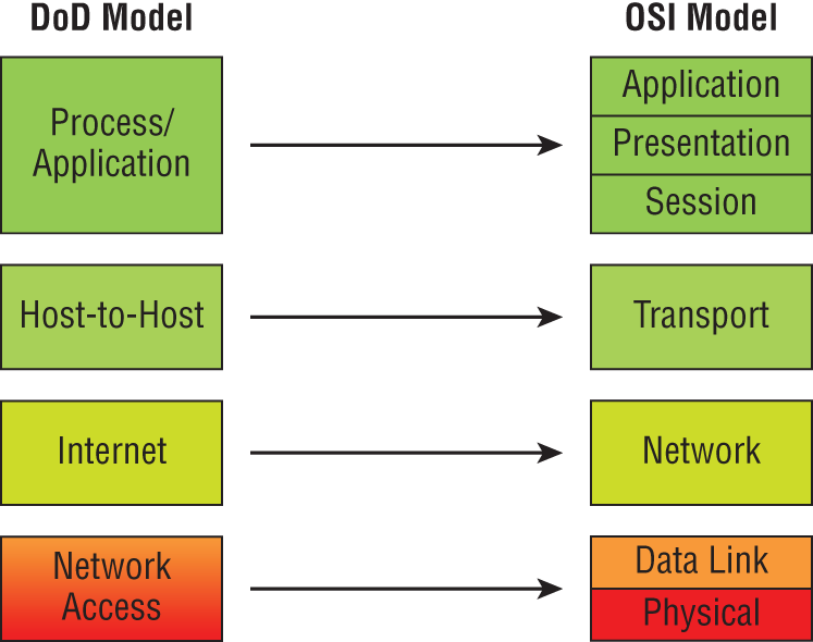
FIGURE 6.1 The DoD and OSI models
The Host-to-Host layer parallels the functions of the OSI's Transport layer, defining protocols for setting up the level of transmission service for applications. It tackles issues such as creating reliable end-to-end communication and ensuring the error-free delivery of data. It handles packet sequencing and maintains data integrity.
The Internet layer corresponds to the OSI's Network layer, designating the protocols relating to the logical transmission of packets over the entire network. It takes care of the logical addressing of hosts by giving them an IP address, and it handles the routing of packets among multiple networks.
At the bottom of the DoD model, the Network Access layer monitors the data exchange between the host and the network. The equivalent of the Data Link and Physical layers of the OSI model, the Network Access layer oversees hardware addressing and defines protocols for the physical transmission of data.
The DoD and OSI models are alike in design and concept and have similar functions in similar layers. Figure 6.2 shows the TCP/IP protocol suite and how its protocols relate to the DoD model layers.
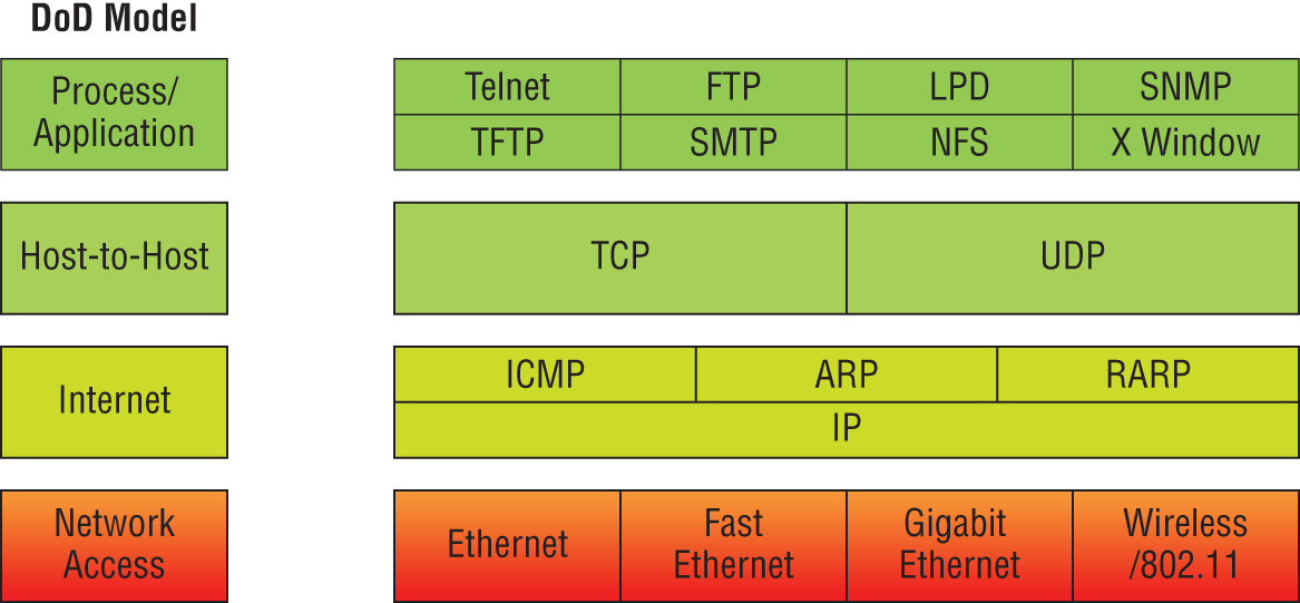
FIGURE 6.2 The TCP/IP protocol suite
We'll now look at the different protocols in more detail, starting with the Process/Application layer protocols.
The Process/Application Layer Protocols
In the following sections, I'll describe the different applications and services typically used in IP networks and list their associated port numbers as well, which are discussed in detail in this chapter.
File Transfer Protocol (TCP 20, 21)
File Transfer Protocol (FTP) is the protocol that actually lets you transfer files across an IP network, and it can accomplish this between any two machines that are using it. But FTP isn't just a protocol; it's also a program. Operating as a protocol, FTP is used by applications. As a program, it's employed by users to perform file tasks by hand. FTP also allows for access to both directories and files and can accomplish certain types of directory operations, such as relocating files into different directories. Figure 6.3 shows an FTP example.

FIGURE 6.3 File Transfer Protocol
Accessing a host through FTP is only the first step, though. Users must then be subjected to an authentication login that's probably secured with passwords and usernames implemented by system administrators to restrict access. You can get around this somewhat by adopting the username anonymous—although what you'll gain access to will be limited.
Even when employed by users manually as a program, FTP's functions are limited to listing and manipulating directories, typing file contents, and copying files between hosts. It can't execute remote files as programs. The problem with FTP is that all data is sent in clear text, just as with Telnet. If you need to make sure your FTP transfers are secure, then you'll use SFTP, which is covered after the next section.
Secure Shell (TCP 22)
The Secure Shell (SSH) protocol sets up a secure Telnet session over a standard TCP/IP connection and is employed for doing things like logging into other systems, running programs on remote systems, and moving files from one system to another. Figure 6.4 shows an SSH example.
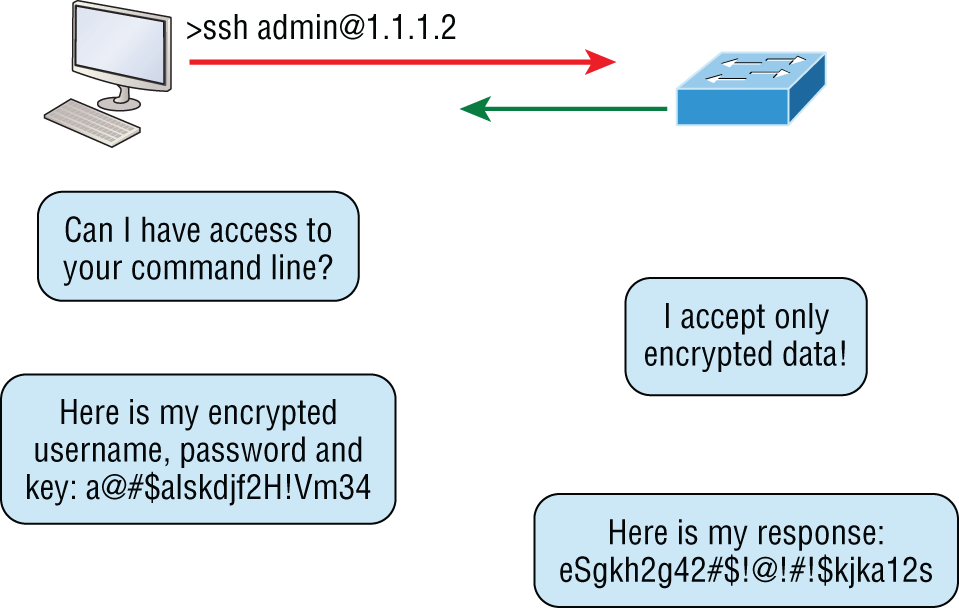
FIGURE 6.4 SSH
And it does all of this while maintaining a nice, strong, encrypted connection. You can think of it as the new-generation protocol that's now used in place of
rsh
and
rlogin
—even Telnet.
Secure File Transfer Protocol (TCP 22)
Secure File Transfer Protocol (SFTP) is used when you need to transfer files over an encrypted connection. It uses an SSH session (which was previously covered), which encrypts the connection, and SSH uses port 22, hence the port 22 for SFTP.
Apart from the secure part, it's used just as FTP is—for transferring files between computers on an IP network, such as the Internet.
Telnet (TCP 23)
Telnet is the chameleon of protocols—its specialty is terminal emulation. It allows a user on a remote client machine, called the Telnet client, to access the resources of another machine, the Telnet server. Telnet achieves this by pulling a fast one on the Telnet server and making the client machine appear as though it were a terminal directly attached to the local network. This projection is actually a software shell—a virtual terminal that can interact with the chosen remote host. Figure 6.5 shows a Telnet example.
These emulated terminals are of the text-mode type and can execute refined procedures such as displaying menus that give users the opportunity to choose options and access the applications on the duped server. Users begin a Telnet session by running the Telnet client software and then logging into the Telnet server.
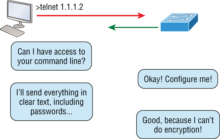
FIGURE 6.5 Telnet
Telnet offers no security or encryption and is replaced by Secure Shell (SSH) when security across the remote-configuration session is needed or desired.
Simple Mail Transfer Protocol (TCP 25)
Simple Mail Transfer Protocol (SMTP), answering our ubiquitous call to email, uses a spooled, or queued, method of mail delivery. Once a message has been sent to a destination, the message is spooled to a device—usually a disk. The server software at the destination posts a vigil, regularly checking the queue for messages. When it detects them, it proceeds to deliver them to their destination. SMTP is used to send mail; POP3 is used to receive mail.
Domain Name Service (TCP and UDP 53)
Domain Name Service (DNS) resolves hostnames—specifically, Internet names, such as www.lammle.com—to their corresponding IP addresses.
You don't have to use DNS; you can just type in the IP address of any device you want to communicate with. An IP address identifies hosts on a network and the Internet as well. However, DNS was designed to make our lives easier. Think about this: What would happen if you wanted to move your web page to a different service provider? The IP address would change, and no one would know what the new one was. DNS allows you to use a domain name to specify an IP address. You can change the IP address as often as you want and no one will know the difference. Figure 6.6 shows a DNS example.
DNS is used to resolve a fully qualified domain name (FQDN)—for example, www.lammle.com or todd.lammle.com—to an IP address. An FQDN, or DNS namespace, is a hierarchy that can logically locate a system based on its domain identifier.
If you want to resolve the name todd, you must either type in the FQDN of todd.lammle.com or have a device, such as a PC or router, add the suffix for you. For example, on a Cisco router, you can use the command ip domain-name lammle.com to append each request with the lammle.com domain. If you don't do that, you'll have to type in the FQDN to get DNS to resolve the name.

FIGURE 6.6 Domain Name Service
Dynamic Host Configuration Protocol/Bootstrap Protocol (UDP 67/68)
Dynamic Host Configuration Protocol (DHCP) assigns IP addresses to hosts with information provided by a server. It allows easier administration and works well in small to even very large network environments. Many types of hardware can be used as a DHCP server, including routers.
DHCP differs from Bootstrap Protocol (BootP) in that BootP assigns an IP address to a host but the host's hardware address must be entered manually in a BootP table. You can think of DHCP as a dynamic BootP. But remember that BootP is also used to send an operating system that a host can boot from. DHCP can't do that.
But there is a lot of information a DHCP server can provide to a host when the host is requesting an IP address from the DHCP server. Here's a partial list of the information a DHCP server can provide:
- IP address
- Subnet mask
- Domain name
- Default gateway (routers)
- DNS
- Windows Internet Naming Service (WINS) information
A DHCP server can give even more information than this, but the items in the list are the most common.
A client that sends out a DHCP Discover message in order to receive an IP address sends out a broadcast at both layer 2 and layer 3. The layer 2 broadcast is all Fs in hex, which looks like this: FF:FF:FF:FF:FF:FF. The Layer 3 broadcast is 255.255.255.255, which means all networks and all hosts. DHCP is connectionless, which means it uses User Datagram Protocol (UDP) at the Transport layer, also known as the Host-to-Host layer, which we'll talk about later.
In case you don't believe me, here's an example of output from my trusty analyzer:
Ethernet II,Src:192.168.0.3(00:0b:db:99:d3:5e),Dst:Broadcast(ff:ff:ff:ff:ff:ff)Internet Protocol,Src:0.0.0.0(0.0.0.0),Dst:255.255.255.255(255.255.255.255).
The Data Link and Network layers are both sending out “all hands” broadcasts saying, “Help! I don't know my IP address!”
Figure 6.7 shows the process of a client-server relationship using a DHCP connection.
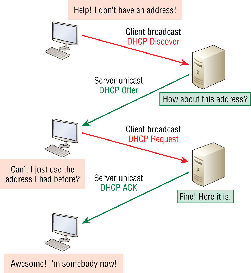
FIGURE 6.7 DHCP client four-step process
The following is the four-step process (sometimes known as the DORA process) a client takes to receive an IP address from a DHCP server:
- The DHCP client broadcasts a DHCP Discover message looking for a DHCP server (port 67).
- The DHCP server that received the DHCP Discover message sends a unicast DHCP Offer message back to the host.
- The client then broadcasts to the server a DHCP Request message asking for the offered IP address and possibly other information.
- The server finalizes the exchange with a unicast DHCP Acknowledgment message.
What happens if you have a few hosts connected together with a switch or hub and you don't have a DHCP server? You can add IP information by hand (this is called static IP addressing), or Windows provides what is called Automatic Private IP Addressing (APIPA), a feature of later Windows operating systems. With APIPA, clients can automatically self-configure an IP address and subnet mask (basic IP information that hosts use to communicate, which is covered in detail in Chapter 7, “IP Addressing,” and Chapter 8, “IP Subnetting, Troubleshooting IP, and Introduction to NAT”) when a DHCP server isn't available. The IP address range for APIPA is 169.254.0.1 through 169.254.255.254. The client also configures itself with a default Class B subnet mask of 255.255.0.0. If you have a DHCP server and your host is using this IP address, this means your DHCP client on your host is not working or the server is down or can't be reached because of a network issue.
Trivial File Transfer Protocol (UDP 69)
Trivial File Transfer Protocol (TFTP) is the stripped-down, stock version of FTP, but it's the protocol of choice if you know exactly what you want and where to find it—plus it's easy to use, and it's fast, too! It doesn't give you the abundance of functions that FTP does, though. TFTP has no directory-browsing abilities; it can do nothing but send and receive files. Figure 6.8 shows a TFTP example.
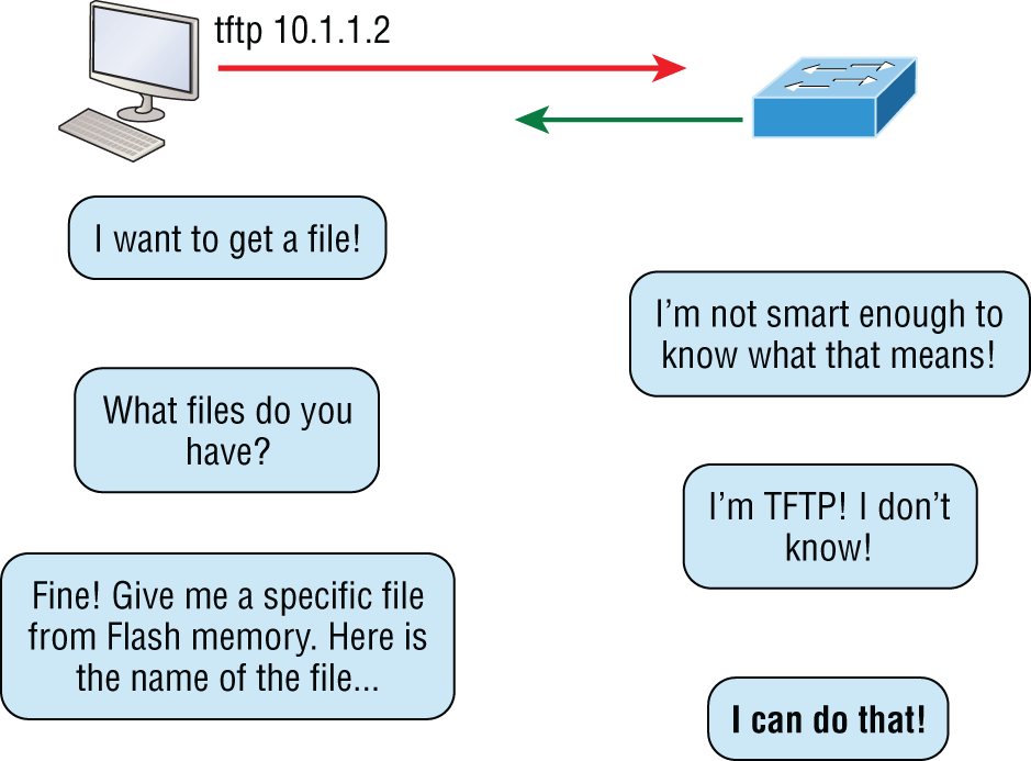
FIGURE 6.8 Trivial FTP
This compact little protocol also skimps in the data department, sending much smaller blocks of data than FTP, and there's no authentication as with FTP, so it's insecure. Few sites support it because of the inherent security risks.
Hypertext Transfer Protocol (TCP 80)
All those snappy websites comprising a mélange of graphics, text, links, and so on—the Hypertext Transfer Protocol (HTTP) is making it all possible. Figure 6.9 shows an HTTP example.
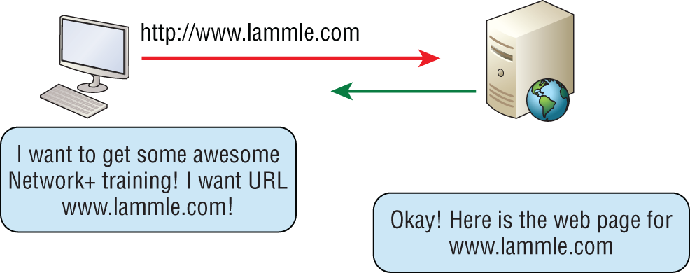
FIGURE 6.9 HTTP
HTTP is used to manage communications between web browsers and web servers, and it opens the right resource when you click a link, wherever that resource may actually reside. See the section on HTTPS for what we normally use today for this type of data transfer.
Post Office Protocol v3 (TCP 110)
Post Office Protocol (POP) gives us a storage facility for incoming mail, and the latest version is called POP3 (sound familiar?). Basically, how this protocol works is when a client device connects to a POP3 server, messages addressed to that client are released for downloading. It doesn't allow messages to be downloaded selectively, but once they are, the client-server interaction ends and you can delete and tweak your messages locally at will. A newer standard, IMAP, is being used more and more in place of POP3 because of security.
Network Time Protocol (UDP 123)
Kudos to Professor David Mills of the University of Delaware for coming up with this handy protocol that's used to synchronize the clocks on our computers to one standard time source (typically, an atomic clock). Network Time Protocol (NTP) works in conjunction with other synchronization utilities to ensure that all computers on a given network agree on the time. See Figure 6.10.
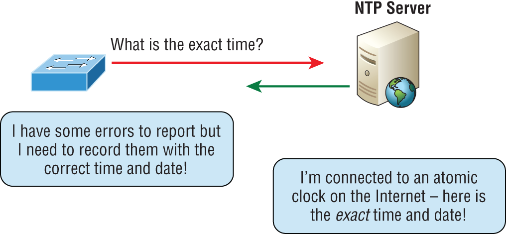
FIGURE 6.10 Network Time Protocol
This may sound pretty simple, but it's very important because so many of the transactions done today are time- and date-stamped. Think about your precious databases, for one. It can mess up a server pretty badly if it's out of sync with the machines connected to it, even by mere seconds (think crash!). You can't have a transaction entered by a machine at, say, 1:50 a.m. when the server records that transaction as having occurred at 1:45 a.m. So basically, NTP works to prevent “back to the future sans DeLorean” from bringing down the network—very important indeed!
Internet Message Access Protocol (TCP 143)
Because Internet Message Access Protocol (IMAP) makes it so you get control over how you download your mail, with it, you also gain some much-needed security. It lets you peek at the message header or download just a part of a message—you can now just nibble at the bait instead of swallowing it whole and then choking on the hook hidden inside!
With it, you can choose to store messages on the email server hierarchically and link to documents and user groups too. IMAP even gives you search commands to use to hunt for messages based on their subject, header, or content. As you can imagine, it has some serious authentication features—it actually supports the Kerberos authentication scheme that MIT developed. And yes, IMAP4 is the current version.
Simple Network Management Protocol (UDP 161/162)
Simple Network Management Protocol (SNMP) collects and manipulates valuable network information. It gathers data by polling the devices on the network from a management station at fixed or random intervals, requiring them to disclose certain information. When all is well, SNMP receives something called a baseline—a report delimiting the operational traits of a healthy network. This protocol can also stand as a watchdog over the network, quickly notifying managers of any sudden turn of events. The network watchdogs are called agents, and when aberrations occur, agents send an alert called a trap to the management station. The Network Management System (NMS) polls the agents through a Management Information Base (MIB). The MIB is basically a database with a set of predefined questions the NMS can ask the agents regarding the health of the device or network. Figure 6.11 shows an NMS station at work.

FIGURE 6.11 Network Management Station
In addition, SNMP can help simplify the process of setting up a network as well as the administration of your entire internetwork.
Lightweight Directory Access Protocol (TCP 389)
If you're the system administrator of any decent-sized network, odds are you have a type of directory in place that keeps track of all your network resources, such as devices and users. But how do you access those directories? Through the Lightweight Directory Access Protocol (LDAP), that's how. LDAP is a protocol used to access and query directory services systems such as Microsoft Active Directory. And there is a secure version of LDAP called LDAPS that uses port 636, which I'll cover a bit later.
This protocol standardizes how you access directories, and its first and second inceptions are described in RFCs 1487 and 1777, respectively. There were a few glitches in those two earlier versions, so a third version—the one most commonly used today—was created to address those issues and is described in RFC 3377.
Hypertext Transfer Protocol Secure (TCP 443)
Hypertext Transfer Protocol Secure (HTTPS) is a secure version of HTTP that arms you with a whole bunch of security tools for keeping transactions secure between a web browser and a server. It's what your browser needs to fill out forms, sign in, authenticate, and encrypt an HTTP message when you make a reservation or buy something online.
Transport Layer Security/Secure Sockets Layer (TCP 995/465)
Both Transport Layer Security (TLS) and its forerunner, Secure Sockets Layer (SSL), are cryptographic protocols that come in really handy for enabling secure online data-transfer activities like browsing the Web, instant messaging, Internet faxing, and so on. They're so similar that it's not within the scope of this book to detail the differences between them. They both use X.509 certificates and asymmetric cryptography to authenticate to the host they are communicating with and to exchange a key. This key is then used to encrypt data flowing between the hosts. This allows for data/message confidentiality, message integrity, and message authentication.
Even though I listed TLS/SSL as using ports 995 and 465, which is true if you're using Gmail, TLS/SSL isn't tied down to any certain ports and can use various different ones.
Server Message Block (TCP 445)
Server Message Block (SMB) is used for sharing access to files and printers and other communications between hosts on a Microsoft Windows network. SMB runs mostly on TCP port 445 now, but SMB can also run on UDP port 137 and 138 and on TCP port 137 and 139 using NetBIOS.
Syslog (UDP 514)
Reading system messages from a switch's or router's internal buffer is the most popular and efficient method of seeing what's going on with your network at a particular time. But the best way is to log messages to a syslog server, which stores messages from you and can even time-stamp and sequence them for you, and it's easy to set up and configure!
Syslog allows you to display, sort, and even search messages, all of which makes it a really great troubleshooting tool. The search feature is especially powerful because you can use keywords and even severity levels. Plus, the server can email admins based on the severity level of the message.
Network devices can be configured to generate a syslog message and forward it to various destinations. These four examples are popular ways to gather messages from Cisco devices:
- Logging buffer (on by default)
- Console line (on by default)
- Terminal lines (using the
terminal monitorcommand) - Syslog server
The severity levels, from the most severe level to the least severe, are explained in Table 6.1. Information is the default and will result in all messages being sent to the buffers and console.
TABLE 6.1 Severity levels
| Severity Level | Explanation |
|---|---|
| Emergency (severity 0) | System is unusable. |
| Alert (severity 1) | Immediate action is needed. |
| Critical (severity 2) | Critical condition. |
| Error (severity 3) | Error condition. |
| Warning (severity 4) | Warning condition. |
| Notification (severity 5) | Normal but significant condition. |
| Information (severity 6) | Normal information message. |
| Debugging (severity 7) | Debugging message. |
SMTP TLS (TCP 587)
As discussed previously, Simple Mail Transfer Protocol (SMTP), answers our ubiquitous call to email, uses a spooled, or queued, method of mail delivery using TCP port 25. However, this email is sent in clear text and some email servers can still use this.
SMTP TLS encrypts email when it is sent, and most email servers use or can use port 587 to send email now, some even demand it. This port, coupled with TLS encryption, will ensure that email is securely sent, following the guidelines set out by the IETF of course.
Lightweight Directory Access Protocol over SSL (TCP 636)
Building on our discussion earlier on TCP 389 LDAP, understand that this traffic is transmitted unsecured. Bring in LDAP over SSL TCP 636, which is the suggested use of LDAP in today's networks. To make this function correctly, you just need to install a proper certificate from a Microsoft certification authority (CA) or other type of CA.
IMAP over SSL (TCP 993)
Because Internet Message Access Protocol (IMAP) ensures that you get control over how you download your mail, with it, you also gain some much-needed security. However, IMAP over SSL means that IMAP traffic travels over a security socket to a security port, using TCP port 993 usually.
POP3 over SSL (TCP 995)
As discussed previously, Post Office Protocol (POP) gives us a storage facility for incoming mail, and the latest version of POP is called POP3. You can probably guess that this email is downloaded in clear text. Either POP3 over SSL or IMAP over SSL is more commonly used to encrypt emails being download from servers today.
Structured Query Language (SQL) Server (TCP 1433)
Microsoft SQL Server has grown from a simple relational database engine to a multipurpose enterprise-level data platform. TCP port 1433 is the default port for SQL Server, and it's also the official Internet Assigned Number Authority (IANA) socket number for SQL Server. Client systems use TCP 1433 to connect to the database engine.
SQLnet (TCP 1521)
SQLnet (also referred to as SQL*Net and Net8) is Oracle's networking software that allows remote data access between programs using Oracles Database. Applications and databases are shared with different machines and continue to communicate as if they were local.
SQLnet is based on Oracle's Transparent Network Substrate (TNS), a network technology that provides a generic interface to all network protocols; however, you can guess this is no longer needed today since we have TCP/IP.
SQL*Net is used by both client and server to communicate with one another. Without the Net8 layer acting as the interpreter, the client process and the server process are unable to interconnect (noticed how I used all three names in this section—all define the same thing).
MySQL (TCP 3306)
MySQL is a relational database management system based on Structured Query Language (SQL). This is used within companies for data warehousing, e-commerce, logging applications, and more. The most common use for MySQL is for the purpose of a cloud-based database.
Remote Desktop Protocol (TCP 3389)
Remote Desktop Protocol (RDP) is a proprietary protocol developed by Microsoft. It allows you to connect to another computer and run programs. RDP operates somewhat like Telnet, except instead of getting a command-line prompt as you do with Telnet, you get the actual graphical user interface (GUI) of the remote computer. Clients exist for most versions of Windows, and Macs now come with a preinstalled RDP client.
Microsoft currently calls its official RDP server software Remote Desktop Services; it was called Terminal Services for a while. Microsoft's official client software is currently referred to as Remote Desktop Connection (RDC), which was called Terminal Services Client in the past.
RDP is an excellent tool for remote clients, allowing users to connect to their work computer from home, for example, and get their email or perform work on other applications without running or installing any of the software on their home computer.
SIP (VoIP) (TCP or UDP 5060/TCP 5061)
Session Initiation Protocol (SIP) is a hugely popular signaling protocol used to construct and deconstruct multimedia communication sessions for many things like voice and video calls, videoconferencing, streaming multimedia distributions, instant messaging, presence information, and online games over the Internet.
RTP (VoIP) (UDP 5004/TCP 5005)
Real-time Transport Protocol (RTP) describes a packet-formatting standard for delivering audio and video over the Internet. Although initially designed as a multicast protocol, it's now used for unicast applications too. It's commonly employed for streaming media, videoconferencing, and push-to-talk systems—all things that make it a de facto standard in Voice over IP (VoIP) industries.
MGCP (Multimedia) (TCP 2427/2727)
Media Gateway Control Protocol (MGCP) is a standard protocol for handling the signaling and session management needed during a multimedia conference.
The protocol defines a means of communication between a media gateway, which converts data from the format required for a circuit-switched network to that required for a packet-switched network, and the media gateway controller.
MGCP can be used to set up, maintain, and terminate calls between multiple endpoints.
H.323 (Video) (TCP 1720)
H.323 is a protocol that provides a standard for video on an IP network that defines how real-time audio, video, and data information is transmitted. This standard provides signaling, multimedia, and bandwidth control mechanisms. H.323 uses the RTP standard for communication.
Internet Group Management Protocol
Internet Group Management Protocol (IGMP) is the TCP/IP protocol used for managing IP multicast sessions. It accomplishes this by sending out unique IGMP messages over the network to reveal the multicast-group landscape and to find out which hosts belong to which multicast group. The host machines in an IP network also use IGMP messages to become members of a group and to quit the group too. IGMP messages come in seriously handy for tracking group memberships as well as active multicast streams. IGMP works at the Network layer and doesn't use port numbers.
NetBIOS (TCP and UDP 137–139)
Network Basic Input/Output System works only in the upper layers of the OSI model and allows for an interface on separate computers to communicate over a network.
It was first created in the early 1980s to work on an IBM LAN and was proprietary. Microsoft and Novell both created a NetBIOS implementation to allow their hosts to communicate to their servers, but Microsoft's version became the de facto version.
The Host-to-Host Layer Protocols
The main purpose of the Host-to-Host layer is to shield the upper-layer applications from the complexities of the network. This layer says to the upper layer, “Just give me your data stream, with any instructions, and I'll begin the process of getting your information ready to send.”
The following sections describe the two protocols at this layer:
- Transmission Control Protocol (TCP)
- User Datagram Protocol (UDP)
In addition, we'll look at some of the key host-to-host protocol concepts as well as the port numbers.
Transmission Control Protocol
Transmission Control Protocol (TCP) takes large blocks of information from an application and breaks them into segments. It numbers and sequences each segment so that the destination's TCP process can put the segments back into the order the application intended. After these segments are sent, TCP (on the transmitting host) waits for an acknowledgment from the receiving end's TCP process, retransmitting those segments that aren't acknowledged.
Remember that in a reliable transport operation, a device that wants to transmit sets up a connection-oriented communication with a remote device by creating a session. The transmitting device first establishes a connection-oriented session with its peer system; that session is called a call setup or a three-way handshake. Data is then transferred, and when the transfer is complete, a call termination takes place to tear down the virtual circuit.
TCP is a full-duplex, connection-oriented, reliable, and accurate protocol, but establishing all these terms and conditions, in addition to error checking, is no small task. TCP is very complicated, and so not surprisingly, it's costly in terms of network overhead. And since today's networks are much more reliable than those of yore, this added reliability is often unnecessary. Most programmers use TCP because it removes a lot of programming work, but for real-time video and VoIP, User Datagram Protocol (UDP) is often better because using it results in less overhead.
TCP Segment Format
Because the upper layers just send a data stream to the protocols in the Transport layers, I'll use Figure 6.12 to demonstrate how TCP segments a data stream and prepares it for the Internet layer. When the Internet layer receives the data stream, it routes the segments as packets through an internetwork. The segments are handed to the receiving host's Host-to-Host layer protocol, which rebuilds the data stream for the upper-layer applications or protocols.
The TCP header is 24 bytes long, or up to 60 bytes with options. Figure 6.12 shows the TCP segment format and the different fields within the TCP header.

FIGURE 6.12 TCP segment format
Again, it's good to understand what each field in the TCP segment is in order to build a strong educational foundation:
- Source Port This is the port number of the application on the host sending the data, which I'll talk about more thoroughly a little later in the Port Numbers section.
- Destination Port This is the port number of the application requested on the destination host.
- Sequence Number A number used by TCP that puts the data back in the correct order or retransmits missing or damaged data during a process called sequencing.
- Acknowledgment Number The value is the TCP octet that is expected next.
- Header Length The number of 32-bit words in the TCP header, which indicates where the data begins. The TCP header (even one including options) is an integral number of 32 bits in length.
- Reserved Always set to zero.
- Code Bits/TCP Flags Controls functions used to set up and terminate a session.
- Window The window size the sender is willing to accept, in octets.
- Checksum The cyclic redundancy check (CRC), used because TCP doesn't trust the lower layers and checks everything. The CRC checks the header and data fields.
- Urgent A valid field only if the Urgent pointer in the code bits is set. If so, this value indicates the offset from the current sequence number, in octets, where the segment of non-urgent data begins.
- Options May be 0, meaning that no options have to be present, or a multiple of 32 bits. However, if any options are used that do not cause the option field to total a multiple of 32 bits, padding of 0s must be used to make sure the data begins on a 32-bit boundary. These boundaries are known as words.
- Payload (Data) Handed down to the TCP protocol at the Transport layer, which includes the upper-layer headers.
Let's take a look at a TCP segment copied from a network analyzer. In the following output, I have bolded the Payload (data) area that the packet is carrying to the destination host:
TCP - Transport Control ProtocolSource Port: 5973Destination Port: 23Sequence Number: 1456389907Ack Number: 1242056456Offset: 5Reserved: %000000Code: %011000Ack is validPush RequestWindow: 61320Checksum: 0x61a6Urgent Pointer: 0No TCP OptionsTCP Data Area:vL.5.+.5.+.5.+.5 76 4c 19 35 11 2b 19 35 11 2b 19 35 112b 19 35 +. 11 2b 19Frame Check Sequence: 0x0d00000f
Did you notice that everything I talked about earlier is in the segment? As you can see from the number of fields in the header, TCP creates a lot of overhead. Again, this is why application developers may opt for efficiency over reliability to save overhead and go with UDP instead. It's also defined at the Transport layer as an alternative to TCP.
User Datagram Protocol
If you were to compare User Datagram Protocol (UDP) with TCP, the former is basically the scaled-down economy model that's sometimes referred to as a thin protocol. Like a thin person on a park bench, a thin protocol doesn't take up a lot of room—or in this case, much bandwidth on a network.
UDP doesn't offer all the bells and whistles of TCP either, but it does do a fabulous job of transporting information that doesn't require reliable delivery—and it does so using far fewer network resources.
There are some situations in which it would definitely be wise for developers to opt for UDP rather than TCP. Remember the watchdog SNMP up there at the Process/Application layer? SNMP monitors the network, sending intermittent messages and a fairly steady flow of status updates and alerts, especially when running on a large network. The cost in overhead to establish, maintain, and close a TCP connection for each one of those little messages would reduce what would be an otherwise healthy, efficient network to a dammed-up bog in no time!
Another circumstance calling for UDP over TCP is when reliability is already handled at the Process/Application layer. DNS handles its own reliability issues, making the use of TCP both impractical and redundant. But ultimately, it's up to the application developer to decide whether to use UDP or TCP, not the user who wants to transfer data faster.
UDP does not sequence the segments and doesn't care in which order the segments arrive at the destination. But after that, UDP sends the segments off and forgets about them. It doesn't follow through, check up on them, or even allow for an acknowledgment of safe arrival—complete abandonment. Because of this, it's referred to as an unreliable protocol. This doesn't mean that UDP is ineffective, only that it doesn't handle issues of reliability. Because UDP assumes that the application will use its own reliability method, it doesn't use any. This gives an application developer a choice when running the IP stack: TCP for reliability or UDP for faster transfers.
Further, UDP doesn't create a virtual circuit, nor does it contact the destination before delivering information to it. Because of this, it's also considered a connectionless protocol.
Figure 6.13 clearly illustrates UDP's markedly low overhead as compared to TCP's hungry usage. Look at the figure carefully—can you see that UDP doesn't use windowing or provide for acknowledgments in the UDP header?
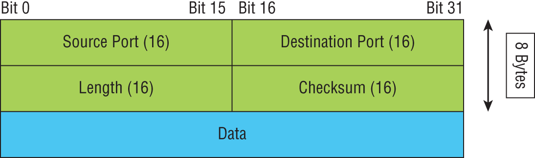
FIGURE 6.13 UDP segment
Key Concepts of Host-to-Host Protocols
Now that you've seen both a connection-oriented (TCP) and connectionless (UDP) protocol in action, it would be good to summarize the two here. Table 6.2 highlights some of the key concepts that you should keep in mind regarding these two protocols. You should memorize this table.
TABLE 6.2 Key features of TCP and UDP
| TCP | UDP |
|---|---|
| Sequenced | Unsequenced |
| Reliable | Unreliable |
| Connection-oriented | Connectionless |
| Virtual circuit | Low overhead |
| Acknowledgments | No acknowledgment |
| Windowing flow control | No windowing or flow control of any type |
A telephone analogy could really help you understand how TCP works. Most of us know that before you speak to someone on a phone, you must first establish a connection with that person—wherever they are. This is like a virtual circuit with TCP. If you were giving someone important information during your conversation, you might say, “You know?” or ask, “Did you get that?” Saying something like this is a lot like a TCP acknowledgment—it's designed to get your verification. From time to time (especially on cell phones), people also ask, “Are you still there?” They end their conversations with a “Good-bye” of some kind, putting closure on the phone call. TCP also performs these types of functions.
Alternatively, using UDP is like sending a postcard. To do that, you don't need to contact the other party first. You simply write your message, address the postcard, and mail it. This is analogous to UDP's connectionless orientation. Because the message on the postcard is probably not a matter of life or death, you don't need an acknowledgment of its receipt. Similarly, UDP doesn't involve acknowledgments.
Port Numbers
TCP and UDP must use port numbers to communicate with the upper layers because they're what keeps track of different simultaneous conversations originated or accepted by the local host. Originating source port numbers are dynamically assigned by the source host and will usually have a value of 1024 or higher. Ports 1023 and below are defined in RFC 3232, which discusses what are called well-known port numbers.
Virtual circuits that don't use an application with a well-known port number are assigned port numbers randomly from a specific range instead. These port numbers identify the source and destination application or process in the TCP segment.
Figure 6.14 illustrates how both TCP and UDP use port numbers.
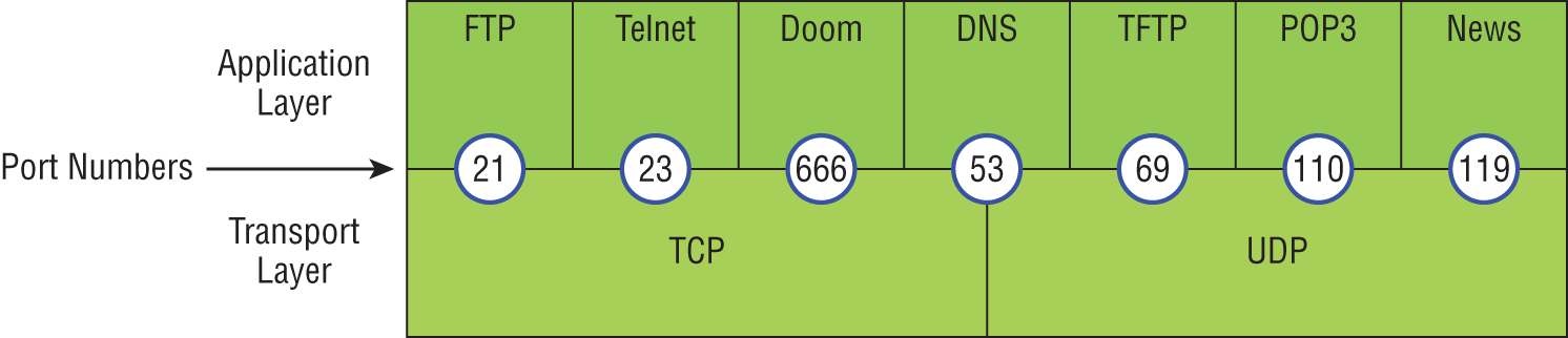
FIGURE 6.14 Port numbers for TCP and UDP
You just need to remember that numbers below 1024 are considered well-known port numbers and are defined in RFC 3232. Numbers 1024 and above are used by the upper layers to set up sessions with other hosts and by TCP as source and destination identifiers in the TCP segment.
Table 6.3 gives you a list of the typical applications used in the TCP/IP suite, their well-known port numbers, and the Transport layer protocols used by each application or process. It's important that you study and memorize this table for the CompTIA Network+ exam.
TABLE 6.3 Key protocols that use TCP and UDP
| TCP | UDP |
|---|---|
| Telnet 23 | SNMPv1/2 161 |
| SMTP 25 | TFTP 69 |
| HTTP 80 | DNS 53 |
| FTP 20, 21 | BOOTPS/DHCP 67,68 |
| SFTP 22 | NTP 123 |
| DNS 53 | |
| HTTPS 443 | |
| SSH 22 | |
| SMB 445 | |
| POP3 110 | |
| IMAP4 143 | |
| RDP 3389 | |
| SNMPv3 161 |
Notice that DNS uses both TCP and UDP. Whether it opts for one or the other depends on what it's trying to do. Even though it's not the only application that can use both protocols, it's certainly one that you should remember in your studies.
The Internet Layer Protocols
In the DoD model, there are two main reasons for the Internet layer's existence: routing and providing a single network interface to the upper layers.
None of the other upper- or lower-layer protocols have any functions relating to routing—that complex and important task belongs entirely to the Internet layer. The Internet layer's second duty is to provide a single network interface to the upper-layer protocols. Without this layer, application programmers would need to write what are called hooks into every one of their applications for each different Network Access protocol. This would not only be a pain in the neck, it would also lead to different versions of each application—one for Ethernet, another one for Token Ring, and so on. To prevent this, IP provides one single network interface for the upper-layer protocols. That accomplished, it's then the job of IP and the various Network Access protocols to get along and work together.
All network roads don't lead to Rome—they lead to IP. And all the other protocols at this layer, as well as all those at the upper layers, use it. Never forget that. All paths through the DoD model go through IP. The following sections describe the protocols at the Internet layer:
- Internet Protocol (IP)
- Internet Control Message Protocol (ICMP)
- Address Resolution Protocol (ARP)
- Reverse Address Resolution Protocol (RARP)
- GRE/IPSec
Internet Protocol
Internet Protocol (IP) is essentially the Internet layer. The other protocols found here merely exist to support it. IP holds the big picture and could be said to “see all” in that it's aware of all the interconnected networks. It can do this because all the machines on the network have a software, or logical, address called an IP address, which I'll cover more thoroughly in the next chapter.
IP looks at each packet's destination address. Then, using a routing table, it decides where a packet is to be sent next, choosing the best path. The protocols of the Network Access layer at the bottom of the DoD model don't possess IP's enlightened scope of the entire network; they deal only with physical links (local networks).
Identifying devices on networks requires answering these two questions: Which network is it on? And what is its ID on that network? The answer to the first question is the software address, or logical address (the correct street). The answer to the second question is the hardware address (the correct mailbox). All hosts on a network have a logical ID called an IP address. This is the software, or logical, address and contains valuable encoded information, greatly simplifying the complex task of routing. (IP is discussed in RFC 791.)
IP receives segments from the Host-to-Host layer and fragments them into packets if necessary. IP then reassembles packets back into segments on the receiving side. Each packet is assigned the IP address of the sender and of the recipient. Each router (Layer 3 device) that receives a packet makes routing decisions based on the packet's destination IP address.
Figure 6.15 shows an IPv4 header. This will give you an idea of what IP has to go through every time user data is sent from the upper layers to a remote network.
The following fields make up the IP header:
- Version IP version number.
- Header Length Header length (HLEN) in 32-bit words.
- Priority and Type of Service Type of Service tells how the datagram should be handled. The first 3 bits are the priority bits, now called the differentiated services bits.
- Total Length Length of the packet, including header and data.
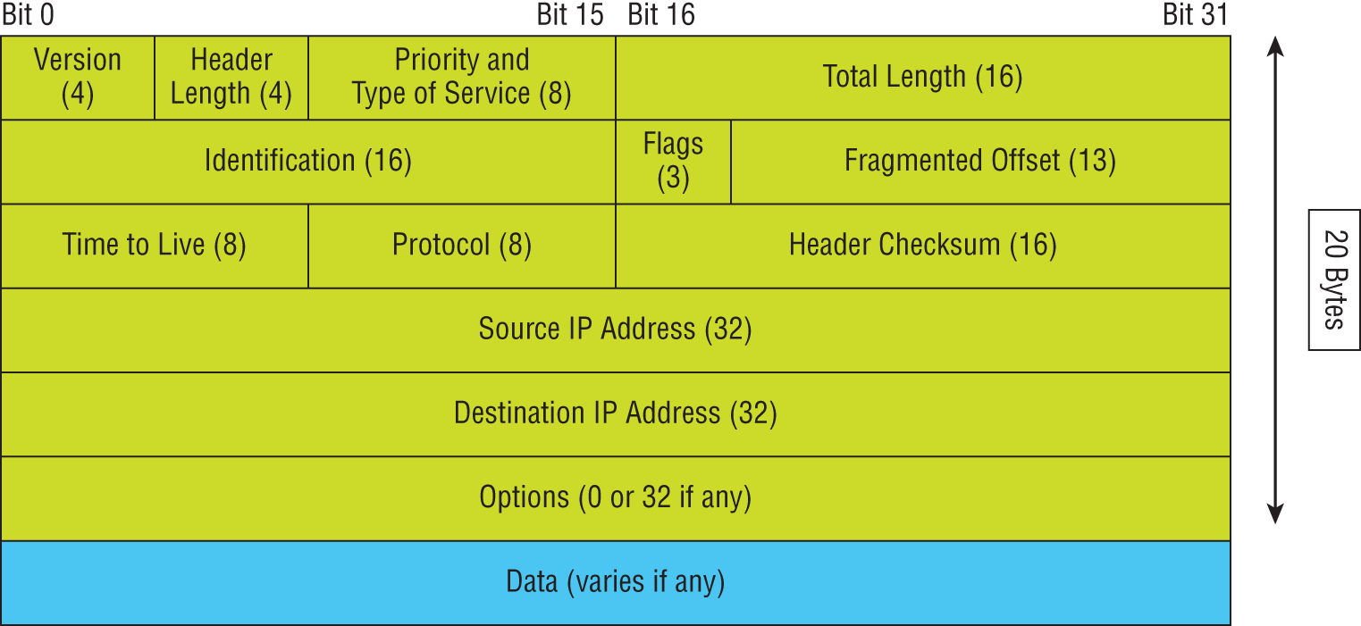
FIGURE 6.15 IPv4 header
- Identification Unique IP-packet value used to differentiate fragmented packets from different datagrams.
- Flags This one field specifies whether fragmentation of the packet should occur.
- Fragment Offset Provides fragmentation and reassembly if the packet is too large to put in a frame. It also allows different maximum transmission units (MTUs define the size of packets) on the Internet.
- Time To Live The time to live (TTL) is set into a packet when it is originally generated. If it doesn't get to where it's supposed to go before the TTL expires, boom—it's gone. This stops IP packets from continuously circling the network looking for a home.
- Protocol Port of upper-layer protocol; for example, TCP is port 6 or UDP is port 17. Also supports Network layer protocols, like ARP and ICMP, and can be referred to as the Type field in some analyzers. We'll talk about this field more in a minute.
- Header Checksum Cyclic redundancy check (CRC) on header only.
- Source IP Address 32-bit IP address of sending station.
- Destination IP Address 32-bit IP address of the station this packet is destined for.
- Options Used for network testing, debugging, security, and more.
- Data After the IP option field, will be the upper-layer data.
Here's a snapshot of an IP packet caught on a network analyzer. Notice that all the header information discussed previously appears here:
IP Header - Internet Protocol DatagramVersion: 4Header Length: 5Precedence: 0Type of Service: %000Unused: %00Total Length: 187Identifier: 22486Fragmentation Flags: %010 Do Not FragmentFragment Offset: 0Time To Live: 60IP Type: 0x06 TCPHeader Checksum: 0xd031Source IP Address: 10.7.1.30Dest. IP Address: 10.7.1.10No Internet Datagram Options
The Type field is typically a Protocol field, but this analyzer sees it as an IP Type field. This is important. If the header didn't carry the protocol information for the next layer, IP wouldn't know what to do with the data carried in the packet. The preceding example clearly tells IP to hand the segment to TCP.
Figure 6.16 demonstrates how the Network layer sees the protocols at the Transport layer when it needs to hand a packet up to the upper-layer protocols.

FIGURE 6.16 The Protocol field in an IP header
In this example, the Protocol field tells IP to send the data to either TCP port 6 or UDP port 17. But it will be UDP or TCP only if the data is part of a data stream headed for an upper-layer service or application. It could just as easily be destined for Internet Control Message Protocol (ICMP), Address Resolution Protocol (ARP), or some other type of Network layer protocol.
Table 6.4 is a list of some other popular protocols that can be specified in the Protocol field.
TABLE 6.4 Possible protocols found in the Protocol field of an IP header
| Protocol | Protocol Number |
|---|---|
| ICMP | 1 |
| IP in IP (tunneling) | 4 |
| TCP | 6 |
| UDP | 17 |
| EIGRP | 88 |
| OSPF | 89 |
| IPv6 | 41 |
| GRE | 47 |
| Layer 2 tunnel (L2TP) | 115 |
Internet Control Message Protocol
Internet Control Message Protocol (ICMP) works at the Network layer and is used by IP for many different services. ICMP is a management protocol and messaging service provider for IP. Its messages are carried as IP packets.
ICMP packets have the following characteristics:
- They can provide hosts with information about network problems.
- They are encapsulated within IP datagrams.
The following are some common events and messages that ICMP relates to, and the two most popular programs that use ICMP:
- Destination Unreachable If a router can't send an IP datagram any further, it uses ICMP to send a message back to the sender, advising it of the situation. For example, take a look at Figure 6.17, which shows that the Ethernet interface of the Lab B router is down.
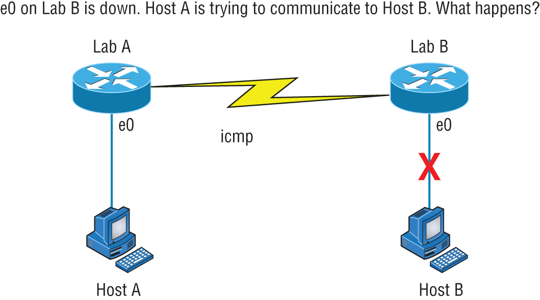
FIGURE 6.17 ICMP error message is sent to the sending host from the remote router
When Host A sends a packet destined for Host B, the Lab B router will send an ICMP Destination Unreachable message back to the sending device (directly to Host A, in this example).
- Buffer Full If a router's memory buffer for receiving incoming datagrams is full, it will use ICMP to send out this message until the congestion abates.
- Hops Each IP datagram is allotted a certain number of routers, called hops, to pass through. If a datagram reaches its limit of hops before arriving at its destination, the last router to receive it deletes it. The executioner router then uses ICMP to send an obituary message, informing the sending machine of the demise of its datagram.
- Ping Ping uses ICMP echo request and reply messages to check the physical and logical connectivity of machines on an internetwork.
- Traceroute Traceroute uses IP packet time to live time-outs to discover the path a packet takes as it traverses an internetwork.
Address Resolution Protocol
Address Resolution Protocol (ARP) finds the hardware address of a host from a known IP address. Here's how it works: When IP has a datagram to send, it must inform a Network Access protocol, such as Ethernet or Token Ring, of the destination's hardware address on the local network. (It has already been informed by upper-layer protocols of the destination's IP address.) If IP doesn't find the destination host's hardware address in the ARP cache, it uses ARP to find this information.
As IP's detective, ARP interrogates the local network by sending out a broadcast asking the machine with the specified IP address to reply with its hardware address. So basically, ARP translates the software (IP) address into a hardware address—for example, the destination machine's Ethernet address. Figure 6.18 shows how an ARP broadcast looks to a local network.

FIGURE 6.18 Local ARP broadcast
The following trace shows an ARP broadcast—notice that the destination hardware address is unknown and is all 0s in the ARP header. In the Ethernet header, a destination of all Fs in hex (all 1s in binary), a hardware-address broadcast, is used to make sure all devices on the local link receive the ARP request:
Flags: 0x00Status: 0x00Packet Length: 64Timestamp: 09:17:29.574000 12/06/21Ethernet HeaderDestination: FF:FF:FF:FF:FF:FF Ethernet BroadcastSource: 00:A0:24:48:60:A5Protocol Type: 0x0806 IP ARPARP - Address Resolution ProtocolHardware: 1 Ethernet (10Mb)Protocol: 0x0800 IPHardware Address Length: 6Protocol Address Length: 4Operation: 1 ARP RequestSender Hardware Address: 00:A0:24:48:60:A5Sender Internet Address: 172.16.10.3Target Hardware Address: 00:00:00:00:00:00 (ignored)Target Internet Address: 172.16.10.10Extra bytes (Padding):……………. 0A 0A 0A 0A 0A 0A 0A 0A 0A 0A 0A 0A 0A0A 0A 0A 0A 0AFrame Check Sequence: 0x00000000
Reverse Address Resolution Protocol (RARP)
When an IP machine happens to be a diskless machine, it has no way of initially knowing its IP address. But it does know its MAC address. Reverse Address Resolution Protocol (RARP) discovers the identity of the IP address for diskless machines by sending out a packet that includes its MAC address and a request for the IP address assigned to that MAC address. A designated machine, called a RARP server, responds with the answer, and the identity crisis is over. RARP uses the information it does know about the machine's MAC address to learn its IP address and complete the machine's ID portrait.
Figure 6.19 shows a diskless workstation asking for its IP address with a RARP broadcast.

FIGURE 6.19 RARP broadcast example
Generic Routing Encapsulation (GRE)
Generic Routing Encapsulation (GRE) is a tunneling protocol that can encapsulate many protocols inside IP tunnels. Some examples would be routing protocols such as EIGRP and OSPF and the routed protocol IPv6. Figure 6.20 shows the different pieces of a GRE header.
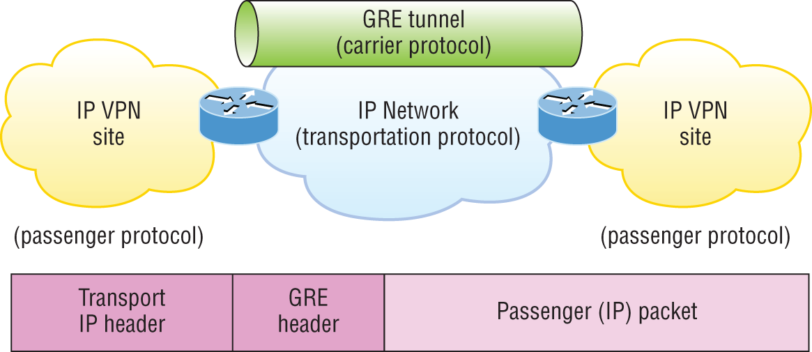
FIGURE 6.20 Generic Routing Encapsulation (GRE) tunnel structure
A GRE tunnel interface supports a header for each of the following:
- A passenger protocol or encapsulated protocols like IP or IPv6, which is the protocol being encapsulated by GRE
- GRE encapsulation protocol
- A transport delivery protocol, typically IP
GRE tunnels have the following characteristics:
- GRE uses a protocol-type field in the GRE header so any layer 3 protocol can be used through the tunnel.
- GRE is stateless and has no flow control.
- GRE offers no security.
- GRE creates additional overhead for tunneled packets—at least 24 bytes.
Internet Protocol Security (IPSec)
As I just mentioned, GRE by itself provides no security—no form of payload confidentiality or encryption. If the packets are sniffed over the public networks, their contents are in plaintext, and although IPsec provides a secure method for tunneling data across an IP network, it has limitations.
IPSec does not support IP broadcast or IP multicast, preventing the use of protocols that need them, like routing protocols. IPSec also does not support the use of the multiprotocol traffic. GRE is a protocol that can be used to “carry” other passenger protocols like IP broadcast or IP multicast, as well as non-IP protocols. So using GRE tunnels with IPSec allows you to run a routing protocol, IP multicast, as well as multiprotocol traffic across your network.
With a generic hub-and-spoke topology (Corp to Branch for example), you can implement static tunnels, typically GRE over IPSec, between the corporate office and branch offices. When you want to add a new spoke to the network, all you need to do is configure it on the hub router. The traffic between spokes has to traverse the hub, where it must exit one tunnel and enter another. Static tunnels can be an appropriate solution for small networks, but this solution actually becomes an unacceptable problem as the number of spokes grows larger and larger!
Authentication Header (AH)/Encapsulating Security Payload (ESP)
The two primary security protocols used by IPSec are Authentication Header (AH) and Encapsulating Security Payload (ESP).
Authentication Header (AH)
The AH protocol provides authentication for the data and the IP header of a packet using a one-way hash for packet authentication. It works like this: The sender generates a one-way hash; then the receiver generates the same one-way hash. If the packet has changed in any way, it won't be authenticated and will be dropped. So basically, IPsec relies upon AH to guarantee authenticity. AH checks the entire packet, but it doesn't offer any encryption services.
This is unlike ESP, which only provides an integrity check on the data of a packet.
Encapsulating Security Payload (ESP)
It won't tell you when or how the NASDAQ's gonna bounce up and down like a superball, but ESP will provide confidentiality, data origin authentication, connectionless integrity, anti-replay service, and limited traffic-flow confidentiality by defeating traffic flow analysis—which is almost as good! Anyway, there are five components of ESP:
- Confidentiality (Encryption) This allows the sending device to encrypt the packets before transmitting in order to prevent eavesdropping. Confidentiality is provided through the use of symmetric encryption algorithms. Confidentiality can be selected separately from all other services, but the confidentiality selected must be the same on both endpoints of your VPN. The following cryptographic algorithms are defined for use with IPSec:
- HMAC-SHA1/SHA2 for integrity protection and authenticity
- TripleDES-CBC for confidentiality
- AES-CBC and AES-CBC for confidentiality
- AES-GCM AND ChaCha20-Poly1305 providing confidentiality and authentication together efficiently
- Data Integrity Data integrity allows the receiver to verify that the data received was not altered in any way along the way. IPSec uses checksums as a simple check of the data.
- Authentication Authentication ensures that the connection is made with the correct partner. The receiver can authenticate the source of the packet by guaranteeing and certifying the source of the information.
- Anti-Replay Service Anti-replay election is based upon the receiver, meaning the service is effective only if the receiver checks the sequence number. In case you were wondering, a replay attack is when a hacker nicks a copy of an authenticated packet and later transmits it to the intended destination. When the duplicate, authenticated IP packet gets to the destination, it can disrupt services and generally wreak havoc. The Sequence Number field is designed to foil this type of attack.
- Traffic Flow For traffic flow confidentiality to work, you have to have at least tunnel mode selected. It's most effective if it's implemented at a security gateway where tons of traffic amasses because it's precisely the kind of environment that can mask the true source-destination patterns to bad guys who are trying to breach your network's security.
Data Encapsulation
I started to discuss data encapsulation in Chapter 2, but I could only provide an overview at that point in the book because you needed to have a firm understanding of how ports work in a virtual circuit. With the last five chapters of foundational material under your belt, you're ready to get more into the details of encapsulation.
When a host transmits data across a network to another device, the data goes through encapsulation: It's wrapped with protocol information at each layer of the OSI model. Each layer communicates only with its peer layer on the receiving device.
To communicate and exchange information, each layer uses protocol data units (PDUs). These hold the control information attached to the data at each layer of the model. They're usually attached to the header in front of the data field but can also be in the trailer, or end, of it.
Each PDU attaches to the data by encapsulating it at each layer of the OSI model, and each has a specific name depending on the information provided in each header. This PDU information is read only by the peer layer on the receiving device. After it's read, it's stripped off, and the data is then handed to the next layer up.
Figure 6.21 shows the PDUs and how they attach control information to each layer. This figure demonstrates how the upper-layer user data is converted for transmission on the network.
The data stream is then handed down to the Transport layer, which sets up a virtual circuit to the receiving device by sending over a synch packet. Next, the data stream is broken up into smaller pieces, and a Transport layer header (a PDU) is created and attached to the header of the data field; now the piece of data is called a segment. Each segment is sequenced so the data stream can be put back together on the receiving side exactly as it was transmitted.

FIGURE 6.21 Data encapsulation
Each segment is then handed to the Network layer for network addressing and routing through the internetwork. Logical addressing (for example, IP) is used to get each segment to the correct network. The Network layer protocol adds a control header to the segment handed down from the Transport layer, and what we have now is called a packet or datagram. Remember that the Transport and Network layers work together to rebuild a data stream on a receiving host, but it's not part of their work to place their PDUs on a local network segment—which is the only way to get the information to a router or host.
It's the Data Link layer that's responsible for taking packets from the Network layer and placing them on the network medium (cable or wireless). The Data Link layer encapsulates each packet in a frame, and the frame's header carries the hardware address of the source and destination hosts. If the destination device is on a remote network, then the frame is sent to a router to be routed through an internetwork. Once it gets to the destination network, a new frame is used to get the packet to the destination host.
To put this frame on the network, it must first be put into a digital signal. Because a frame is really a logical group of 1s and 0s, the Physical layer is responsible for encoding these digits into a digital signal, which is read by devices on the same local network. The receiving devices will synchronize on the digital signal and extract (decode) the 1s and 0s from the digital signal. At this point, the devices build the frames, run a cyclic redundancy check (CRC), and then check their answer against the answer in the frame's Frame Check Sequence (FCS) field. If it matches, the packet is pulled from the frame and what's left of the frame is discarded. This process is called de-encapsulation. The packet is handed to the Network layer, where the address is checked. If the address matches, the segment is pulled from the packet and what's left of the packet is discarded. The segment is processed at the Transport layer, which rebuilds the data stream and acknowledges to the transmitting station that it received each piece. It then happily hands the data stream to the upper-layer application.
In summary, at a transmitting device, the data-encapsulation method works like this:
- User information is converted to data for transmission on the network.
- Data is converted to segments, and a reliable connection is set up between the transmitting and receiving hosts.
- Segments are converted to packets or datagrams, and a logical address is placed in the header so each packet can be routed through an internetwork.
- Packets or datagrams are converted to frames for transmission on the local network. Hardware (Ethernet) addresses are used to uniquely identify hosts on a local network segment.
- Frames are converted to bits, and a digital encoding and clocking scheme are used.
To explain this in more detail using the layer addressing, I'll use Figure 6.22.
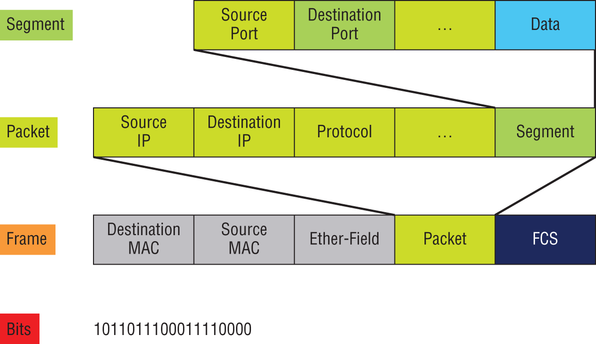
FIGURE 6.22 PDU and layer addressing
Remember that a data stream is handed down from the upper layer to the Transport layer. As technicians, we really don't care who the data stream comes from because that's a programmer's problem. Our job is to rebuild the data stream reliably and hand it to the upper layers on the receiving device.
Before we go further in our discussion of Figure 6.22, let's review port numbers and make sure you understand them. The Transport layer uses port numbers to define both the virtual circuit and the upper-layer process, as you can see from Figure 6.23.
The Transport layer takes the data stream, makes segments out of it, and establishes a reliable session by creating a virtual circuit. It then sequences (numbers) each segment and uses acknowledgments and flow control. If you're using TCP, the virtual circuit is defined by the source port number. Remember, the host just makes this up starting at port number 1024 (0 through 1023 are reserved for well-known port numbers). The destination port number defines the upper-layer process (application) that the data stream is handed to when the data stream is reliably rebuilt on the receiving host.
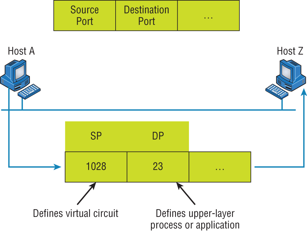
FIGURE 6.23 Port numbers at the Transport layer
Now that you understand port numbers and how they're used at the Transport layer, let's go back to Figure 6.22. Once the Transport layer header information is added to the piece of data, it becomes a segment and is handed down to the Network layer along with the destination IP address. (The destination IP address was handed down from the upper layers to the Transport layer with the data stream, and it was discovered through a name resolution method at the upper layers—probably DNS.)
The Network layer adds a header and also the logical addressing (IP addresses) to the front of each segment. Once the header is added to the segment, the PDU is called a packet. The packet has a protocol field that describes where the segment came from (either UDP or TCP) so it can hand the segment to the correct protocol at the Transport layer when it reaches the receiving host.
The Network layer is responsible for finding the destination hardware address that dictates where the packet should be sent on the local network. It does this by using ARP. IP at the Network layer looks at the destination IP address and compares that address to its own source IP address and subnet mask. If it turns out to be a local network request, the hardware address of the local host is requested via an ARP request. If the packet is destined for a remote host, IP will look for the IP address of the default gateway from its configuration information, then ARP for the hardware address of the default gateway (router) instead.
The packet, along with the destination hardware address of either the local host or default gateway, is then handed down to the Data Link layer. The Data Link layer will add a header to the front of the packet, and the piece of data then becomes a frame. (We call it a frame because both a header and a trailer are added to the packet, which makes the data resemble bookends or a frame, if you will.) This is shown in Figure 6.22. The frame uses an Ether-Type field to describe which protocol the packet came from at the Network layer. Now a CRC is run on the frame, and the answer to the CRC is placed in the FCS field found in the trailer of the frame.
The frame is now ready to be handed down, one bit at a time, to the Physical layer, which will use bit-timing rules to encode the data into a digital signal. Every device on the network segment will synchronize with the clock, extract the 1s and 0s from the digital signal, and build a frame. After the frame is rebuilt, a CRC is run to make sure the frame is okay. If everything turns out to be good, the hosts will check the destination address to see if the frame is for them.
If all this is making your eyes cross and your brain freeze, don't freak—things will become much clearer as we go through the book—really! Soon, I'll be going over exactly how data is encapsulated and routed through an internetwork in even more detail, in an easy-to-understand, step-by-step manner, in Chapter 9, “Introduction to IP Routing.”
Summary
Protocols, protocols everywhere—so many different reasons for them, and so many jobs they do for us! And sometimes they even work in conjunction with each other. This can seem like way too much information, but no worries—as you become familiar with the various layers and their functions, I promise it will soon become clear that this hierarchical structure is a seriously tight, robust networking foundation.
Similarly, as you understand the TCP/IP big picture, the reason why all these protocols exist and are necessary will also become much easier to understand. They're really like a team that works jointly, from layer to layer, to make our TCP/IP networks the wonderful, great tools they are.
Exam Essentials
- Remember the Process/Application layer protocols. Telnet is a terminal-emulation program that allows you to log into a remote host and run programs. File Transfer Protocol (FTP) is a connection-oriented service that allows you to transfer files. Trivial FTP (TFTP) is a connectionless file transfer program. Simple Mail Transfer Protocol (SMTP) is a sendmail program.
- Understand data encapsulation and decapsulation within the OSI model context. This includes Ethernet header and the Internet Protocol (IP) header, Transmission Control Protocol (TCP)/User Datagram Protocol (UDP) headers, TCP flags, Payload, and Maximum transmission unit (MTU).
- Be able to explain common ports and protocols, their application, and encrypted alternatives. Know all the protocol ports listed in the objectives for FTP, SSH, SFTP, and more.
- Be able to identify and define protocol types. This includes Internet Control Message Protocol (ICMP), TCP, UDP, Generic Routing Encapsulation (GRE), Internet Protocol Security (IPSec), Authentication Header (AH)/Encapsulating Security Payload (ESP).
- Remember the Host-to-Host layer protocols. Transmission Control Protocol (TCP) is a connection-oriented protocol that provides reliable network service by using acknowledgments and flow control. User Datagram Protocol (UDP) is a connectionless protocol that provides low overhead and is considered unreliable.
- Remember the Internet layer protocols. Internet Protocol (IP) is a connectionless protocol that provides logical network addressing and routing through an internetwork. Address Resolution Protocol (ARP) finds a hardware address from a known IP address. Internet Control Message Protocol (ICMP) provides diagnostics and Destination Unreachable messages.
Written Lab
Provide the answers to the following questions. You can find the answers in Appendix A.
- What would an ARP destination MAC address appear as?
- Name the protocol that uses both TCP ports 20 and 21.
- What Transport layer protocol does a DNS server use?
- Which protocol dynamically reports errors to source hosts by using IP directly to build packets?
- What could cause a server that you can ping to not provide the particular TCP/IP service, such as FTP, HTTP, and so on, that you expect it to offer?
- What is the well-known port number for RDP?
- Which ports does the protocol MGCP use?
- What protocol is at the heart of the
pingandtracertcommands in a Windows operating system? - Which destination Transport layer protocol and port number does a TFTP client use to transfer files over the network?
- What well-known port numbers do SMTP, POP3, RDP, and IMAP4 servers use?
Review Questions
You can find the answers to the review questions in Appendix B.
- The OSI model has seven layers and the DoD has four. At which layer does SMTP work in both models?
- Network
- Transport
- Session
- Application
- Internet
- You need to have secure communications using HTTPS. What port number is used by default?
- 69
- 23
- 21
- 443
- You want to implement a mechanism that automates the IP configuration, including IP address, subnet mask, default gateway, and DNS information. Which protocol will you use to accomplish this?
- SMTP
- SNMP
- DHCP
- ARP
- What protocol is used to find the hardware address of a local device?
- RARP
- ARP
- IP
- ICMP
- BootP
- You need to log in to a Unix/Linux server across a network that is not secure. Which of the following protocols will allow you to remotely administer this server securely?
- Telnet
- SSH
- SFTP
- HTTP
- If you can ping by IP address but not by hostname, or FQDN, which of the following port numbers is related to the server process that is involved?
- 21
- 23
- 53
- 69
- 80
- Which of the following describe the DHCP Discover message? (Choose two.)
- It uses FF:FF:FF:FF:FF:FF as a layer 2 broadcast.
- It uses UDP as the Transport layer protocol.
- It uses TCP as the Transport layer protocol.
- It does not use a layer 2 destination address.
- What layer 4 protocol is used for a Telnet connection, and what is the default port number?
- IP, 6
- TCP, 21
- UDP, 23
- ICMP, 21
- TCP, 23
- Which statements are true regarding ICMP packets? (Choose two.)
- They acknowledge receipt of a TCP segment.
- They guarantee datagram delivery.
- They can provide hosts with information about network problems.
- They are encapsulated within IP datagrams.
- They are encapsulated within UDP datagrams.
- Which of the following services use TCP? (Choose four.)
- DHCP
- SMTP
- SNMP
- FTP
- HTTP
- TFTP
- Which of the following services use UDP? (Choose three.)
- DHCP
- SMTP
- SNMP
- FTP
- HTTP
- TFTP
- Which of the following TCP/IP protocols are used at the Application layer of the OSI model? (Choose three.)
- IP
- TCP
- Telnet
- FTP
- TFTP
- Which of the following protocols is used by email servers to exchange messages with one another?
- POP3
- IMAP
- SMTP
- HTTP
- You need to have a connection to run applications that are installed on only your desktop computer at your office. Which protocol will provide a GUI interface to your work computer?
- Telnet
- FTP
- RDP
- IMAP
- SMTP
- Which of the following protocols can use TCP and UDP, permits authentication and secure polling of network devices, and allows for automated alerts and reports on network devices?
- DNS
- SNMP
- SMTP
- TCP
- You need to transfer files between two hosts. Which protocol can you use?
- SNMP
- RIP
- NTP
- FTP
- What layer in the IP stack is equivalent to the Transport layer of the OSI model?
- Application
- Host-to-Host
- Internet
- Network Access
- You need to make sure that the time is consistent across all your network devices. What protocol do you need to run on your network?
- FTP
- SCP
- NTP
- RTP
- Which of the following allows a server to distinguish among different simultaneous requests from the same host?
- They use different port numbers.
- A NAT server changes the IP address for subsequent requests.
- A server is unable to accept multiple simultaneous sessions from the same host. One session must end before another can begin.
- The MAC address for each one is unique.
- Which of the following uses both TCP and UDP?
- FTP
- SMTP
- Telnet
- DNS