
12
FUNDAMENTALS OF DATABASE
Contents
- Database
- File-oriented approach and database approach
- Characteristics of database approach
- Data models, schemas and instances
- Conceptual data model—Entity, attribute, relationship, and E-R model
- Representation data model—Hierarchical, network, relational data model
- Low level, or physical data model
- Database system
- Components of database system— Users, software, hardware, and data
- Architecture of database system—Internal level, conceptual level, and external level
- Database management system
- Data independence—Logical data independence, physical data independence
- Data dictionary, Database Administrator (DBA)
- Database languages—DDL, and DML
- Database system architectures—Centralized DBMS architecture, client-server architecture, and distributed database
- Database applications
Why this chapter
Computerized applications developed for personal use, for organizations and for enterprises, access, manipulate and manage the data. The data is stored in a database for easy access and retrieval. It is essential to have an understanding of the concepts of the database system to be able to manipulate the database and manage it properly. The purpose of this chapter is to introduce you to the fundamentals of the Databases.
12.1 INTRODUCTION
Databases and database systems are essential parts of our life. We have been interacting with non-computerized databases since long time, remember, looking for a word in a dictionary or finding the telephone number of your friend from a telephone directory. Computerized databases use computer to store, manipulate, and manage the database. In our daily lives we interact with the computerized databases when we go for the reservation of railway tickets and movie tickets, for the searching of a book in a library, to get the salary details, to get the balance of our account while using an ATM, to get the rate list while purchasing items from a cash and carry store and, this list can run into several pages. Lately, databases (Figure 12.1) are also used to store highly data intensive items like photographs (http://flickr.com), video clippings (http://YouTube.com), and images (http://images.google.co.in).
This chapter discusses the database approach and its advantage over the traditional file-based approach. The chapter describes the components of the database system and the various data models. A brief description of the architecture of the database system is also given. In the end, the chapter highlights the different types of database architecture and the database applications.
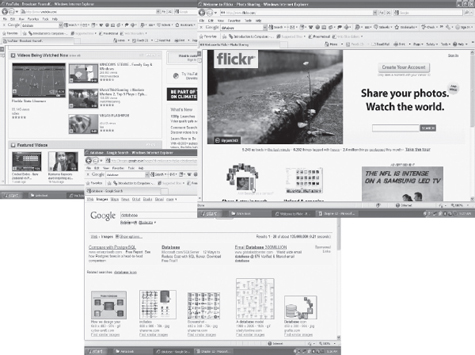
Figure 12.1 Databases
12.2 DATABASE
Database is a repository or collection of logically related, and similar data. Database stores similar kind of data that is organized in a manner that the information can be derived from it, modified, data added, or deleted to it, and used when needed. Some examples of databases in real life situations are: dictionary—a database of words organized alphabetically along with their meaning, telephone directory—a database of telephone numbers and addresses organized by the last name of people, railway timetable— a database of trains organized by train names, and, companies listed on Stock Exchange organized by names alphabetically.
A database is defined as—(1) a collection, or repository of data, (2) having an organized structure, and (3) for a specific purpose. A database stores information, which is useful to an organization. It contains data based on the kind of application for which it is required. For example, an airline database may contain data about the airplane, the routes, airline reservation, airline schedules etc.; a college database may contain data about the students, faculty, administrative staff, courses, results etc.; a database for manufacturing application may contain data about the production, inventory, supply chain, orders, sales etc.; and a student database may contain data about students, like student names, student course etc.
12.2.1 File-Oriented Approach and Database Approach
In the early days, data was stored in files. For an application, multiple files are required to be created. Each file stores and maintains its own related data. For example, a student information system would include files like student profile, student course, student result, student fees etc. The application is built on top of the file system. However, there are many drawbacks of using the file system, as discussed below—
- Data redundancy means storing the same data at multiple locations. In an application, a file may have fields that are common to more than one file. The data for these common fields is thus replicated in all the files having these fields. This results in data redundancy, as more than one file has the same data values stored in them. For example, student_name and student_course may be stored in two files—“student profile” and “student fees”.
- Data inconsistency means having different data values for the common fields in different files. During the updating process, the common fields may not get updated in all the files. This may result in different data values for the common fields in different files. For example, a student having different home address in two different files. Data redundancy provides opportunity for data inconsistency. Figure 12.2 shows data redundancy, and data inconsistency in two files.
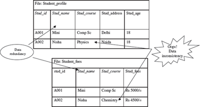
Figure 12.2 Data inconsistency and data redundancy
- The files in which the data is stored can have differentfile formats. This results in difficulty in accessing the data from the files since different methods are required for accessing the data from the files having different formats.
- In a file system, the constraints ofthe system (for example, student age >17) become part of the program code. Adding new constraints or changing an existing one becomes difficult.
- The files can be accessed concurrently by multiple users. Uncontrolled concurrent access may lead to inconsistency and security problems. For example, two users may try to update the data in a file at the same time.
Database approach provides solutions for handling the problems of the file system approach. The emergence of database approach has resulted in a paradigm shift, from each application defining and maintaining its own data (file-oriented approach)—to the data being defined and administered centrally (database approach). In the database approach, data is defined and stored centrally.
12.2.2 Characteristics of Database Approach
The main characteristics of the database approach are defined as follows:
- Data Redundancy is Minimized: Database system keeps data at one place in the database. The data is integrated into a single, logical structure. Different applications refer to the data from the centrally controlled location. The storage of the data, centrally, minimizes data redundancy.
- Data Inconsistency is Reduced: Minimizing data redundancy using database system reducesdata inconsistency too. Updating of data values becomes simple and there is no disagreement in the stored values. E.g. students’ home addresses are stored at a single location and get updated centrally.
- Data is Shared: Data sharing means sharing the same data among more than one user. Each user has access to the same data, though they may use it for different purposes. The database is designed to support shared data. Authorized users are permitted to use the data from the database. Users are provided with views of the data to facilitate its use. E.g. the students’ home addresses stored in the database which is shared by student profile system and library system.
- Data Independence: It is the separation of data description (metadata) from the application programs that use the data. In the database approach, data descriptions are stored in a central location called the data dictionary. This property allows an organization’s data to change and evolve (within limits) without changing the application programs that process the data.
- Data Integrity is Maintained: Stored data is changed frequently for variety of reasons such asadding new data item types, and changing the data formats. The integrity and consistency of the database are protected using constraints on values that data items can have. Data constraint definitions are maintained in the data dictionary.
- Data Security is Improved: The database is a valuable resource that needs protection. The data base is kept secure by limiting access to the database by authorized personnel. Authorized users are generally restricted to the particular data they can access, and whether they can update it or not. Access is often controlled by passwords.
- Backup and Recovery Support: Backup and recovery are supported by the software that logs changes to the database. This support helps in recovering the current state of the database in case of system failure.
- Standards are Enforced: Since the data is stored centrally, it is easy to enforce standards on the database. Standards could include the naming conventions, and standard for updating, accessing and protecting data. Tools are available for developing and enforcing standards.
- Application Development Time is Reduced: The database approach greatly reduces the cost and time for developing new business applications. Programmer can focus on specific functions required for the new application, without having to worry about design, or low-level implementation details; as related data have already been designed and implemented. Tools for the generation of forms and reports are also available.
In addition to the advantages highlighted above, there are several other implications of using the database approach like provision of multiple-user interfaces, representation of complex relationships, concurrent data access etc.
There are, however, some disadvantages of database systems over the file-based systems. The database systems are more vulnerable than file-based systems because of the centralized nature of a large integrated database. If a failure occurs, the recovery process is more complex and sometimes may result in lost transactions.
12.2.3 Data Models, Schema and Instances
The information stored inside a database is represented using data modeling. The data model describes the structure of the database. A data model consists of components for describing the data, the relationships among them, and the semantics of data and the constraints that hold data. Many data models exist based on the way they describe the structure of database. The data models are generally divided into three categories as follows:
- High level or conceptual Data Model,
- Representation or implementation Data Model, and
- Low level or physical Data Model
Schema is the logical structure of the database. A schema contains information about the descriptions of the database like the names of the record type, the data items within a record type, and constraints. A schema does not show the data in the database. The database schema does not change frequently.
Instances are the actual data contained in the database at a particular point of time. The content of the database may change from time to time.
12.2.4 High-Level or Conceptual Data Model
The conceptual data model is a description of the data requirements of the user. This model is not concerned with the implementation details. It ensures that all the functional and data requirements of the users are specified, conceptually. The conceptual model is defined using terms like (1) Entity, (2) Attribute, and (3) Relationship. The Entity-Relationship model (E-R model) is an example of conceptual data model. The following subsections, briefly describe these terms and the E-R model.
12.2.4.1 Entity
An entity is the basic unit for modeling. It is a real-world object that exists physically or conceptually. An entity that exists physically is a tangible object like student, employee, room, machine, part or supplier. An object that exists conceptually is a non-tangible object like an event or job title. For e.g. student information system may consist of entities like student_profile, marks and course. A set of entities of the same type having same properties, or attributes is defined as an entity set. For example, a set of all persons who are students of the university can be defined as an entity set student. Likewise, the entity set course may represent a set of all courses offered by a University. An entity set is usually referred to by the same name as an entity. For example, Student is an entity set of all student entities in the database. Diagrammatically, an entity is represented using a rectangle. Figure 12.3 shows the entities for a database created in MS-Access 2007.
12.2.4.2 Attribute
An attribute describes some property or characteristics of the entity. For e.g. student name, student address, and student age are attributes of the entity student_profile. An attribute ensures that similar information is stored about each entity in an entity set, in the database. However, each attribute of an entity may have its own value. The set of permitted values for an attribute is called the domain of the attribute. For example, the domain of the attribute student name is text string, or, the domain of student age is a positive integer ranging between 18 and 65. Diagrammatically, an attribute is represented as an ellipse connected to the entity with a line. Figure 12.3 shows the attributes for the entity “Employee” in MS-Access 2007.
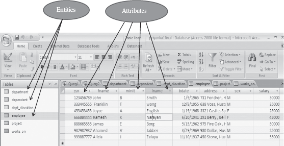
Figure 12.3 Entities and attributes
12.2.4.3 Relationship
An association or link between two entities is represented using a relationship. A set of relationships of the same type form a relationship set. For e.g. “student enrolls in course” is a relationship set between the entities student and course. Cardinality ratio is the number of entities to which another entity gets associated in a relationship set. The cardinality ratio of a relationship set is any one of the four kinds—(1) One-to-One, (2) One-to-Many, (3) Many-to-One, and (4) Many-to-Many. In two entity sets A and B, the different cardinality ratio imply the following:
- One-to-One: An entity in A is associated with at most one entity in B and vice versa.
- One-to-Many: An entity in A is associated with any number of entities in B, but an entity in B is associated with at most one entity in A.
- Many-to-One: An entity in A is associated with at most one entity in B, but an entity in B is associated with any number of entities in A.
- Many-to-Many: An entity in A is associated with any number of entities in B and vice versa.
Diagrammatically, a relationship is represented using a diamond connected to the entity by a line. Figure 12.4 shows the different kinds of relationships.
12.2.4.4 Entity-Relationship (E-R) Model
E-R model is a model of the real world. E-R model represents the entities contained in the database. The entities are further described in the database using attributes. The relation between the entities is shown using the relationships. The model also shows the cardinality constraints to which the database must adhere to. The E-R model is represented diagrammatically using an E-R diagram. Figure 12.5 shows a simple E-R diagram. The diagram shows two entities—Student and Course. The Stud_Name and Stud_RollNo are the attributes of the entity Student. The Course_Id and Course_Name are the attributes of the entity Course. The Admission relationship associates the student with the course. Database design in E-R model is converted to design in the Representation Model which is used for storage and processing.
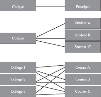
Figure 12.4 Relationships (a) One-to-one (b) One-to-many (c) Many-to-many
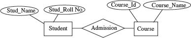
Figure 12.5 E-R diagram
Object-Oriented (OO) database model use object-oriented programming. The object data model defines a database in terms of objects, classes, and methods. It is beneficial in web applications, and in specialized application areas like multimedia, manufacturing system, and engineering design, and for the storing of multimedia objects.
12.2.5 Representation or Implementation Data Model
The Conceptual Data Model is transformed into the Representation Data Model. Representation data model uses concepts that are understood by the end-user and are also close to the way the data is organized in the computer. These models hide the details of data storage. The data models are broadly classified as traditional data models that include—(1) hierarchical, (2) relational, and (3) network data models. Object-relational data model is an emerging data model.
12.2.5.1 Relational Database Model
The Relational Database Model was proposed in 1970 by E. F. Codd. The first commercial system based on the relational model became available in early eighties. Relational database model is the most common type of database model. Table, record, field, key, and data values are the terms associated with a relational model. The data elements are stored in different tables made up of rows and columns. The data in different tables are related through the use of common data elements. We briefly define the terms as follows—

Figure 12.6 Table “Employee”
- Data Values Data values are the raw data represented in numeric, character, alphanumeric, or alphabetic form. Examples of data values are ‘Abhinav Bindra’, ‘26’ ‘shooting’, “Chandigarh” etc.
- Field or Column Data values or data is stored in a database as fields. For an item or object, a field holds the information of it. For example, individual fields or columns are name, age, address, hobby etc. for an object ‘student profile’.
- Record or Row A group of data for related field is called a record. For example, for object ‘student profile’, the related fields are (name, age, address, and hobby). The data about the student #1 (‘Abhinav Bindra’, 26, ‘Chandigarh’, and ‘Shooting’) is one record.
- Table A collection of logically related records form a table. A table for an object has rows and columns. The table is organized as a set of columns, and can have any number of rows. For example a table for student profile can have four columns namely, name, age, address, and hobby, and have records or rows having data of 30 students.
- Key A key is an identifier in a table that uniquely identifies a row in a table. The key identifier can be the value of a single column or of multiple columns. A key is generally also referred to as the primary key of the table. The primary key is a unique identifier for the table. The column or combinations of columns that form the primary key have unique values. At any time, no two rows in the table can have same values for the primary key. For example, in a student table, each student has a unique student_rollno, which forms the primary key.
In its simplest form, a database may contain a single table stored as a file. In more complex databases, a collection of related tables may be stored together. For example, a student database may contain a table for student profile, student result, student courses etc. Figure 12.6 shows a table “Employee”, with fields, records, data values & primary key.
Several commercial products like DB2, ORACLE, SQL Server, SYBASE, and INFORMIX are relational databases. The Relational Data Model is extended to include the object database concepts thus forming the Object-Relational Data Model.
12.2.5.2 Hierarchical Database Model
The Hierarchical DatabaseModel was developed by IBM and is the oldest database model. The hierarchical database model is defined as follows—
- The schema of a hierarchical database is represented using a Sree-structure diagram (Figure 12.7).
- The nodes of the tree represent a record type. A line connecting two nodes represents the link.
- The schema is based on parent-child relationship.
- A parent can have none, one, or more children. A child can have only one parent.
- The parent-child relationship is suited for the modeling of one-to-many relationship between two entities.
- It is difficult to implement a many-to-many relationship using hierarchical database model.
- Some of the hierarchical database implementations are the IMS system from IBM and System 2000 from MRI systems.

Figure 12.7 Hierarchical database model
12.2.5.3 Network Database Model
The Network Database Model was formalized by DataBase Task Group (DBTG) group of Conference on Data Systems Languages (CODASYL) in the late 1960s. The Network Database Model is defined as follows:
- The schema of the network database model is represented using a data-structure diagram.
- The boxes represent the record type and the lines represent the links (Figure 12.8).
- The schema is based on owner-member relationship.
- The entity type is represented using record type and relationship between entities is represented using set type.
- A set type can have more than one record type as a member but only record type is allowed to be the owner in a set type.
- The owner-member relationship is suited to represent one-to-many relationships. The one-to-many relationship is converted into a set of one-to-one relationships.
- The network model handles many-to-many relationship by converting it into two or more one-to-many relationships.
- Some of the network database implementations are IDMS, DMS 1100 and IMAGE.
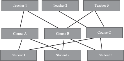
Figure 12.8 Network database model
The hierarchical model is simple to construct. However, the network model is able to handle complex relationships easily. Both hierarchical and network models are also called Segacy models as most current systems support the Relational Model.
12.2.6 Low-Level or Physical Data Model
The Physical Data Model describes the internal storage structures, the access mechanism, and the organization of database files. Physical level describes how a record (e.g., customer) is stored. Sequential files, direct files, and indexed sequential files are the different types of file organizations at the physical level.
12.3 DATABASE SYSTEM
A bank, hospital, college, university, manufacturer, government are some examples of organizations or enterprises that are established for specific purposes. All organizations or enterprises have some basic common functions. They need to collect and store data, process data, and disseminate data for their various functions depending on the kind of organization. Some of the common functions include payroll, sales report etc.
A database system integrates the collection, storage, and dissemination of data required for the different operations of an organization, under a single administration. A database system is a computerized record keeping system. The purpose of the database system is to maintain the data and to make the information available on demand.
12.3.1 Components of Database System
A database system has four main components—(1) Users, (2) Hardware, (3) Software, and (4) Data.
- Users Users are the people who interact with the database system. The users of a database system are segregated into three categories based on the way they interact with the system— (1) Application Programmers, (2) End Users, and (3) Data Administrators.
- Application programmers develop application programs that manipulate the database. The developed application programs operate on the data for its insertion, deletion and retrieval. Programs are also written for interacting with the system through calls, accessing of specialized database applications, creating form requests etc.
- End users are the people who interact with the database system to get information from the database to carry out their business responsibility. They interact with the system through menus or forms. These users can also interact with the system using query languages which requires some expertise for its use. End users include people like executives, managers, clerical staff, bank teller, and so on.
- Data administrator is the manager responsible for establishing policies for the maintenance and handling of data once it is stored. The creation of database and the implementation of policies of the data administrator is a technical task, which is performed by a technical person called the Data Base Administrator (DBA). While the Data administrator’s role is managerial in nature, the DataBase Administrator’s role is technical in nature.
- Software In a database system, software lies between the stored data and the users of data. The database software can be broadly classified into three types—(1) DataBase Management System (DBMS), (2) Application software, and (3) User Interface.
- DBMS handles requests from the users to access the database for addition, deletion, or retrieval of data. Software components required to design the DBMS are also included here. Some software components are the automated tools like Computer-Aided Software Engineering (CASE) tools for the designing of databases and application programs, software utilities, and report writers.
- Application software uses DBMS facilities to manipulate the database to achieve a specific business function, such as, providing reports that can be used by users. Application software is generally written in a programming language like C, or it may be written in a language supported by the DBMS.
- User interface of the database system constitutes the menus and the screens that the user uses to interact with the application programs and the DBMS.
- Hardware Hardware is the physical device on which the database system resides. The hardware required for the database system is the computer or a group of connected computers. Hardware also includes devices like magnetic disk drives, I/O device controllers, printers, tape drives, connecting cables and other auxiliary hardware.
- Data Data is raw numbers, characters, or facts represented by values. The data can be numeric data, non-numeric data, images or pictures. Some examples of data are 23, 45, “Divya”, “Computer”, “India”. The data in a database system is integrated and shared.
- Integrated data implies that several distinct data files are unified in a manner that redundancy among these data files is wholly or partially eliminated. For example, a database may contain files for STUDENT_PROFILE having student roll no., student name, address, course enrolled etc., and MARKS file having the marks of students in various subjects. To prepare the report card, there is a need to get the complete student profile along with the marks obtained in each subject. For this, the complete profile of the student need not be stored in MARKS file as the information can be retrieved by referring to STUDENT_PROFILE file.
- Shared data implies that the data stored in the database can be shared among multiple users, such that each user has access to the same data, which the user can use for different purposes. For example, data for course enrolled in STUDENT_PROFILE file is shared by the NCC department and the Library department—both use the same data for different purposes.
12.3.2 Architecture of Database System
The architecture of a database system provides a general framework for database systems. Different database systems, small or big, may not support all aspects of the architecture; however, different systems can be matched to the framework. The architecture for database system is proposed by ANSI/SPARC study group and is called ANSI/SPARC architecture. The purpose of the architecture is to make databases more independent of the application that is using the database. Schema contains information about the description of the database.
The ANSI/SPARC architecture is divided into three levels (Figure 12.9), as follows:
- Internal (Physical) Level has an internal schema. The internal schema describes the physical storage structure of the database. It is concerned about how data is stored physically. It does not deal with the physical storage in terms of blocks, neither pages nor the device. Rather, it describes the organization of files, the access path to the database etc. The physical data model is used to describe the physical schema.
- Conceptual Level has a conceptual schema. The conceptual schema describes the structure of whole database for the users. It describes the entities in the database, their relationships, and constraints. The representation or implementation data model is used to describe the conceptual schema. Conceptual schema also uses the conceptual data model.
- External Level or View Level provides a user’s and application’s view of the data. It includes one or more external schema. For a particular user, the external schema describes the structure of the database relevant to it, and hides rest of the information. It uses the data model at the conceptual level.
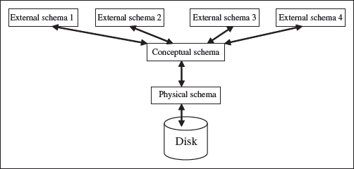
Figure 12.9 Three schema architecture
12.4 DATABASE MANAGEMENT SYSTEM
The interrelated set of data that forms the database needs to be stored and managed, so that the database can be accessed for the retrieval of data, and for insertion, deletion, or updating of data. DBMS is a software system for creating, organizing and managing the database. DBMS handles all access to the database and manages the database. Managing the database implies that it provides a convenient environment to the user to perform operations on the database for creation, insertion, deletion, updating, and retrieval of data. DBMS defines the scope of the use of database. This keeps data secure from unauthorized access. The functionality of DBMS includes—(1) the database that contains interrelated data, and (2) a set of programs to access the data. The DBMS implements the three schema architecture—internal schema at internal level, conceptual schema at conceptual level, and external schema at external level. The different DBMSs may not provide a clean distinction between the three levels, but generally they follow the three schema architecture.
Mappingis a term used for transforming requests and the results between different levels of the DBMS architecture. In a DBMS, the user interacts with the DBMS through the external view, and the data in the DBMS is stored at the physical level. Any request from the user, would require that the DBMS access the data and then present it to the user as specified in the external schema. This requires transforming the request from one level to the other, or mapping.
Some of the common commercial DBMSs are—Oracle Database, IBMs DB2, Microsoft’s SQL Server and Microsoft Access. MySQL is a popular open source DBMS.
12.4.1 Data Independence
Data independence is defined as the ability to change a schema at one level without affecting the schema at another level. The mapping from the external level to conceptual level and from the conceptual level to the physical level provides two types of data independence—Logical Data Independence and Physical Data Independence.
- Logical Data Independence. is the ability to modify the conceptual schema without resulting in a change in the external schema. The changes made to the conceptual schema may be like adding a record, adding a data item, updating constraints etc. The logical data independence is facilitated by providing a view of the conceptual database at the external level. At the external level, the user is interested in the portion of the database that represents its external view. The database system provides a mapping from the external view to the conceptual view. Many different external views may exist, but there is only one conceptual view.
- Physical Data Independence is the ability to modify the physical schema without changing the conceptual schema. The changes at the physical level could be like reorganization of files, improved access methods, change in physical storage devices etc. The physical data independence is facilitated by the database system by providing a mapping from the physical view to the conceptual view of the database.
The concept of data independence is similar to the concept of abstract data types in programming languages, where the interface is presented to user and the implementation details are hidden.
12.4.2 Data Dictionary
Data dictionary stores the data about the actual data stored in the database. Data dictionary contains metadata, i.e. data about the data. Metadata is the data that describe the properties or characteristics of other data. Some of these properties include data definitions, data structures and rules or constraints, the data item, the data type, length, minimum and maximum allowable values (where required) and a brief description of each data item. Metadata allow database designers and users to understand what data exist and what the data mean. Data dictionary keeps track of the following:
- Definitions of all data items in the database—It includes the elementary-level data items (fields), group and record-level data structures, and files or relational tables.
- Relationships that exists between various data structures,
- Indexes that are used to access data quickly, and
- Screen and report format definitions that may be used by various application programs.
12.4.3 Database Administrator (DBA)
DBA is a person or a group of persons who have centralized control of the database. DBA coordinates all activities of the database system. DBA has a good understanding of the database and of the needs and resources of the organization where it is installed. The DBA is responsible for creating, modifying and maintaining the three levels of DBMS architecture.
The functions of DBA include—(1) defining of schema, (2) defining of storage structure and access method, (3) modification of schema and physical organization, (4) granting user authority to access the database, and (5) acting as liaison with users, monitoring performance, and responding to changes in requirements.
12.4.4 Database Languages
In a DBMS, there is a need to specify the conceptual schema and the external schema. Once the schema is defined and data is filled in the schema, there is a need to manipulate the data, i.e. insertion, deletion, and modification of the data. For all these purposes, DBMS provides a set of languages— Data Definition Language (DDL), and Data Manipulation Language (DML). DDL is used by database designers for defining the database schema. DML is used for the manipulation of data. Structured Query Language (SQL) is a relational database language that represents a combination of both DDL and DML.
12.4.4.1 Data Definition Language (DDL)
DDL is a specification notation for defining the database schema. For example, a DDL command in SQL is as follows—
create table student (
stud_rollno char(10),
stud_name char(20),
stud_age integer)
The create table command creates a table named student having three fields—stud_rollno of type character and size 10, stud_name of type character and size 20, and stud_age of type integer.
The DBMS has a DDL compiler which processes the DDL statements and generates a set of tables which are then stored in a data dictionary.
12.4.4.2 Data Manipulation Language (DML)
DML is a query language for accessing and manipulating the data stored in database. Data Manipulation Languages are of two main types—procedural, and non-procedural language. In a procedural language, user specifies both the data that is required and how to retrieve that data. The procedural language is embedded into a general-purpose programming language. However, in a non-procedural language, user specifies only what data is required without specifying how to retrieve the data. SQL is the most widely used non-procedural query language. For example, the SQL query to find name of the student having roll no A121, in the table student is—
select student.stud_name
from student
where student.stud_rollno = ‘A121’
The DML commands (Figure 12.10) when used in a standalone interactive manner is called the query language.
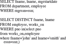
Figure 12.10 DML commands
12.5 DATABASE SYSTEM ARCHITECTURES
The computers has evolved from big mainframe computers to small desktop personal computers. The advances in computer and its architecture have also resulted in the advances in databases and its architecture. Here, we discuss the architecture of databases of three kinds—Centralized DBMS Architecture, Client-Server Architecture, and Distributed Databases.
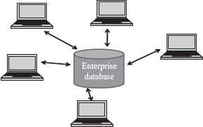
Figure 12.11 Centralized database
12.5.1 Centralized DBMS Architecture
- Centralized databases are the traditional database systems where all database functionality, data, application program and user interface processing are located on one machine. Access to the database from remote locations is via the communication links (Figure 12.11).
- In the early systems, the mainframe computers provided all the functionality required by the users of computer. The users interacted with the mainframe computers via dumb terminals. All processing was performed on the mainframe computer. The DBMS was centralized, and stored on the mainframes. The dumb terminals had only the display facility.
- The centralized database is easy to manage and administer.
- Common examples of centralized databases are personal database, and central computer database.
12.5.2 Client-Server Architecture
- The growth of Personal Computer (PC) has resulted in PCs replacing the dumb terminals. PCs are powerful and fast machines that can handle the user interface functionality.
- Client-Server systems involve a client machine and a server machine. Clients are PCs or workstations that have user interface capability and functionality for local processing. Servers are powerful computers that can manage the files (file servers), printer (printer servers), or, e-mails (e-mail servers). The client is connected to the server via a communication link. The client interacts with the server when it requires access to any additional functionality that does not exist in its own machine. Client provides interfaces to access and utilize the server resources.
- The Client-Server architecture has three components—the user interface programs, the application programs that contain the application logic, and the DBMS that stores the data. The request made by the user interface program is processed using the application logic which then accesses the database to retrieve the data.
- The DBMS architecture on the Client-Server systems are of two kinds—two-tier Client-Server architecture and three-tier Client-Server architecture.
- In two-tier Client-Server architecture, the user interface programs and the application programs run on the client side. An Application Program Interface (API) allows client side programs, to call the DBMS which is at the server side. The client programs use Open Data Base Connectivity (ODBC) or Java Data Base Connectivity (JDBC) interfaces to communicate with the database.
- The three-tier Client-Server architecture is commonly used for web applications. In addition to the client and the database servers, it has an intermediate layer or middleware called Application Server or Web Server. The web server stores the application or business logic part of the application. The client stores the user interface. The DBMS is stored at the server side. The web server interacts with client at one end, and with the server for the DBMS at the other end. The web server acts like a pipe for receiving the client request, processing it and accessing the data from the DBMS server, and sending it back to the client. Figure 12.12 shows the two-tier and three-tier Client-Server architecture.

Figure 12.12 Client-server architecture (a) 2-Tier (b) 3-Tier
12.5.3 Distributed Databases
- A distributed database is one with decentralized functionality of the DBMS. It is distributed among a number of computers (Figure 12.13).
- The computers that store the components of database are physically placed at different geographical locations; however, all the components are logically related.
- Access to the distributed databases is from remote locations via the communication links.
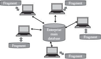
Figure 12.13 Distributed databases
12.6 DATABASE APPLICATIONS
Databases range from those designed for a single user with a desktop computer to those on mainframe computers with thousands of users. The database applications can be for different purposes like—(1) personal databases that support one user with a stand-alone personal computer, (2) workgroup databases for a small team of people (less than 25) who work in collaboration on a project, (3) departmental databases designed to support the various functions and activities of a department (a functional unit of an organization), and (4) enterprise databases to support organization-wide operations and decision making. Data warehouse is an enterprise database.
The DBMS commonly provides tools to the application programmer for application development. Some of the tools provided by DBMS include tools for screen, menu, and report generation, application generators, compilers, and data and view definition facilities. Modern database systems provide language components that are much more powerful than those of traditional languages. For example, Developer 2000/PowerBuilder for Oracle, and Visual Basic for Microsoft SQL server.
SUMMARY
- Database is a repository or collection of logically related and similar data.
- The file-oriented approach has several drawbacks. Database approach provides solutions for handling the problems of the file system approach.
- The characteristics of database approach include— minimized data redundancy, reduced data inconsistency, data sharing, data independence, integrated data, improved data security, backup and recovery support, standards enforcement, and reduction in application development time.
- A data model describes the structure of database. Schema contains information about the description of database. Instances are the actual data contained in database.
- Conceptual Data Model, Representation Data Model and Physical Data Model are the three types of data models.
- Conceptual Data Model defines the functional requirements and data requirements of user, conceptually, using entity, attribute, and relationship. E-R model is a conceptual data model.
- An entity is a real-world object that exists physically or conceptually.
- An attribute describes some property, or characteristics of the entity.
- An association or link between two entities is represented using a relationship.
- Hierarchical, relational, and network data models are the three representation data models.
- Table, row, column, key and data values are the terms associated with a relational model. A table is made up of rows and columns. A key uniquely identifies a row in a table.
- The schema of a hierarchical database model is represented using a tree-structure diagram. The schema is based on parent-child relationship.
- The schema of network database model is represented using a data-structure diagram. The schema is based on owner-member relationship.
- The physical data model describes internal storage structures, access mechanism, and organization of the files of database.
- A database system integrates collection, storage and dissemination of data required for the different operations of an organization.
- Users, Hardware, Software, and Data are the four main components of a database system.
- The architecture of database system is ANSI/SPARC architecture, divided into three levels—internal schema describes the physical storage structure, conceptual schema describes the structure of whole database for users, and external schema provides a user’s or application’s view of the data.
- DBMS is a software system for creating, organizing and managing the database.
- Data independence is the ability to change a schema at one level without affecting the schema at another level. Data independence is logical data independence and physical data independence
- Data dictionary keeps track of the definitions of data items in the database, relationships between data structures, indexes used to access data, and, screen and report format definitions.
- DBMS provides a set of languages—DDL, and DML. DDL is used to define the database schema. DML is a query language for accessing and manipulating data stored in the database.
- SQL is a relational database language that represents a combination of both DDL and DML.
- The architecture ofdatabases is of three kinds—Cen-tralized DBMS architecture, Client-Server architecture and Distributed Databases.
- The three-tier Client-Server architecture is commonly used for web applications. The client stores the user interface. The web server stores the business logic part of the application. The DBMS is at the server side.
- The database applications are for different purposes like personal databases, workgroup databases, departmental databases, and enterprise databases.
KEYWORDS
Application Programmers |
Data inconsistency |
Instances |
Application software |
Data Independence |
Integrated data |
Attribute |
Data Integrity |
Internal (Physical) Level |
Backup and Recovery |
Data Manipulation Language |
Key |
Cardinality Ratio |
(DML) |
Logical Data Independence |
Centralized architecture |
Data Models |
Low-level Data Model |
Client-Server Architecture |
Data redundancy |
Mapping |
Conceptual Data Model |
Data Security |
Network Database Model |
Conceptual Level |
Data sharing |
Owner-member |
Data |
Data Values |
Parent-child |
Database |
Distributed Databases |
Physical Data Independence |
Database administrator |
Domain |
Primary key |
Database Administrator |
End-Users |
Record or Row |
(DBA) |
Entity |
Relational Database Model |
Database Approach |
Entity set |
Relationship |
Database Architecture |
E-R Model |
Schema |
Database Management System |
External (View) Level |
Shared data |
(DBMS) |
Field or Column |
Software |
Database system |
File-Oriented Approach |
Structured Query Language |
Data Definition Language |
Hardware |
(SQL) |
(DDL) |
Hierarchical Database |
Table |
Data dictionary |
Implementation Data Model |
User Interface |
QUESTIONS
Section 12.2—12.2.2
1. Define: (1) Database, (2) Data redundancy, (3) Data consistency, and (4) Data Sharing.
2. List the differences between file-oriented approach and database approach.
3. List the characteristics of the database approach.
4. Explain the characteristics of database approach.
5. “Data redundancy provides opportunity for data inconsistency”. Explain.
Section 12.2.3—12.2.4.4
6. Define: (1) Data model, (2) Schema, (3) Instance, (4) Entity, (5) Attribute, (6) Domain of attribute, and (7) Cardinality Ratio.
7. How are entity and attribute related?
8. Explain the different kinds of cardinality ratios.
9. Name the symbols used to represent (1) entity, (2) attribute, and (3) relationship in an E-R diagram.
10. Give an example of conceptual data model.
11. What is an E-R diagram?
Section 12.2.5–12.2.5.1
12. Name the different types of representation data models.
13. Who proposed the Relational Data Model?
14. How are the terms table, record, field, key, and data values related?
15. What is the purpose of the key in relational data model?
16. Name two commercial relational databases.
17. What is a primary key?
18. Define the terms: (1) table, (2) record, (3) field, (4) key, and (5) data values.
Section 12.2.5.2–12.2.6
19. Describe the features of Hierarchical Data Model.
20. The schema of a hierarchical database is represented using a diagram.
21. The schema of hierarchical database is based on_ relationship.
22. Name one commercial hierarchical database.
23. The hierarchical database model was developed by_
24. The schema of network database model is represented using a_ diagram.
25. The schema of network database is based on relationship
26. Describe the features of Network Data Model.
27. Name one commercial network database.
28. What is the purpose of Physical Data Model?
Section 12.3–12.3.2
29. Define a database system.
30. List the components of database system.
31. Explain in detail the components of database system.
32. Explain the role of different categories of users in a database system.
33. What is the purpose of application software and user interface software in the database system?
34. “The data in a database system is integrated and shared”. Explain.
35. Name the three levels of ANSI/SPARC architecture.
36. What is the purpose of internal level, conceptual level and external level in the ANSI/SPARC architecture?
37. Explain the three schema architecture of database system in detail.
Section 12.4–12.4.4.2
38. Define: (1) DBMS, (2) Mapping, and (3) Data independence.
39. What is the need of mapping in a DBMS?
40. Name two commercial DBMS software.
41. What is logical data independence?
42. What is physical data independence?
43. Define a data dictionary.
44. Explain the function of data dictionary.
45. What are the functions of DBA?
46. What is the need of database languages?
47. DBMS provides two database languages_ and_
48. What is the use of DDL?
49. What is the use of DML language?
50. What is a Structured Query Language?
Section 12.5
51. What is a centralized DBMS architecture?
52. Explain the client-server architecture.
53. How is the two-tier client-server architecture different from the three-tier client-server architecture?
54. What are distributed databases?
55. Name some database applications.
Extra Questions
56. Give full form of the following abbreviations:
- DBMS
- DBA
- E-R Model
- DDL
- DML
- SQL
- ODBC
- JDBC
- CODASYL
- DBTG
- CASE
57. Write short notes on:
- Database System
- DBMS
- Components of
- Data Model database system
- Schema
- Data dictionary
- Conceptual data model
- Entity
- Attribute
- Key
- E-R model
- Hierarchical model
- Database
- Network model Applications
- Relational model
- Database Architecture
- Data independence
- Client-Server Architecture
- Database Administrator
- Database Languages
58. Give differences between the following:
- Logical Data Independence and Physical Data Independence
- DDL and DML
- Centralized databases and Distributed databases
- Internal Level and Conceptual Level
- Hierarchical, Network and Relational data models
- Conceptual data model and Representation data model
- File-Oriented Approach and Database Approach
- 2-Tier and 3-Tier Client-Server architecture