11
Vensim and the Development of System Dynamics
Lee Jones
Director, Ventana Systems UK, Oxton, Merseyside, UK
11.1 Introduction
This chapter does not dwell on the early history of system dynamics and the software used for implementation, since there are many respectable sources describing the origins and use of the early software programs such as Dynamo, Dysmap and their derivatives. This chapter is written from a personal perspective and includes anecdotal evidence from a number of unnamed but possibly respectable sources. Any errors or omissions are likely to be as a result of failing memory and/or fanciful wishful thinking.
In determining the content of this chapter, a causal loop diagram (CLD) was created as a sort of road map during its initial drafts and was continually updated as the drafts were reviewed and improved. It has been reproduced as Figure 11.1 in the hope that it will help to explain further the concepts described in the chapter, at the risk of exposing the author's potentially flawed thought-processes. It is incomplete, for example it does not include influences on ‘actual SD use’ other than the size of the pool of practitioners, but it serves to explain the narrative developed within the chapter.
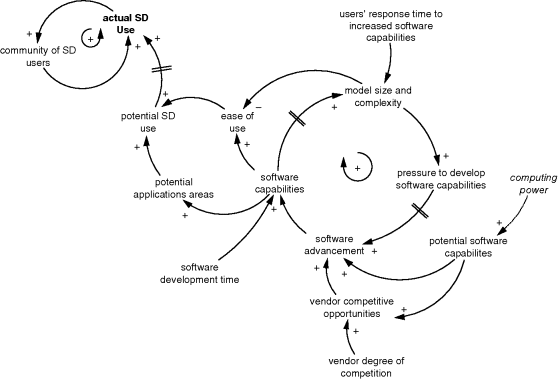
Figure 11.1 Chapter ‘map’.
11.2 Coping with Complexity: The Need for System Dynamics
The quote below is from a short story by the British science fiction writer Iain M. Banks. In this story, an advanced alien civilisation sends a small team of scientists to observe 1970s' Earth and the quote is part of a conversation between the star ship ‘mind’ (a super-intelligent sentient artificial intelligence or AI) and one of its crew. They discuss the merits, or otherwise, of intervening in human life on the planet (making ‘contact’) and the AI's observation below seems to capture the current state of affairs; system dynamicists are in the process of attempting to simplify complex systems in order to aid understanding. This would not go down too well with the ship ‘mind’ but, until we have super-intelligent AIs, one has at least to try!
I'm not sure that one approach could encompass the needs of their different systems. The particular stage of communication they're at, combining rapidity and selectivity, usually with something added to the signal and almost always with something missed out, means that what passes for truth often has to travel at the speed of failing memories, changing attitudes and new generations. Even when this form of handicap is recognised all they ever try to do, as a rule, is codify it, manipulate it, tidy it up. Their attempts to filter become part of the noise, and they seem unable to bring any more thought to bear on the matter than that which leads them to try and simplify what can only be understood by coming to terms with its complexity.
(Banks, 2010)
In a 2010 IBM Global Services survey (IBM, 2010) of 1541 chief executive officers in 60 countries and 33 industries (face-to-face conversations), 79% anticipated greater complexity ahead and defined the ‘new economic environment as being distinctly different’, characterised by being:
- More volatile; deeper/faster cycles, more risk.
- More uncertain; less predictable.
- More complex; multifaceted, interconnected.
- Structurally different; sustained change.
IBM identified three strategies employed by ‘standout’ organisations:
- Embody creative leadership.
- Reinvent customer relationships.
- Build operating dexterity.
From these strategies a number of recommendations were made and some of the language used in the body of the report is enough to warm the heart of any system dynamics practitioner: ‘reach beyond silos’, ‘encourage experimentation at all levels’, ‘lead by working together towards a shared vision’, ‘predict & act, not sense & respond’. Moreover, some recommendations have a remarkable synergy with system dynamics:
- Put complexity to work for your stakeholders:
- With improved insight into customers, processes and business patterns, drive better real-time decisions and actions throughout the enterprise.
- Take advantage of the benefits of analytics:
- Identify, quantify and reduce systemic inefficiencies.
- Elevate analysis from a back-office activity.
- Act quickly:
- Make decisions when you ‘know enough’ not when you ‘know it all’.
- Push execution speed:
- Rapid decision making and execution.
- Course-correct as needed:
- Align metrics with objectives and track results as part of a continuous feedback loop. Modify actions based on what is learned.
There is, however, not one mention of system dynamics (SD), simulation, modelling or systems thinking in the entire report and one would think that if IBM had indeed recommended SD, the CEO readership would have taken notice. How long their interest would have held is up for debate; what would they have found having tasked their internal strategy team to research this apparently new field of analytics? There are a number of published success stories when it comes to the application of SD in the realms of public policy, less so for successful implementation by consultants in business. A lack of transparency and excess of secrecy may account for some, but it is painfully obvious that SD has yet to gain enough traction to become the analytical tool of choice, much to the frustration of many in the field. And when SD does have its opportunity to shine, it is oftentimes let down by poor implementation, the product of insufficient investment in time by the potential user and an inability of many practitioners to ensure the successful application of sometimes excellent and innovative models. Once these opportunities are squandered, they affect the immediate future of SD within the specific industry. For example, early use of SD in the UK military was often limited by high-level assumptions that the decision makers could not understand and so the approach became invalid in their eyes. This hit the reputation of SD within UK military circles for years.
SD is simple, open and intuitive. It does not depend on advanced mathematics, it is more powerful than the ubiquitous spreadsheet and it is more capable of addressing problems at the highest level of strategic impact. It is pretty much nailed on as the analytical tool of choice. So why is SD not used more widely? This has perplexed experienced practitioners for decades. But perhaps it should not. In 2001 during an internal marketing symposium for a global IT organisation, the head of marketing stated, with tongue only slightly in cheek, that most of its sales were conducted on the golf course with no company salespeople in sight! The decision to invest millions and sometimes tens of millions of dollars in what was basically a glorified database was being made on the premise that everyone else was doing it. This enormous impact of word of mouth and the fear of being left behind ensured the successful rollout of new and eye-wateringly expensive IT systems across the globe in a matter of a few years with arguably marginal impact on competitiveness. SD could and should benefit from a similar explosion of use but SD appears to fly under the radar, much like a stealth fighter, and is just as invisible.
There are likely many reasons for this paradox but this chapter will focus on one facet of the problem: the software has, until now, been unable to provide the support required to facilitate this leap from understudy to star of the show. There is a need for software vendors to enhance the capabilities of their platforms but in such a way as to make them more acceptable to all stakeholders; the practitioners need greater support in their quest to educate and convince their clients and the clients need greater support in their understanding of the methodology and in the practical application within their current or future business processes.
11.3 Complexity Arms Race
As recently as the early 1990s, models were being developed through the creation of files containing explicit handwritten equations with minimal syntax checking or automated support. Causal loop diagrams (CLDs) were hand-drawn on paper or, for the sophisticated, created using third-party diagramming tools such as Corel Draw (Corel Corporation, 2013) with manual diagram and model code coordination. Debugging a model involved printing out the code and, with the aid of the mk1 eyeball, scanning hundreds of line of levels, rates, auxiliaries and constants (see the example in Figure 11.2) together with graphical and tabular output. Model variable names were limited to eight or even six characters and arrays (subscripts) were not even in the vocabulary. Consequently, models were simple and progress was slow.
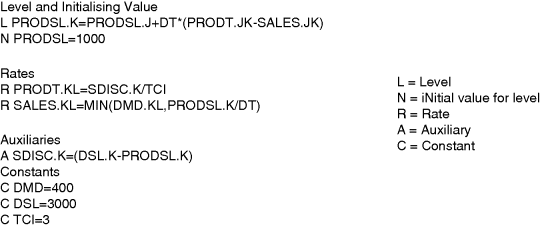
Figure 11.2 Example Cosmic code (Coyle, 1988).
In this simple example, the code required to develop a Cosmic model in 1987 is shown in Figure 11.2 and an equivalent model in Vensim is shown in Figure 11.3. Within the Cosmic software package each line of code would be hand-typed and, with the limit to parameter names set to six or eight characters, larger models required a glossary of acronyms in order for the reader to understand the model equations.

Figure 11.3 (a) Simple Vensim example. (b) Mapping to Cosmic parameter names from Figure 11.2.
If a second product were introduced into the example, the code would need to be manually copied and the parameter names for the additional product updated. For example, PRODSL would become PRODSL1 and PRODSL2 in order to represent two products. In modern software, the use of array structures would make this structure replication a trivial exercise.
In the late 1980s and early 1990s, new software packages such as Stella, Powersim and Vensim were making headway in the market. The new breed of SD software promised advances in productivity only ever dreamt of by users of early SD packages. Using graphical objects linked by arrows and pipes, developers were able to create models without resorting to handwritten code and having to remember the correct syntax. Basic syntax checking and automation enhanced capabilities further and, with the introduction of arrays, productivity improved by an order of magnitude. Simple equation editors became the norm enabling quick access to other model variables, units of measurement and hundreds of functions (Figure 11.4).

Figure 11.4 Vensim equation editor.
Some practitioners were initially sceptical, warning that the use of diagram-to-equation automation would jeopardise the learning experience and lead to fundamental errors in the formulation of models. It is true that early developers, because of the need to write out the level and rate formulations with explicit reference to time, time step and integration, could not avoid the need for a fundamental understanding of the underlying mathematics of the methodology. It is also true that developers today can ‘create’ simulation models that will run and produce results but will break all sensible rules, thus rendering the results meaningless.
In the beginning models were, although perhaps dynamically complex, structurally simple, out of necessity. Neither the software nor the hardware could handle anything more complex and so the models and modellers had to be innovative in order to address the issues of the day. Hardware platforms struggled to produce results quickly enough in order to respond to business needs and the turnaround of experimentation was time consuming and cumbersome; productivity was, by today's standard, ridiculously low. Some may argue, however, that having to be ‘elegant’ in the design of the model, having to really think of the most efficient way to formulate a model in sufficient detail to address the problem and yet still function within the software constraints of the day, enabled better models and better modellers.
11.4 The Move to User-Led Innovation
Enhancements to the SD software packages were heavily influenced by developments in the enabling tools, computing power and software development environments. Vendors' motivations to enhance the tools came from the software developers' insatiable need to innovate and, as their development tools (and they themselves) became more proficient, they applied their new-found skills to the improvement of the software. Those early improvements were software engineer led; optimisation algorithms, arrays and a plethora of under-the-hood enhancements enabled faster, more efficient simulation.
Enhancements were further influenced by the consultancy work undertaken by the vendors themselves, necessitating a tweak here and a tweak there in order to deliver to the customer's needs. Clients' influence on software development strengthened as vendors were able to respond to their specific requirements. For example, in the mid-1990s, end user insistence on documentation deliverables separately documenting stocks, flows, auxiliaries, and so on, led to a request from the modeller in question to the particular software vendor to add this functionality.
Unlike in many software development environments, the competitive imperative was not really a strong motivator for change. New features of one package may or may not show up in another but, if they did, it was invariably some considerable time later (in software timescales). In very recent years, social networking has enabled a much greater user involvement with vendor online forums enabling two-way communication between vendor and user. Conversation within, for example, the Ventana UK online forum (Ventana Systems UK, 2011) has led directly to enhancements or new features within the software. The ‘cottage-industry’ nature of the vendors also enhances the opportunities for direct, fruitful connection between vendor and user via e-mail, telephone and face-to-face opportunities during the annual SD conference and those organised by the many country chapters. Over the past 20 years, therefore, there has been a marked shift from vendor-led to user-led innovation.
Improvements in ease of use had another positive side-effect: they opened up the world of SD to more people. Gone was the requirement to be a computer programmer and so SD was able to make the move from the back-office computer lab to the executive desktop. The relative lack of success in making this transition has puzzled practitioners for decades; why is SD not the first tool in the business toolbox?
There have been many advances in SD software enabling enhanced efficiency for the modeller and, in turn, delivering more ‘bang for the buck’ for the end user. It can be argued, however, that the more important enhancements are those enabling SD to become what it was always intended to be: a means to increase understanding and, through learning, allow those with the luxury of being able to advise on or implement decisions to make better informed decisions. In order for decision makers to feel comfortable with SD in an advisory capacity, there exists a growing requirement to increase the ‘sex appeal’ of the software. Other tools and methods used to advise decision making have developed innovative ways to visualise and summarise data (such as Tableaux and Crystal Reports); the most commonly used ‘simulation’ or modelling package is Microsoft's Excel, itself vastly improved from the earliest versions, with enhanced graphics and connectivity to other Microsoft Office applications enabling ease of transfer between the most commonly used software tools on the planet. It is increasingly evident that there is a need to improve the ‘look and feel’ of the SD products and, more importantly, the ease by which output can be analysed, packaged and reported.
The next section will discuss software developments enabling enhanced support to the practitioner and end user (policy maker) in order to utilise efficiently the remarkable IT improvements made in recent years.
11.5 Software Support
Advances in IT hardware have enabled developers to increase the capabilities of the SD software and this has resulted in models becoming larger and more complex. As the SD software improves, its potential applications increase, leading to the potential for SD to contribute to decision making across a greater variety of problems. With this complexity and scope explosion, however, comes the need to avoid model development pitfalls introduced as a direct result of this complexity: that is, overly complex models resistant to the level of analysis required to support the understanding of the issues addressed by the modelling effort.
A number of features have been added to SD software to help mitigate the negative impact of increasingly complex models, even though the complexity itself is often introduced by the software improvements themselves! It is useful to discuss the software features within the context outlined by Sterman (2000) (see Figure 11.5), embedding the modelling effort within the dynamics of the system that the modelling effort is attempting to improve. In this way, the impact of improvements to the software can be assessed as they pertain to supporting the modelling effort but also to the successful application of the SD process in improving the system. Without the understanding and support of the policy makers, SD has no hope of contributing to system improvement in the real world; if SD is inaccessible, difficult to use or simply not capable enough, then it will not be used.
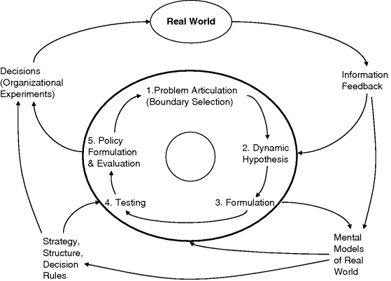
Figure 11.5 Modelling embedded in the dynamics of the system (Sterman, 2000).
The elicitation and understanding of the problem owners' ‘mental models of real world’ are central to the successful application of SD. These personally held hypotheses are derived from ‘information feedback’ received from direct and indirect observations of the ‘real world’. One important contribution to be made by the SD methodology is to provide a further signal enhancing, testing and validating these mental models, enabling multiple worldviews to be tested, rejected, negotiated and reformulated. The ‘modelling process’ should be as transparent as possible to the problem owners – after all, they are ultimately responsible for implementing policy decisions in the real world. In order to support these ‘organisational experiments’, policy makers need a significant degree of confidence in the modelling process and, with software/hardware improvements enabling increasingly complex representations of reality, a number of software developments have evolved out of necessity.
11.5.1 Apples and Oranges (Basic Model Testing)
In order for a model to be useful it must be credible. Credibility must be demonstrated and a number of features have evolved to support the practitioner in this regard. First of all, the practitioner needs to build confidence in the model he or she is creating. At the very least the model must pass a number of basic checks during ‘testing’, from syntax to mass balance checks and unit consistency.
Software features have been developed to automate or at least support testing, automatic units checking being a feature of Vensim from very early on in its history. There are many examples of incorrect or missing units as the main cause of poor model behaviour and units checking should be second nature to practitioners and a model with no or incomplete units should be regarded as suspect. Indeed, the Mars Climate Orbiter, launched by NASA on 11 December 1998, disintegrated as it mistakenly entered the Martian atmosphere. Investigations showed that this was as a direct result of units errors in ground-based software controlling the insertion of the probe into its correct orbit, with the loss of over $300 million.
11.5.2 Confidence
Confidence in the validity of the model is paramount to its successful use as a tool to inform decision making.
11.5.2.1 Calibration
One leg to the confidence table is the capability to reproduce past performance, that is to simulate a period of time over which there exists good data on the key stocks and flows in the system being modelled, whether the commodity price for an oil production model, sales history for a marketing model, production costs for a manufacturing model or the stock of vehicles in a country. If the model can be shown to replicate closely historical behaviour for the right reasons then the user will have greater confidence in the lessons learned from the simulator.
Calibration involves finding the values of model constants that make the model generate behaviour curves that best fit the real-world data. Manual calibration is a slow, painstaking process involving manipulation of the input assumptions, the running of the model, and the visual assessment of ‘goodness of fit’ for a range of performance indicators. Over the years, SD software tools have evolved in order to assist in this process, the most notable being the use of optimisation algorithms.
In the so-called ‘calibration optimisation’, the payoff is calculated as the accumulated differences between each historical and model-generated data point, the minimisation of which will result in a tendency to select model constant values minimising the difference between the historical data and the results generated by the model over the same historical period.
In the example in Figures 11.6 and 11.7 historical data exists for a number of key model variables, such as ‘vehicle penetration in region’. In the first instance, the software is informed of the variables for which historical data exists and, in the second, the range of values for which the selected assumptions may be searched in order to find a best fit.
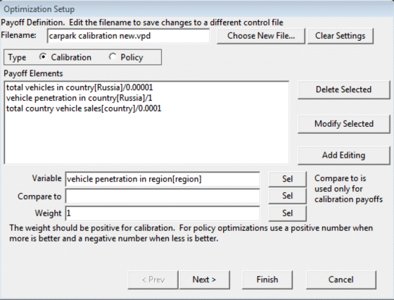
Figure 11.6 Vensim payoff definition for calibration.
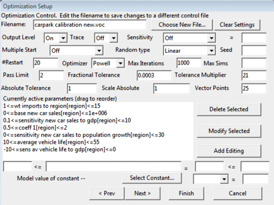
Figure 11.7 Vensim optimisation control for calibration.
Once a good fit has been achieved, the software provides a list of the constant values selected during calibration and these can be automatically used as input assumptions for future simulation runs. Figure 11.8 shows calibration output for the example model, where the calibration routine has found a good fit for vehicle penetration (in vehicles per thousand of population). Note that, in this case, some of the ‘historical’ data is actually ‘forecast’ data obtained from industry analysts.

Figure 11.8 Example calibration result.
11.5.2.2 Reality Checks
As models are built, there are various checks that must be done against reality. These checks may be explicit and take the form of tests of model behaviour or subsector behaviour under different assumptions, or they may be implicit mental simulations and analyses based on an understanding of models and the modelling process. In either case these checks are very important in ensuring that the models developed can adequately address the problems they are being applied to.
Reality checks provide a straightforward way to express statements that must be true about a model for it to be useful, and the machinery to test a model automatically for conformance with those statements. Reality Check is a technology that adds significantly to the ability to validate and defend models. It can also focus discussion away from specific assumptions made in models onto more solidly held beliefs about the nature of reality.
Models are representations of reality, or our perceptions of reality. In order to validate the usefulness of a model, it is important to determine whether things that are observed in reality also hold true in the model. This validation can be done using formal or informal methods to compare measurements and model behaviour. Comparison can be done by looking at time series data, seeing if conditions correspond to qualitative descriptions, testing sensitivity of assumptions in a model, and deriving reasonable explanations for model-generated behaviour and behaviour patterns.
Another important component in model validation is the detailed consideration of assumptions about structure. Agents should not require information that is not available to them to make decisions. There needs to be strict enforcement of causal connectedness. Material needs to be conserved.
Between the details of structure and the overwhelming richness of behaviour, there is a great deal that can be said about a model that is rarely acted upon. If you were to complete the sentence ‘For a model or submodel to be reasonable when I __ it should __’ you would see that there are many things that you could do to a model to find problems and build confidence in it.
In most cases, some of the things required for a model to be reasonable are so important that they get tested. In many cases, the things are said not about a complete model but about a small component of the model, or even an equation. In such cases the model builder can draw on experiences and the work of others relating to the behaviour of generic structures and specific formulations.
Ultimately, however, most of the things that need to be true for a model to be reasonable are never tested. Using traditional modelling techniques, the testing process requires cutting out sectors, driving them with different inputs, changing basic structure in selected locations, making lots of simulations, and reviewing the output. Even when this gets done, it is often done on a version of the model that is later revised, and the effect of the revisions not tested. Reality Check equations provide a language for specifying what is required for a model to be reasonable, and the machinery to go in and automatically test for conformance to those requirements. The specifications made are not tied to a version of a model. They are separate from the normal model equations and do not interfere with the normal function of the model. Pressing a button shows whether or not the model is in violation of the constraints that reality imposes.
The example in Figure 11.9 illustrates the use of reality checks in a policy model. There are two reality checks shown: ‘no demand, no production’ and ‘no demand, production capacity reduces to zero’. These are named in a fashion indicating the nature of the test inputs and the expected model behaviour. These equations are not part of the normal model structure and are not simulated during normal execution of the model. When a reality check experiment is called, however, each reality check is tested in turn, the software will force the test inputs to be true and it will compare model behaviour with the behaviour expected. For instance, in order to run these reality checks, the software forces ‘EU export sales’ and ‘EU domestic vehicle sales’ to be zero for the entire duration of the simulation run, and checks model behaviour, in this case ‘EU vehicle production capacity’ and ‘actual EU vehicle production’. If they conform to the expectation, the check is recorded as ‘passed’, while a ‘failure’ indicates a violation of this check.

Figure 11.9 Example reality check.
Such reality checks are developed by those with the greatest knowledge of the real-world system being explored. Failure of any of these checks would need to be investigated and any structural failures in the model rectified. Passing checks designed by the policy makers and/or subject matter experts is a powerful validation of any model.
11.5.2.3 Illuminating Model Behaviour
Communication between the model end user (decision maker) and model developer (practitioner) is of paramount importance in ensuring models are useful. As previously noted, the software and hardware available in the twenty-first century have enabled increasingly complex representations of systems to be modelled. Increasing model complexity requires increasingly sophisticated analytical tools and methods in order to maintain the necessary level of communication and, therefore, understanding of and confidence in the model. Without the ability to communicate model structure and behaviour, the practitioner is unable to validate the model in the eyes of the policy maker and the project is likely doomed to fail. All SD packages now use diagramming tools in the creation of the model and most support both CLD and stock–flow diagram (SFD) representations. Furthermore, Vensim includes the ability to create multiple ‘views’ of the model structure serving to emphasise one structural relationship or another, a particular feedback loop or part of an SFD. Combined with the use of symbols, colour, annotations and ‘story-telling’, the practitioner is able to engage more effectively with the problem owner; this leads to a greater understanding of the modelling process by the latter and of the mental model of the problem owner by the former.
As an example, a manufacturing model, developed as a research tool, is shown in Figure 11.10. Although the project team are able to navigate the model quickly and understand where key influences are likely to be the causes of particular model behaviour, it is clear that those without a similar SD background, or having not been involved in the project development, would need support in order to aid understanding. A first step may be to create another model ‘view’ and simplify the representation (the diagram in Figure 11.10 represents all equations and influences using an SFD approach) through simply adding a high-level pictorial representation, as shown in Figure 11.11.
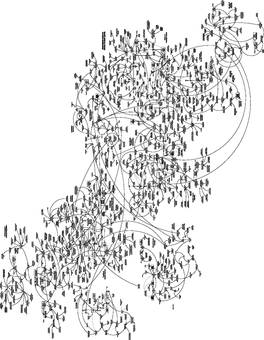
Figure 11.10 Manufacturing model.

Figure 11.11 Manufacturing model overview.
Here, the key influences only have been included and much of the intermediate calculation steps omitted for the sake of clarity. The diagram is still, unfortunately, overwhelming for many non-practitioners and so the user may choose to hide all but one small section of the model, the remainder to be progressively unveiled as the practitioner explains each stage of the diagram to the end user (story-telling). The use of font and colour changes further emphasises each section of the model and provides further visual support aiding understanding. In the recent past, this was achieved by copying the model and pasting multiple copies into, for example, Microsoft PowerPoint. Manipulation of each copy would enable story-telling as the reader progressed from slide to slide. This is now possible within many SD packages without the need to resort to copy and paste.
‘Story-telling’ is a powerful method for articulating the model structure as it relates to the behaviour of the system being modelled. Larger models tend to be made more readable through modularisation but decision makers often still have problems when faced with relatively simple modules, or ‘plates of spaghetti’. By allowing the practitioner to ‘hide’ model structure at multiple hide levels, model structure can be revealed in bite-sized, manageable portions. When coupled with explanatory notes appearing at each successive level, the practitioner is able to communicate more effectively with the end user.
Figures 11.12–11.16 show one such sequential ‘story-board’ where the practitioner is able to describe successfully a large proportion of the model with a series of building blocks beginning with a simple ‘call for maintenance’ to a maintenance service provider as a result of equipment failure at the manufacturer. In the next step (Figure 11.13), the impact of equipment failures at the manufacturer is explained as a reduction in plant productive time, further complicated by the availability or otherwise of spare parts to affect the repair.
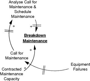
Figure 11.12 Story-telling 1.
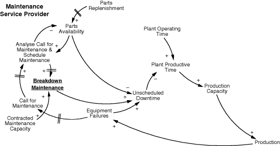
Figure 11.13 Story-telling 2.
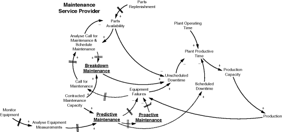
Figure 11.14 Story-telling 3.
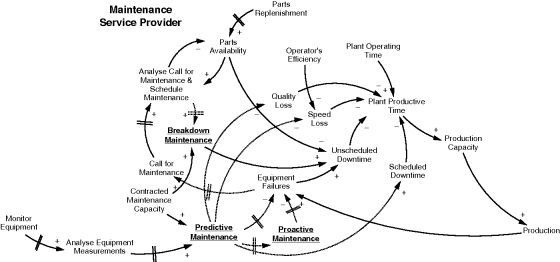
Figure 11.15 Story-telling 4.
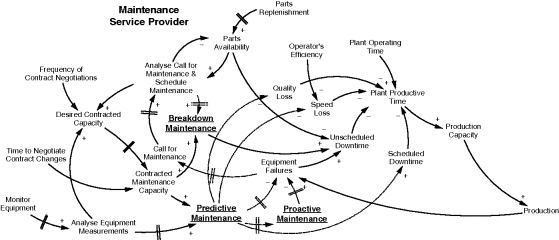
Figure 11.16 Story-telling 5.
Figure 11.14 introduces the concept of predictive and proactive maintenance. This requires the service provider to monitor the equipment for signs indicating potential failure in the future, and for those parts to be proactively replaced, thus reducing equipment failures and maintaining a higher plant productive time, even accounting for the scheduled downtime as a result of proactive maintenance, as such downtimes are predictable and can often be scheduled at times when the plant would not be operating anyway.
Other impacts on productivity are losses in production hours due to less than optimum operating as a result of worn parts. In Figure 11.15, the concepts of ‘speed loss’ and ‘quality loss’ are introduced in order to capture this effect on ‘plant productive time’.
Finally, Figure 11.16 includes the contracting issues as they affect the relationship between the manufacturer and its maintenance service provider. It is clear that insufficient contractual support may be the result of improper and infrequent contract reviews, especially if the manufacturing company is growing and, as a result, requesting greater contracted maintenance support.
Once a model is able to demonstrate it passes rudimentary tests, the syntax is correct, material is conserved, units are consistent, and so on, the practitioner will be able to start simulation testing in earnest. Observation of model-generated output and checking of the calculation made by each model equation form the next obvious steps in testing, and SD software analysis tools enable not only the verification that the model equations are calculating as intended, but that the output is valid under a range of assumptions. The ability to demonstrate why the model behaves in a particular way is a powerful means of gaining the confidence of the end user. As models increase in complexity, this ability to trace the cause-and-effect behaviour through layers of model structure becomes more difficult. Causal Tracing™ is a tool specifically designed to help the practitioner trace the causes of model behaviour, enabling a more rapid assessment of model output than would otherwise be possible. It is important to be able to interrogate the structure as well as the behaviour of the model, as the former determines the latter, while the latter should behave in a similar fashion to observed real-world behaviour and/or expected future behaviour.
In Figure 11.17, the simulated behaviour of ‘overall equipment effectiveness’ (OEE) is graphed and managers want to understand the reason for the observed cyclic behaviour. A causal tree for the output in question describes the immediate causal influences on this behaviour, ‘availability’, ‘performance’ and ‘quality’.
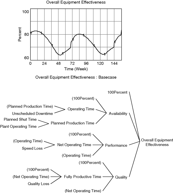
Figure 11.17 An example causal tree.
Immediately, the user can observe the direct structural influences on the output in question and follow this structural causality through multiple model layers. More powerfully, a causal ‘strip graph’ generates behavioural output for OEE (Figure 11.18, column ‘A’). It is immediately clear that the main influence on the OEE behavioural pattern is ‘availability’ and the user would naturally wish to pursue this avenue of investigation. By simply clicking on ‘availability’ in the displayed strip graph, a new strip graph is displayed showing graphical output for those immediate influences on ‘availability’ (column ‘B’).
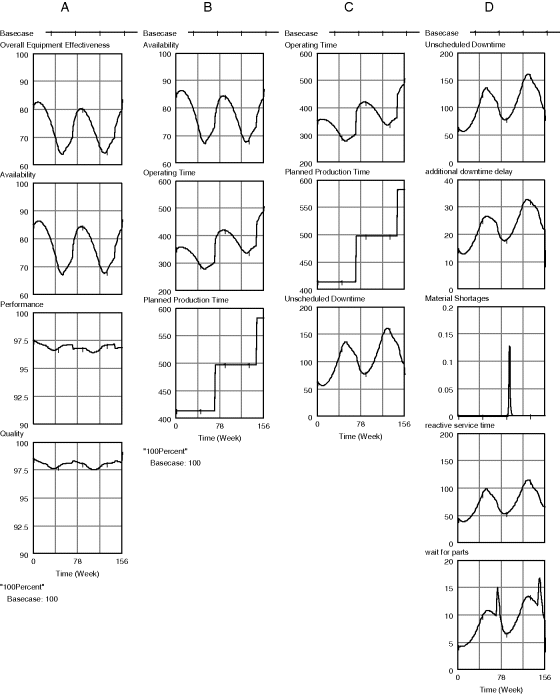
Figure 11.18 ‘Strip graphs’ help trace causes of behaviour.
Once again, the user is able to home in on the main cause of this behaviour and repeat the process (columns ‘C’ and ‘D’) and, in this particular case, track down the main cause of the oscillating OEE behaviour (in this complex model the causal tracing has to continue for some levels yet and, in this case, the oscillation was due to the feedback between usage of the manufacturing line and its rate of failure; the higher the number of failures, the less up-time leading to a change in the failure rate and greater up-time).
Causality can also be traced through tabular output of model values, assisting the developer in the verification process (Figure 11.19).

Figure 11.19 Causes Table.
11.5.3 Helping the Practitioner do More
One of the key improvements software vendors have made has been to enable the practitioner to achieve more in the limited time usually allotted to problem solving, especially in the business world. Practitioners need to elicit knowledge and experience from experts and capture this information in the form of CLDs and SFDs, formulate and create the model equations, evaluate and clean relevant data for use by the model and present this data in a readable and usable format, verify and validate the model, experiment within a wide range of scenarios, evaluate the sensitivity of the outputs to input uncertainty and communicate the results to the policy maker. Vendors have developed a suite of tools and methods to help the practitioner achieve many of these tasks as quickly and accurately as possible, enabling a reduction in total project cost or, perhaps more importantly, allowing more time to experiment alongside the policy maker and assist in the use of the model to understand the implication of policy options.
Assistance for the verification and validation of the model has been discussed, but there are other ways to improve not only the productivity of the practitioner, but also the communication of model content and output to the model user.
11.5.3.1 Model Documentation
Although seemingly of little importance to many model builders, a fully documented model is a must if it is to be peer reviewed and understood. Most of the software allows the model builder to enter textual descriptions for each equation and it is good practice to do so as the model is developed. Ventana has developed an advanced documentation add-on for Vensim, allowing model documentation to be created within Microsoft Excel. In Figure 11.22 below we see an example from the earlier example in this chapter. If the model builder has a written description of each variable in the ‘comments’ field of the equation editor, then this Excel documentation can be created with a few clicks of a mouse button.
Other tools can be added to Vensim by programmers with the necessary skills. For example, many end users would like to see more sophisticated documentation such as ‘data source’, ‘knowledge source’, ‘telecon information’, and so on, and a new application has been created to allow the model builder to enter documentation for a variable in the equation editor but under a range of user-defined fields.
For example, an application is created and set up to be activated upon a double click within the Vensim equation editor; this produces a ‘pop-up’ window, such as in Figure 11.20. The developer is then able to enter text under a series of user-defined fields.
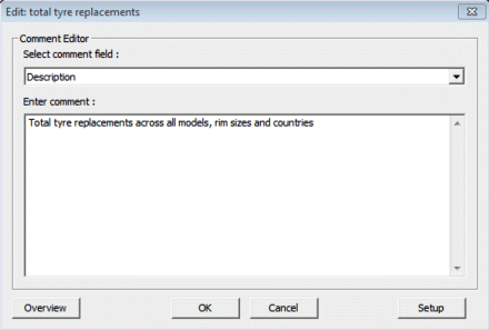
Figure 11.20 ‘Pop-up’ window for documentation.
Fields can be added, deleted and rearranged by the model developer (Figure 11.21) thus enabling a more sophisticated means of documenting each equation. In addition, the macro responsible for the Excel documentation in Figure 11.22 can be extended automatically to populate additional columns for each of the user-defined fields resulting in a fully documented list of variables indicating equation, type, group, causes, uses, units of measurement, subscript ranges, subscript elements and textual information under an unlimited number of user-defined headings.
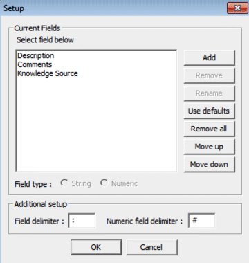
Figure 11.21 User configuration of the documentation tool.

Figure 11.22 Advanced documentation example using Excel macro.
11.5.3.2 Sensitivity Analysis
There are many occasions where uncertainty exists in the value of input assumptions for a model and one method of understanding the impact of this uncertainty is to vary the inputs and evaluate the impact on a number of key performance indicators (KPIs). In the past this would have involved time-consuming multiple experiments, although this has become automated in most software tools today, simply by listing the assumptions where uncertainty in the value exists and defining that uncertainty with the use of a random function from which to sample values. During sensitivity analysis, the software will repeat hundreds of simulations, each time sampling for the uncertain assumptions from their distributions, and the results stored as confidence bounds on the KPI outputs.
Figure 11.23 displays sensitivity output for ‘vehicle penetration in region’, a KPI from a vehicle ownership model trying to understand the possible future use of vehicles in an area of growing vehicle ownership. In this simple example, the developer wanted to assess the impact of uncertainty in a calibration estimate called ‘sensitivity new car sales to gdp’. This is added to the list of ‘currently active parameters’ (see Figure 11.24) and Vensim is instructed to select values from, in this case, a normal distribution function.
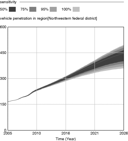
Figure 11.23 Example sensitivity output.
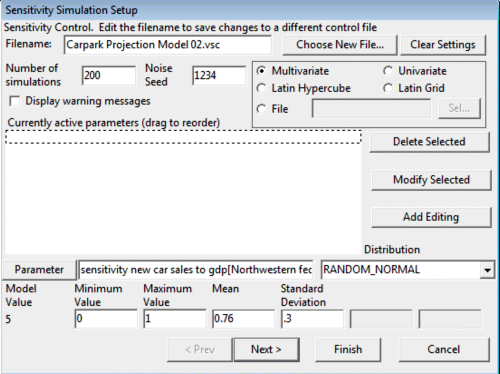
Figure 11.24 Sensitivity Simulation Setup.
11.5.3.3 Policy Optimisation
A powerful weapon in the SD software armoury is the use of optimisation. That is, the ability to instruct the software to use the model to maximise a desired outcome, usually profit. By setting a payoff definition file (in much the same way as in the calibration setup at 11.5.2.1) and instructing Vensim to select from a range of values for a number of policy levers, the software will attempt to find the best combination in order to achieve the optimisation, running many hundreds or even tens of thousands of simulations in the process.
In the business game example, users are asked to choose from a multitude of decisions each quarter, in gaming mode. That is, the user makes decisions and simulates the next quarter in order to evaluate the outcome of those decisions. The decisions are evaluated using a simple balanced scorecard; points are allotted for good performance under a range of KPIs and the cumulative points show the overall performance of the individual user. It is useful to compare the performance of each user but also useful to see how close they come to an optimal solution.
Using optimisation, each policy lever was allowed to be adjusted between its maximum and minimum values at each decision point (i.e. after each quarter). The optimisation algorithm found a best solution which can then be presented to the users as a yardstick by which to compare their performance (Figure 11.25).

Figure 11.25 Optimisation example.
Use of optimisation features presents the end user with something tangible: a means to understand the implications of policy change in the improvement of performance.
11.5.3.4 User Interface
If there is one innovation surely capable of enhancing the usability of SD models, it has been the ability to create user-friendly graphical user interfaces (GUIs). Many of the SD software packages allow interfaces to be developed in languages such as Visual Basic and C++ and some allow interaction with the model through Excel. The latter has the advantage of familiarity while all enable the developer to create an environment designed to maximise the use of the model with minimal effort from the user.
In the latter half of the 1990s, a move was made to develop a GUI tool for Vensim which would be better looking and easier to use than the in-built capability of the software at the time. This effort, initially developed by practitioners for specific clients, became the software now known as Sable. Sable enables professional interfaces to be developed in hours and days rather than weeks and presents to policy makers an easier interaction with the underlying model.
Sable is a drag-and-drop object-based application enabling rapid and easy access to model inputs and outputs together with the majority of Vensim in-built analysis tools such as Causal Tracing. The example in Figure 11.26 shows a screen from a simple interface created for a small simulation investigating the growth in energy micro-generation, that is the generation of electricity and heat at the point of use. The interface has two slider bars only (there are many other assumptions) and is designed as a quick introduction to SD for energy industry participants who are non-users of SD. The interface developer also created a story-telling screen to explain the model and the scenario the users are faced with, simply by linking to the relevant Vensim view in the underlying model (Figure 11.27).
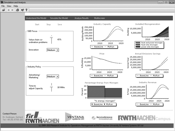
Figure 11.26 Example GUI in Sable.

Figure 11.27 Sable-enabled story-telling.
Interfaces have been created allowing multiple users simultaneous access to a single model on an organisation's intranet and enabling greater dissemination of the model and its results throughout the organisation. Forio (Forio Online Simulations, 2013) goes a step further by enabling Web-hosted interface applications compatible with many of the available SD software packages. Powersim and iThink are also examples of applications enabling interaction with models over the Internet, opening up SD use to the many.
11.6 The Future for SD Software
The future of SD is a topic often discussed and the debate nearly always seems to centre on ways to expand the use of SD in schools and colleges as a means of ‘seeding’ the business world and government with systems thinkers. Much effort is expended on this and many demonstrably successful examples are evident. However, we argue here that a critical reason for the disparity between potential and actual application of SD is in its lack of integration with the way in which business and government policy decisions are made. There seems to be too much emphasis on the fun bit, the building of the model, and not enough on the execution of the model in support of real decision making. This failure cannot always be laid at the door of the SD practitioners as it is often outside of their remit to become involved in the decision making or setting of policy, so it follows that the policy makers themselves must become the SD practitioners. Even though SD is ‘transparent’ and the methodology ‘simple’, SD tools today are only just becoming accessible in a format usable by everyone.
11.6.1 Innovation
In a plenary session at the 30th International System Dynamics Society (ISDS) Conference a panel was convened to discuss ‘Shaping the Future of System Dynamics: Challenges and Opportunities’ (System Dynamics Society, 2012). Although meeting with mixed reactions from the audience, Andreas Harbig and Craig Stephens (Greenwood Strategic Advisors, 2013) illustrated this frustration during their Socratic debate and identified the need for SD to become integrated with other analytical tools such as discrete-event simulation (DES), agent modelling, whatever it takes to become practically useful and innovative. The key term used was ‘innovation’ and it was argued that it will take a radical innovative move to enable SD to reach out as a feasible and widely used solution for business, government and other organisations.
Integrating other software applications with SD is not new. SD software has been ‘talking’ to Excel and databases for some time now and Vensim can exchange information with almost any other package with a little programming effort. Some of the software packages already handle mixed SD/DES/agent concepts and it is entirely possible to enable an SD simulation, from data entry, through simulation to evaluation of results, entirely within Excel. What may be needed, however, is an industrial-strength amalgam enabling a focus on the practical solutions that business and government policy makers can actually implement. With a focus on products and not just on building models, innovative solutions may then acquire the momentum to generate a huge upsurge of interest in SD.
11.6.2 Communication
Also at the same SD conference, it was suggested we should all ‘talk about’ SD wherever we are to whoever we are with. This may seem trivial and obvious and it is likely that system dynamicists do indeed talk about SD – with other system dynamicists! Maybe a small number of family or friends have listened patiently to an explanation of causality or feedback from an SD-wise partner while sharing a coffee at the breakfast table or watching the news. Reading a newspaper article or listening to a politician's speech can quickly lead to a red-faced, blood-boiling rant about poor journalism or research and incomprehensible political logic, but it is rare that such encounters lead to true knowledge transfer and so the pool of SD-savvy experienced individuals remains stagnant. Recently, however, there has been the development of viral gaming using the Facebook social network. Millions have tended farms, played poker, built (and destroyed) civilisations and generally interacted with each other through fun (and sometimes educational) games. And even more recently, system dynamicists are starting to exploit this medium as SD software vendors frantically race to enable their software on mobile platforms (iPad, smart phone, etc.) and innovative partnerships emerge between SD practitioners and gaming and graphics experts. One such example is typified by the Facebook game ‘Game Change Rio’, a collaboration between the developers of a sophisticated SD policy model, an expert gaming company and an SD software vendor (Biovision Foundation, CodeSustainable and Millennium Institute, 2013). The game allows users to make decisions in a host of policy areas affecting the environment, economics and well-being of all Earth's inhabitants. Behind the smart, brilliant interface is an actual SD model running and producing results as the outcome of the user decisions input via the Facebook interface (Figure 11.28).
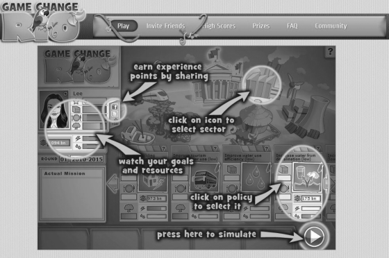
Figure 11.28 Game Change Rio Facebook game using SD.
Perhaps this is the way forward? What if actual real people started to think systemically? What if they started to understand the possibilities through interaction with insightful games playable from anywhere by anyone, games with an underlying engine designed by SD practitioners for real policy makers? What if, through interaction with such games, the popularity of a systems approach to policy making rises to encompass the majority? Business leaders and politicians would have to sit up and take notice wouldn't they?
References
- Banks, I.M. (2010) The State of the Art, Hachette, Littlehampton, p. 212.
- Biovision Foundation, CodeSustainable and Millennium Institute (2013) Game Change Rio. Available at https://www.facebook.com/gamechangerio (accessed 21 January 2013).
- Corel Corporation (2013) CorelDRAW Graphics Suite X6. Available at http://www.corel.com/corel/product/index.jsp?storeKey=gb&pid=prod4260069&trkid=UKSEMGGLGR&gclid=CNas_uqc-bQCFUbKtAodGwwA3Q#tab2&LID=40019623 (accessed 21 January 2013).
- Coyle, R.G. (1988) COSMIC User Manual, R G Coyle, Salisbury, pp. 1–20.
- Forio Online Simulations (2013) Contact. Available at http://forio.com/about-forio/contact-us/ (accessed 21 January 2013).
- Greenwood Strategic Advisors (2013) Contact. Available at http://www.greenwood-ag.com/contact.html (accessed 21 January 2013).
- IBM (2010) Capitalizing on Complexity: Insights from the Global Chief Executive Officer Study. Available at http://www-935.ibm.com/services/us/ceo/ceostudy2010/index.html (accessed 21 January 2013).
- NASA (1999) Mars Climate Orbiter Mishap Investigation Board Phase I Report. Available at http://sunnyday.mit.edu/accidents/MCO_report.pdf (accessed 21 January 2013).
- Sterman, J. (2000) Business Dynamics: Systems thinking and modeling for a complex world, McGraw-Hill, New York, pp. 83–104.
- System Dynamics Society (2012) Proceedings of the 30th International Conference of the System Dynamics Society, 22–26 July 2012, St Gallen, Switzerland. Available at http://www.systemdynamics.org/conferences/2012/index.html (accessed 21 January 2013).
- Ventana Systems UK (2011) Forum. Available at http://www.ventanasystems.co.uk/forum (accessed 21 January 2013).
