
Transmit Logic Functions
General
This section describes the various elements of the Physical Layer's transmit function (see Figure 26-11 on page 702). The transmit function consists of the following elements:
Data Buffer. Accepts the packet character stream from the Link Layer.
Multiplexer (Mux). Normally gates the packet data from the Data Buffer to the Byte Striping logic. Under some circumstances, however, the mux gates one of the following special patterns through to the Byte Striping logic:
- During link training, the mux gates TS1 or TS2 to the Byte Striping logic.
- At periodic intervals, the mux gates the special Skip Ordered Set pattern through to the Byte Striping logic to facilitate clock tolerance compensation in the receiver circuit of the port at the other end of the link.
- When there is no packet data to be transmitted, the mux gates the output of the Idle Sequence Generator through to the Byte Striping logic.
Byte-Striping Logic. When a port implements more than one data lane (i.e., more than one serial data path on the external link), the packet data is striped across the four or 12 data lanes by the Byte Striping logic.
8-bit to 10-bit Encoder(s). Encodes each 8-bit data or control character into a 10-bit character for transmission. When a port implements more than one data lane, there is one encoder per lane.
Serializer(s). Converts the encoded 10-bit character stream from the encoder into a serial bit-stream. When a port implements more than one data lane, there is one Serializer per lane.
Differential Transmit Driver(s). Transmits the serial bit stream onto the wire. When a port implements more than one data lane, there is one driver per lane.
Figure 26-11. Physical Layer Transmit and Receive Logic

The subsections that follow provide a description of each of these elements.
Transmit Data Buffer
The Data Buffer accepts packet data from the Link Layer one character at a time. The characters that comprise a packet are:
A start packet delimiter control character.
The body of the packet consisting of a stream of data characters.
An end of packet delimiter control character.
The characters are clocked to the Physical Layer's Data Buffer by the XmitClk supplied from the Link Layer.
When the Physical Layer's Data Buffer becomes full, it deasserts the XmitReady signal to the Link Layer. The Link Layer cannot stream additional packet characters to the Physical Layer until the XmitReady signal is reasserted.
Transmit Multiplexer (Mux)
The Transmit Mux can supply a character stream to the Byte Striping Logic from one of four possible sources:
Transmit Data Buffer. When the Link Layer is supplying a packet to be transmitted, the mux gates the packet's control and data character stream through to the Byte Striping Logic.
TS1/TS2 Generator. During link training, the mux gates the special TS1 and TS2 character sequences to the Byte Striping logic. A detailed description of link training can be found in “Link Training” on page 732.
Skip Ordered Set Generator. At periodic intervals, the mux gates the special Skip Ordered Set pattern through to the Byte Striping logic to facilitate clock tolerance compensation in the receiver circuit of the port at the other end of the link. For a detailed description, refer to “Inserting Clock Compensation Zones” on page 723.
Idle Sequence Generator. When there is no packet data to be transmitted, the mux gates the output of the Idle Sequence Generator through to the Byte Striping logic. For a detailed description of the Idle pattern, refer to “Idle Sequence Description” on page 722.
Byte Striping
When a port implements more than one data lane (i.e., more than one serial data path on the external link), the packet data is striped across the four or 12 data lanes by the Byte Striping logic. Byte Striping is illustrated in Figure 26-12 on page 704, Figure 26-13 on page 705, and Figure 26-14 on page 706.
Figure 26-12. 1X Byte-Striping

Figure 26-13. 4X Byte-Striping
Figure 26-14. 12X Byte-Striping

The number of lanes used is configured during the link training process (for a detailed description, refer to “Link Training” on page 732).
8-bit/10-bit Encoder per Lane
General
Each data lane implements an 8-bit to 10-bit Encoder that encodes each 8-bit data or control character into an equivalent 10-bit character. This encoding scheme has the following basic characteristics:
Invented by IBM in 1983. Also used in Gigabit Ethernet, Fibre Channel, ServerNet, FICON, and others.
The advantages of this encoding scheme are:
- Creates sufficient transition density (i.e., signal changes) to facilitate re-creation of the receive clock on the receiving end using a PLL (by guaranteeing a limited run length).
- Limited run length means that the encoding scheme ensures the signal line will not remain in a static high or low state for an extended period of time.
- 1s and 0s are clocked out on the rising edge of the transmit clock. At the receiver, a PLL can recreate the clock by sync'ing to the leading edges of 1s and 0s.
- Limited run length ensures minimum frequency drift in the receiver's PLL.
- Keeps the number of 1s and 0s transmitted as close to equal as possible, thus maintaining DC balance on the transmit line.
- Maintains a balance between the number of 1's and 0's on the signal line, thereby ensuring that the received signal changes state on a guaranteed, periodic basis. This is very important in capacitive- and transformer-coupled circuits. It maintains DC balance on the line.
- Permits encoding of special control characters.
- Facilitates the detection of most transmission errors.
Disadvantage: Due to the expansion of each 8-bit character into a 10-bit character prior to transmission, the actual amount of data transmitted is degraded by ~20% (everything has a price tag).
Properties of 10-bit Character
An equal number of 1's and 0's exists over two consecutive characters.
The bit stream never contains more than five continuous 1's or 0's (limited-run length)
In this encoding scheme, each 10-bit character contains:
- Four 0's and six 1's (not necessarily contiguous), or
- Six 0's and four 1's (not necessarily contiguous), or
- Five 0's and five 1's (not necessarily contiguous).
Each 10-bit character is subdivided into two sub-blocks: the first is six bits wide and the second is four bits wide.
- The 6-bit sub-block contains no more than four 1's or four 0's.
- The 4-bit sub-block contains no more than three 1's or three 0's.
Any character with other than the above properties is considered invalid.
The 8-bit character is submitted to the encoder along with a signal indicating whether this is a data (D) or control (K) character.
The currently defined control characters consists of COM, PAD, SKP, SDP, SLP, EGP, and EBP (detailed description later).
Preparing 8-bit Character for Encode
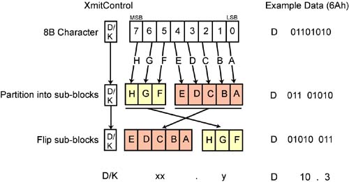
Refer to Figure 26-15 on this page with regard to the following:
The 8-bit character is submitted to the encoder with the data/control (D or K) indicator. In the illustration, the example character is the data character 6Ah.
The bits in the character are identified by the capitalized alpha designators A through H.
The character is partitioned in two sub-blocks: one 3-bits wide and the other 5-bits wide.
The two subblocks are flipped.
The character takes the written form zxx.y, where:
- z = D or K for Data or Control,
- xx = the decimal value of the 5-bit field,
- y = the decimal value of the 3-bit field.
The example character is represented as D10.3.
Figure 26-15. Preparing 8-bit Character for Encode
Disparity
Definition
The term disparity refers to the balance of 1s and 0s in a 10-bit character:
- When a character has more 0s than 1s, the character has negative (–) disparity (e.g., 0101000101b).
- When a character has more 1s than 0s, the character has positive (+) disparity (e.g., 1001101110b).
- When a character has an equal number of 1s and 0s, the character has neutral disparity (e.g., 0110100101b).
Each 10-bit character contains one of the following numbers of ones and zeros (not necessarily contiguous):
- Four 0's and six 1's (+ disparity).
- Six 0's and four 1's (– disparity).
- Five 0's and five 1's (neutral disparity).
Two Categories of 8-bit Characters
There are two categories of 8-bit characters:
- Those that encode into 10-bit characters with + or – disparity.
- Those that encode into 10-bit characters with neutral disparity
CRD (Current Running Disparity)
The CRD has the following characteristics:
- Its current state indicates the balance of 1s and 0s transmitted since link initialization.
- The CRD's initial state (before any characters are transmitted) can be + or –.
- The CRD's current state can be either positive (if more 1s than 0s have been transmitted) or negative (if more 0s than 1s).
- Each character is converted via a table lookup with the current state of the CRD factored in.
- As each new character is encoded, the CRD either remains the same (if the newly generated 10-bit character has neutral disparity) or it flips to the opposite polarity (if the newly generated character has + or – disparity).
Encoding Procedure
Refer to Figure 26-16 on page 711. The encode is accomplished by performing two table lookups in parallel (not shown separately in the illustration):
- Three elements are submitted to a 5-bit to 6-bit table for a lookup (see Table 26-10 on page 715 and Table 26-11 on page 716):
- The 5-bit portion of the 8-bit character (bits A through E).
- The Data/Control indicator.
- The current state of the CRD (positive or negative).
The table lookup yields the upper 6-bits of the 10-bit character (bits abcdei).
- Three elements are submitted to a 3-bit to 4-bit table for a lookup (see Table 26-12 on page 717 and Table 26-13 on page 717):
- The 3-bit portion of the 8-bit character (bits F through H).
- The Data/Control indicator.
- The current state of the CRD (positive or negative).
The table lookup yields the lower 4 bits of the 10-bit character (bits fghj).
Figure 26-16. 8-bit/10-bit Encoding

If the resultant 10-bit character is neutral (i.e., it has an equal number of 1s and 0s), the polarity of the CRD remains unchanged. If the resultant 10-bit character is + or –, the CRD flips to its opposite state. It is an error if the CRD is currently + or – and the next 10-bit character produced has the same polarity as the CRD.
Example Encodings
Figure 26-17 on page 712 illustrates some example 8-bit to 10-bit encodings. The following is an explanation of the first example (the conversion of the 8-bit data character 6Ah):
- The 8-bit character is broken down into its two sub-blocks: 011b and 01010b.
- The two sub-blocks are flipped and represented as the D10.3 character. The binary-weighted value of the 5-bit block is 10d and the value of the 3-bit field is 3d.
- The two blocks are submitted to their respective lookup tables (along with the Data/Control indicator and the current state of the CRD).
- The last two columns show the 10-bit character produced by the two parallel table lookups when the CRD is negative or positive, respectively.
Figure 26-17. Example 8-bit/10-bit Encodings

Example Transmission
Figure 26-18 on page 713 illustrates the encode and transmission of two characters: the first one is the control character BCh (K28.5) and the second is the data character 6Ah (D10.3).
- If the CRD is negative, the K28.5 is encoded into 001111 1010b (which has positive disparity). This flips the CRD from negative to positive.
- If the CRD is positive, the K28.5 is encoded into 110000 0101b (which has negative disparity). This flips the CRD from positive to negative.
- The D10.3 is encoded into either 010101 1100b or 010101 0011b, both of which have neutral disparity. The CRD therefore remains unchanged.
Figure 26-18. Example 8-bit/10-bit Transmission

Control Character Encoding
Figure 26-19 on page 714 illustrates the encoding of the currently defined control characters.
- Comma (COM) character. For more information, refer to “Character Boundary Sensing” on page 725.
- Pad character. For more information, refer to “12x Packet Format Rules” on page 721.
- Skip (SKP) character. For more information, refer to “Inserting Clock Compensation Zones” on page 723.
- Start Data Packet (SDP) delimiter. All data packets are preceded by this character.
- Start Link Packet (SLP) delimiter. All link packets (i.e., Flow Control Packets—FCPs) are preceded by this character.
- End Good Packet (EGP) delimiter. All good packets (both data packets and FCPs) end with this character.
- End Bad Packet (EBP) delimiter. For additional information, refer to “Packet Can Be Streamed through a Switch or Router” on page 657.
Figure 26-19. Control Characters

The Lookup Tables
The following tables define the table lookup for the two sub-blocks of 8-bit data and control characters.
| Data Byte Name | Unencoded Bits EDCBA | Current RD – abcdei | Current RD + abcdei |
|---|---|---|---|
| D0 | 00000 | 100111 | 011000 |
| D1 | 00001 | 011101 | 100010 |
| D2 | 00010 | 101101 | 010010 |
| D3 | 00011 | 110001 | 110001 |
| D4 | 00100 | 110101 | 001010 |
| D5 | 00101 | 101001 | 101001 |
| D6 | 00110 | 011001 | 011001 |
| D7 | 00111 | 111000 | 000111 |
| D8 | 01000 | 111001 | 000110 |
| D9 | 01001 | 100101 | 100101 |
| D10 | 01010 | 010101 | 010101 |
| D11 | 01011 | 110100 | 110100 |
| D12 | 01100 | 001101 | 001101 |
| D13 | 01101 | 101100 | 101100 |
| D14 | 01110 | 011100 | 011100 |
| D15 | 01111 | 010111 | 101000 |
| D16 | 10000 | 011011 | 100100 |
| D17 | 10001 | 100011 | 100011 |
| D18 | 10010 | 010011 | 010011 |
| D19 | 10011 | 110010 | 110010 |
| D20 | 10100 | 001011 | 001011 |
| D21 | 10101 | 101010 | 101010 |
| D22 | 10110 | 011010 | 011010 |
| D23 | 10111 | 111010 | 000101 |
| D24 | 11000 | 110011 | 001100 |
| D25 | 11001 | 100110 | 100110 |
| D26 | 11010 | 010110 | 010110 |
| D27 | 11011 | 110110 | 001001 |
| D28 | 11100 | 001110 | 001110 |
| D29 | 11101 | 101110 | 010001 |
| D30 | 11110 | 011110 | 100001 |
| D31 | 11111 | 101011 | 010100 |
| Data Byte Name | Unencoded Bits EDCBA | Current RD – abcdei | Current RD + abcdei |
|---|---|---|---|
| K28 | 11100 | 001111 | 110000 |
| K23 | 10111 | 111010 | 000101 |
| K27 | 11011 | 110110 | 001001 |
| K29 | 11101 | 101110 | 010001 |
| K30 | 11110 | 011110 | 100001 |
| Data Byte Name | Unencoded Bits HGF | Current RD - fghj | Current RD + fghj |
|---|---|---|---|
| --.0 | 000 | 1011 | 0100 |
| --.1 | 001 | 1001 | 1001 |
| --.2 | 010 | 0101 | 0101 |
| --.3 | 011 | 1100 | 0011 |
| --.4 | 100 | 1101 | 0010 |
| --.5 | 101 | 1010 | 1010 |
| --.6 | 110 | 0110 | 0110 |
| --.7 | 111 | 1110/0111 | 0001/1000 |
| Data Byte Name | Unencoded Bits HGF | Current RD – fghj | Current RD + fghj |
|---|---|---|---|
| --.0 | 000 | 1011 | 0100 |
| --.1 | 001 | 0110 | 1001 |
| --.2 | 010 | 1010 | 0101 |
| --.3 | 011 | 1100 | 0011 |
| --.4 | 100 | 1101 | 0010 |
| --.5 | 101 | 0101 | 1010 |
| --.6 | 110 | 1001 | 0110 |
| --.7 | 111 | 0111 | 1000 |
Differential Transmit Driver
The differential transmit driver transmits the serialized data differentially using NRZ encoding. There are 1, 4, or 12 transmit drivers (one per lane). Refer to Figure 26-4 on page 686 and Figure 26-11 on page 702.
Tx Clock
The serial output of each 8-bit/10-bit encoder is clocked out by the TxClock signal (see Figure 26-16 on page 711). Each 8-bit/10-bit encoder lane is clocked out to its respective differential driver using a transmit clock (Tx Clock). The clock frequency is 2.5GHz and it must be accurate to +/–100ppm. The clock can skew by one clock every 5000 clock cycles. Note that the TxClock is different from the XmitClock used by the Link Layer to clock the packet byte stream to the Physical Layer's Data Buffer.
Packet Format Rules
General Packet Format Rules
The following are the general packet format rules:
The total packet length (including delimiters) of each packet must be a multiple of four symbols.
Data packets always start with the SDP delimiter.
Link packets (FCPs; Flow Control Packets) always start with the SLP delimiter, are eight symbols long, and end with the EGP delimiter.
All data packets terminate with either an EGP or an EBP delimiter.
The startup state of the CRD is unspecified.
1x Packet Format
Figure 26-20 on page 719 illustrates the format of packets transmitted over a 1x link (i.e., a link with only one data lane operational). The illustration shows the following sequence of packets:
Two data packets.
One clock compensation packet consisting of a Skip Ordered Set (i.e., a COM followed by three SKP characters).
A data packet.
A Flow Control Packet.
Three data packets.
Idles transmitted because there are no packets to be transmitted.
Figure 26-20. 1x Packet Format

4x Packet Format Rules
The following rules apply when a packet is being transmitted over four data lanes (i.e., a 4x link):
SDP/SLP delimiters are always transmitted on lane 0.
EGP/EBP delimiters are always transmitted on lane 3.
When a SKIP ordered-set is transmitted (for clock compensation in the receiver), it must be sent on all four lanes simultaneously. See “Inserting Clock Compensation Zones” on page 723 for more information.
When an Idle data set is transmitted, it must be sent on all lanes. The pseudo-random data on each lane should start at a different point in the sequence. See “Idle Sequence Description” on page 722 for more information.
Figure 26-21 on this page illustrates the format of packets transmitted over a 4x link (i.e., a link with four data lanes operational). The illustration shows the following sequence of packets:
A data packet.
A Flow Control Packet.
A Skip Ordered Set being transmitted on all lanes for periodic receiver clock compensation.
A data packet.
Idles.
Figure 26-21. 4x Packet Format

12x Packet Format Rules
The following rules apply when a packet is being transmitted over 12 data lanes (i.e., a 12x link):
SDP/SLP delimiters are always transmitted on lane 0.
EGP/EBP delimiters are always transmitted on lane 3, 7, or 11.
If a packet doesn't end on lane 11, four or eight PAD symbols are added to keep the link aligned so the transmission of the next packet starts on lane 0.
When a SKIP ordered-set is transmitted (for receiver clock compensation), it must be sent on all 12 lanes. See “Inserting Clock Compensation Zones” on page 723 for more information.
When the Idle Ordered Set is transmitted, it must be sent on all lanes. The pseudo-random data on each lane should start at a different point in the sequence. See “Idle Sequence Description” on page 722 for more information.
Figure 26-22 on page 722 illustrates the format of packets transmitted over a 12x link (i.e., a link with 12 data lanes operational). The illustration shows the following sequence of packets:
A Flow Control Packet with PADs added.
A Skip Ordered Set being transmitted on all lanes for periodic receiver clock compensation.
A data packet with eight PADs added so the next packet will start on lane 0.
Idles.
Figure 26-22. 12x Packet Format

Mux Controls Idle, Skip, TS1, and TS2 Transmission
General
See Figure 26-11 on page 702. The Mux is controlled by the Training State Machine and Mux Control Logic. The TS1 and TS2 Ordered Sets are gated through to the Byte Striping Logic during link training. The Skip Ordered Set is gated through to the Byte Striping Logic periodically to insert clock tolerance compensation packets (see “Inserting Clock Compensation Zones” on page 723). The output of the Idle Generator is gated through to the Byte Striping Logic when there are no packets to transmit.
Idle Sequence Description
In order to keep the receiver's PLL sync'd up, something must be transmitted during periods when there is no packet data to transmit. The Idle sequence is transmitted. The Idle sequence is a pseudo-random sequence of data symbols generated by an 11th order LFSR (Linear Feedback Shift Register):
The LFSR consists of a shift register which, when clocked, advances a bit pattern derived from the exclusive-OR of two of its outputs (bits 9 and 11).
For a good explanation of an LFSR's operation, go to the Texas Instruments web site (www.ti.com) and perform a search for “LFSR.” One of the search results is a PDF document entitled “What Is an LFSR?”
When the link is idle (i.e., there are no packets or control Ordered Sets to transmit), a pseudo-random sequence of data symbols (idle data) is transmitted on all configured lanes.
Each lane may start the link idle pseudo-random data pattern at an arbitrary valid value. No lane-to-lane dependence is specified for the link idle pseudo-random data pattern.
In the final step of link configuration, the transmitter transmits the idle data stream on each configured lane and the receiver monitors the configured physical lanes waiting for a transition from TS2 Ordered Sets to Idle data. When Idle data is received, the link is up.
At a minimum, sixteen symbol times of link idle data are transmitted on each physical lane.
The IBA Idle data pattern has been selected to minimize EMI.
Inserting Clock Compensation Zones
Background
When the port receiver logic receives a character stream it sometimes needs to add or remove a symbol from the stream (for background, refer to “Receiver Clock Compensation Logic” on page 726). In addition, one or two repeaters may exist in between the two ports, and each repeater may sometimes add or delete a symbol—for more information, refer to “Repeater's Basic Operation” on page 755.
It should be obvious that the port's Physical Layer receive logic or a repeater can't arbitrarily pick a symbol to add or delete. This means that on a periodic basis, the transmit logic must transmit a special control character sequence that can be used for this purpose. This special control character sequence is referred to as the Skip Ordered Set (see Figure 26-23 on page 724). As transmitted by the originating port, the Skip set consists of a COM character followed by three SKP characters.
Figure 26-23. Skip Ordered Set
Skip Ordered Set Insertion Rules
A CA, router, or switch port's transmitter is required to transmit Skip Ordered Sets periodically:
The set must be scheduled for insertion at least once every 4608 symbol clocks (i.e., symbol times) and at most once every 4352 symbol clocks.
When it's time to insert a Skip set, it is inserted at the next packet or set boundary (not in the middle of a packet or set). Skips are inserted between packets simultaneously on all physical lanes.
In a multi-lane environment (4x or 12x link), the Skip Ordered Set must be transmitted on all lanes simultaneously (see Figure 26-13 on page 705 and Figure 26-14 on page 706). The link is padded as necessary to allow all of the Skip sets to start on the same clock.