
Receiver Logic Functions
Figure 26-24 on page 728 illustrates the receiver logic's front end. This is comprised of:
The differential receiver.
The clock recovery logic.
The COM character detector.
Lane-to-lane de-skew logic.
Deserializer.
Figure 26-24. Receiver Logic's Front End

Differential Receiver
Refer to Figure 26-4 on page 686. The differential receiver on each lane senses voltage differences > 175mV:
+ difference = logical 1.
– difference = logical 0.
A signal difference < 85mV is considered a signal absent condition. During this time, the receiver de-gates its input to prevent the error circuit from detecting an error.
When a device's Physical Layer is in the “sleep” state, it must at least be capable of detecting the beacon sequence (TS1).
Rx Clock
Using a PLL (Phase-Locked Loop), the receiver circuit generates the RxClock from the transitions in the input data stream. This recovered clock has the same frequency (2.5GHz) as the TxClock at the source port's transmitter. The RxClock is used to clock the 10-bit characters produced by the deserializer into the elastic buffer. The RxClock is different from the local clock that is used to clock data out of the elastic buffer. The local clock must be accurate to within +/–100ppm with respect to the RxClock.
Character Boundary Sensing
When the receive logic starts receiving a bit stream, it is JABOB (just a bunch of bits). The receive logic must have some way to determine the start of a 10-bit character. The Comma (COM) character serves this purpose.
The 10-bit encoding of the COM (K28.5) symbol contains 2-bits of one polarity followed by 5 bits of the opposite polarity (0011111010b or 1100000101b). Unless an error occurs, no other character has this property, thereby making it easily detectable. Upon detection of the COM character, the COM Detector knows that the next bit received after the COM character is the first bit of a valid 10-bit character.
The COM character is utilized under the following circumstances:
During link training when the link is first established, TS1 and TS2 Ordered sets are transmitted (and each set begins with a COM character). A detailed description of link training can be found in “Link Training” on page 732.
During link retraining initiated due to a problem on the link, TS1 (Figure 26-30 on page 739) and TS2 (Figure 26-32 on page 743) Ordered sets are transmitted (and each set begins with a COM character). See “Recovery State” on page 744 for a detailed discussion of link retraining.
Figure 26-30. TS1 Ordered Set (aka the beacon sequence)

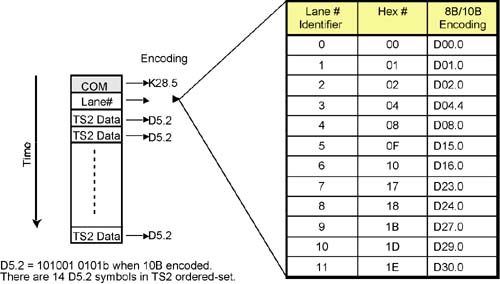
Figure 26-32. TS2 Ordered Set
Skip Ordered Sets (see Figure 26-23 on page 724) are sent periodically during normal operation to facilitate clock tolerance compensation in the receiver circuit (and each set begins with a COM character). A detailed description of clock tolerance compensation can be found in “Inserting Clock Compensation Zones” on page 723.
Deserializer
The incoming serial data on each lane is clocked into that lane's deserializer (the serial-to-parallel converter) by the Rx clock. The 10-bit characters produced are clocked into an elastic buffer.
Receiver Clock Compensation Logic
Background
The two CA, router, or switch ports at each end of a link each implement a transmitter and a receiver. The transmit clock accuracy must be 2.5GHz +/– 100 ppm (parts per million). Once the link is trained, the receive clock is the same as the transmit clock at the other end of the link (because the receive clock is derived from the bit stream that was transmitted at the remote end's transmit clock frequency). If the transmitter at one end of the link operates at +100 ppm and the transmitter at the opposite end operates at –100 ppm, this results in a worst-case 200 ppm difference between the two transmit clocks.
In this scenario, the transmitter at one end of the link is operating at 2.5GHz +100 ppm, while the receiver at the same end derives its receive clock from the remote port's transmitter frequency of 2.5GHz – 100ppm. The transmit and receive clocks in a port can therefore shift one clock (400ps) every 5000 clocks.
The Elastic Buffer's Role
It is a common design practice to clock most of the receive path logic using the Physical Layer's transmit clock. To compensate for the frequency difference between the transmit and receive clocks, an elastic buffer (see Figure 26-24 on page 728) is incorporated in the very early stages of the receive path.
Symbols arrive at the differential receiver as a bit stream and are presented to the deserializer. The deserializer recovers the clock embedded in the data and also converts the incoming bit stream into a series of 10-bit symbols. The symbols are clocked into the input side of the elastic buffer using the receive clock recovered from the incoming bit stream and are clocked out of the buffer using the local transmitter's transmit clock. As previously cited, these two clocks can be as much as 400ps out of sync with each other, so the point in time at which the transmit clock shifts a symbol out of the buffer can be misaligned by as much as 400ps.
The elastic buffer compensates for the difference between the transmit and receive clocks by either deleting a symbol from or inserting a symbol into the inbound symbol stream:
If the transmit clock frequency is greater than the receive clock frequency, a symbol is deleted from the buffer.
If the transmit clock frequency is less than the receive clock frequency, a symbol is added to the buffer.
It should be obvious that any characters deleted cannot be valid packet characters, and any characters added better not be recognized as valid packet characters. In other words, the transmitter on the other end must periodically transmit a special character sequence from which “don't care” characters can be deleted or to which “don't care” characters can be added. This special character sequence is the Skip Ordered Set (see Figure 26-23 on page 724). As transmitted by the originating port, the Skip Ordered Set consists of four control characters (a Comma and three Skips; the Skips are the “don't care” characters, hence the name “Skip”).
While in transit to the receiving port, the Skip Ordered Set may traverse up to two repeaters. Each of these repeaters incorporates an elastic buffer and may insert or delete a Skip character in the set (for information, see “Repeater's Basic Operation” on page 755). Upon Skip set receipt by the receiving port at the other end of the link, the Skip set will consist of a COM character followed by between one and five SKPs:
A COM plus three Skips if there are no in-line repeaters or if the repeater(s) did not add or delete Skips.
A COM plus five Skips if there are two in-line repeaters and if each of them inserted an additional Skip character.
A COM and two Skips if a repeater deleted one of the Skips from the set.
A COM and one Skip if there are two in-line repeaters and if each of them deleted a Skip character.
Loss of symbol(s) caused by elastic buffer overflow or underflow triggers link error recovery (see “Link Training” on page 732).
Major Error Detection
If a major error is detected in the receiver circuit, a message is sent to the Training State Machine to initiate Link Error Recovery. Additional information can be found in “Link Training” on page 732 and “Major Error Handling” on page 753.
10-bit/8-bit Decoder per Lane
Refer to Figure 26-25 on page 729. Each receiver lane incorporates a 10-bit/8-bit Decoder that decodes the 10-bit character stream into 8-bit data (D) or control (K) characters plus the RcvControl indicator. The received packet character stream is presented to the Link Layer one 8-bit character at a time. The state of RcvControl indicates to the Link Layer whether the RcvStream character is:
A data (D) character.
A control (K) character.
An idle (I) character.
An error (E) character. This indicates that the corresponding 10-bit character could not be decoded into a valid 8-bit data or control character.
Figure 26-25. 10-bit/8-bit Decoder per Lane

The decoder determines the initial disparity value based on the first character received.
Code Violation and Disparity Error Detection
General
This function detects errors in the received character stream. It should be noted that it doesn't catch all possible transmission errors. The two types of errors detected are:
Code violation errors (i.e., a 10-bit character could not be decoded into a valid 8-bit data or control character).
Disparity errors.
Errors are reported to the Link Layer via the RcvControl signal. There is no hardware error correction.
Code Violations
Any 6-bit sub-block containing more than four 1's or four 0's is in error.
Any 4-bit sub-block containing more than three 1's or three 0's is in error.
Any 10-bit character containing more than six 1's or six 0's is in error.
Any 10-bit character containing more than five consecutive 1's or five consecutive 0's is in error.
Any 10-bit character that doesn't decode into an 8-bit character is in error.
Disparity Errors
A character that encodes into a 10-bit character with disparity other than neutral is encoded into a 10-bit character with polarity opposite to that of CRD.
If the next character's disparity is the same as the CRD, a disparity error is detected.
Some disparity errors may not be detectable until the subsequent character is processed (see Figure 26-26 on this page).
Figure 26-26. Example of Delayed Disparity Error Detection

If two bits in a character flip, the error may not be detected (and the character may decode into a valid 8-bit character).
Byte Un-Striping
Figure 26-27 on this page illustrates the 12 decoded 8-bit character streams from the 12 decoders of a 12x link being un-striped into a single character stream which is fed to the filter logic (see the next section).
Figure 26-27. Example of 12x Byte Un-Striping

Filter and Packet Alignment Check
The 8-bit character stream produced by the Byte Un-Striping Logic is fed to the filter where Skip, TS1, and TS2 Ordered Sets, and PAD symbol are detected and filtered out before the character stream is placed in the receive Data Buffer in preparation for forwarding to the Link Layer.
All valid packets must start with a SDP or SLP delimiter and end with either an EGP or EBP delimiter. If a packet doesn't, an error is reported to the Link Layer on RcvControl.
Receive Data Buffer
The receive Data Buffer holds the received 8-bit data and control characters along with each character's RcvControl state. The buffer contents are clocked to the Link Layer using the RcvClk. The frequency of the RcvClk is not defined by the specification, but it must be able keep up with the received data stream speed.