
A computer game consists of many different pieces, all of which must come together to form a unique entertainment experience for the player. By far the most important piece of any game is the graphics. Graphics are used to represent the characters and creatures in a game, as well as background worlds and other interesting objects that factor into the overall game design. Granted, games have certainly done well because of factors outside of graphics, such as game play and sound quality, but those games are very rare. Besides, nowadays game players expect to see high-quality graphics just as we all expect to see high-quality visual effects in Hollywood movies. So, it’s important to develop a solid understanding of graphics programming and how to use graphics wisely in your games.
In this hour, you’ll learn:
The basics of drawing graphics using the Windows Graphics Device Interface
What a device context is, and why it’s important to GDI graphics
How to paint text and primitive graphics in Windows
How to create a sample program that demonstrates GDI graphics in the context of the game engine
Before jumping into the details of how graphics work in Windows and how they are applied to games, it’s important to establish some ground rules and gain an understanding of how computer graphics work in general. More specifically, you need to have a solid grasp on what a graphics coordinate system is, as well as how color is represented in computer graphics. The next couple of sections provide you with this knowledge, which you’ll put to practical use a little later in the hour.
All graphical computing systems use some sort of graphics coordinate system to specify how points are arranged in a window or on the screen. Graphics coordinate systems typically spell out the origin (0,0) of the system, as well as the axes and directions of increasing value for each of the axes. If you’re not a big math person, this simply means that a coordinate system describes how to pinpoint any location on the screen as an XY value. The traditional mathematical coordinate system familiar to most of us is shown in Figure 4.1.
Windows graphics relies on a similar coordinate system to specify how and where drawing operations take place. Because all drawing in Windows takes place within the confines of a window, the Windows coordinate system is applied relative to a particular window. The Windows coordinate system has an origin that is located in the upper-left corner of the window, with positive X values increasing to the right and positive Y values increasing down. All values in the Windows coordinate system are positive integers. Figure 4.2 shows how this coordinate system looks.
Figure 4.2. The Windows XY coordinate system is similar to the traditional coordinate system except that it applies to the client area of windows.
If the Windows graphics coordinate system sounds a little complicated, just think of it in terms of a classic game of Battleship. In Battleship, you try to sink enemy ships by firing torpedoes at specific locations on a grid. Battleship uses its own coordinate system to allow you to specify locations on the grid where ships might be located. Similarly, when you draw graphics in Windows you specify locations in the client area of a window, which is really just a grid of little squares called pixels.
A topic that impacts almost every area of game graphics is color. Fortunately, most computer systems take a similar approach to representing color. The main function of color in a computer system is to accurately reflect the physical nature of color within the confines of a computer. This physical nature isn’t hard to figure out; anyone who has experienced the joy of Play-Doh can tell you that colors react in different ways when they are combined with each other. Like Play-Doh, a computer color system needs to be able to mix colors with accurate, predictable results.
Color computer monitors provide possibly the most useful insight into how software systems implement color. A color monitor has three electron guns: red, green, and blue. The output from these three guns converges on each pixel on the screen, exciting phosphors to produce the appropriate color. The combined intensities of each gun determine the resulting pixel color. This convergence of different colors from the monitor guns is very similar to the convergence of different colored Play-Doh.
Note

Technically speaking, the result of combining colors on a monitor is different from that of combining similarly colored Play-Doh. The reason for this is that color combinations on a monitor are additive, meaning that mixed colors are added together to become white; Play-Doh color combinations are subtractive, meaning that mixed colors are subtracted from each other to become black. The additive or subtractive nature of a color combination is dependent on the physical properties of the particular medium involved.
The Windows color system is very similar to the physical system used by color monitors; it forms unique colors by using varying intensities of the colors red, green, and blue. Therefore, Windows colors are represented by the combination of the numeric intensities of the primary colors (red, green, and blue). This color system is known as RGB (Red Green Blue) and is standard across most graphical computer systems.
Table 4.1 shows the numeric values for the red, green, and blue components of some basic colors. Notice that the intensities of each color component range from 0 to 255
in value.
Table 4.1. Numeric RGB Color Component Values for Commonly Used Colors
Color | Red | Green | Blue |
|---|---|---|---|
White |
|
|
|
Black |
|
|
|
Light Gray |
|
|
|
Dark Gray |
|
|
|
Red |
|
|
|
Green |
|
|
|
Blue |
|
|
|
Yellow |
|
|
|
Purple |
|
|
|
The Win32 API defines a structure named COLORREF that combines the red, green, and blue components of an RGB color into a single value. The COLORREF structure is important because it is used throughout the Win32 API to represent RGB colors. To create a color as a COLORREF structure, you use the RGB() macro, which accepts red, green, and blue color components as arguments. Here is an example of creating a solid green color using RGB():
COLORREF green = RGB(0, 255, 0);
The color created in this line of code is green because the green component (the middle argument) is specified as 255, whereas the red and blue components are specified as 0. Changing the values of these three arguments alters the mix of the color—with lower numbers resulting in darker colors and higher numbers resulting in brighter colors.
In order to seamlessly support a wide range of graphical output devices, Windows handles the painting of graphics a little differently from you might expect. Instead of allowing you to draw directly to the screen, a layer called the Graphics Device Interface, or GDI, is used to separate drawing operations from physical graphics devices such as monitors and printers. You learned about the GDI to some extent in Hour 2, “A Windows Game Programming Primer,” but now it’s time to dig in and see how it actually works.
The role of the GDI is to provide a programmatic interface for painting graphics in a generic manner. GDI operations work in concert with Windows graphics drivers to communicate with physical graphics devices. Figure 4.3 shows the architecture of GDI.
Figure 4.3. The GDI in Windows provides a layer between graphics operations at the application (game) level and physical graphics devices.
Keep in mind that although I use the term “generic” to describe GDI graphics, the Win32 API provides a broad range of GDI graphics operations. In fact, the remainder of this hour is devoted to showing you some of the interesting things you can do with GDI graphics.
The key component in GDI graphics is the graphics context, or device context, which acts as a gateway to a physical graphics device. You can think of a device context as a generic drawing surface to which graphics are painted. In other words, a device context is like a piece of paper that you can draw on, except once you’ve drawn on it the resulting image can be displayed on a variety of different devices. Device contexts are very important in Windows programming because they make it possible to have device-independent graphics.
A device context is really just a way to allow you to draw in a generic manner, without worrying about where the drawing is physically taking place. Device contexts are necessary so that the same graphics routines can be used regardless of whether you are drawing to the screen, to memory, or to a printer. Granted, in game programming you’ll always be drawing to the screen, but that doesn’t mean you can just ignore the GDI. You have to go through a device context in order to draw graphics using the GDI, so you might as well get comfortable with them. The important thing to remember is that all the drawing you do in Windows is actually done to a device context. It is then up to Windows to make sure that the drawing on the device context gets properly displayed on the screen.
You normally obtain a device context by calling the Win32 BeginPaint()
function. If you recall from earlier hours, BeginPaint() is paired with EndPaint() to form a graphics drawing pair, like this:
PAINTSTRUCT ps;
HDC hDC = BeginPaint(hWindow, &ps);
*** GDI drawing operations go here ***
EndPaint(hWindow, &ps);
The BeginPaint() function
requires a window handle and a PAINTSTRUCT structure. The PAINTSTRUCT structure is filled with information pertaining to the device context, and is rarely used. The BeginPaint() function returns a handle to a device context, which is all you need to start drawing graphics using the GDI. The EndPaint() function is then responsible for releasing the device context once you’re finished with it.
It’s also possible to paint outside of the BeginPaint()/EndPaint() function pairing, in which case you have to obtain a device context in a slightly different manner. This is done using the GetDC() function, which only requires a window handle to obtain a device context. You must match the GetDC() function with the ReleaseDC()
function to release the device context when you’re finished using it. Following is an example of how these two functions are used together:
hDC = GetDC(hWindow);
*** GDI drawing operations go here ***
ReleaseDC(hWindow, hDC);
In addition to device contexts, the GDI also supports the following common graphics components that you’ll find useful in developing game graphics:
Pens
Brushes
Palettes
Bitmaps
The next few sections look at these graphics components in more detail, and help you to understand how they fit into the GDI, as well as game graphics.
Pens in the GDI are analogous to ink pens in the real world; they are used to draw lines and curves. Pens can be created with varying widths and in different colors. There are two kinds of pens: cosmetic and geometric. A cosmetic pen draws lines of fixed width and lines that need to be drawn quickly. A geometric pen draws scaleable lines, lines that are wider than a single pixel, and lines with unique styles. Given that cosmetic pens offer the speediest approach to drawing, they are the pen type most commonly used in game programming.
Brushes in GDI are analogous to paint brushes in the real world; they are used to paint the interior of polygons, ellipses, and paths. Although you might commonly think of a paint brush as using a solid color, GDI brushes can also be defined based on a bitmap pattern, which means that they paint in a pattern instead of as a solid. Brushes and pens go hand in hand when drawing graphics using the GDI. For example, if you were to draw a circle, a pen would be used to draw the outline of the circle, whereas a brush would be used to paint its interior.
A bitmap is a graphical image stored as an array of pixels. If you’ve ever used a digital camera or seen pictures on a Web site, you are already familiar with bitmaps. Bitmaps are rectangular, so the number of pixels in a bitmap is the width of the bitmap multiplied by its height. Bitmaps can contain multiple colors and are often based on a specific palette, or set of colors. Bitmaps are, without a doubt, the most important graphics component in game programming because they provide the most flexibility in terms of using high-quality artwork. Unfortunately, bitmaps are a little more complex to use at the programming level, which is why you don’t go into details with them until the next hour.
A palette is a set of colors used by the GDI when rendering a bitmap. As an example, many images (bitmaps) are stored as 256-color images, which means that they use colors from a palette of 256 colors. Depending on the specific settings of your screen in Windows, the GDI might have to map the color palette for a bitmap to the color palette used by the screen. Most of the complexities of palette management are handled automatically by Windows. However, you do have to concern yourself somewhat with the palette used by bitmaps. Hour 5, “Drawing Graphical Images,” shows you how to work with palettes as they relate to bitmaps.
As you might remember
from previous hours, the Win32 API includes a special message that is delivered to a Window whenever it needs to be painted. This message is called WM_PAINT,
and it serves as one of the main ways in which graphics are drawn to a window. A window might need to be repainted when the window is first created, when the window is uncovered from behind other windows, or a variety of other reasons. The bottom line is that you must handle the WM_PAINT message in order to paint the inside (client area) of a window.
When I refer to painting or drawing to a window, I’m really referring to the client area of a window. This is the rectangular part of a window inside the window’s border that doesn’t include the window frame, caption, menu, system menu, or scrollbars. Figure 4.4 reveals how the coordinates of the client area begin in the upper-left corner of the window and increase down and to the right, as you learned earlier in the hour. This coordinate system is very important because most GDI graphics operations are based on them.
Figure 4.4. Most graphics in a Windows program are drawn to the client area of a window, which uses the Windows graphics coordinate system.
As you might recall, the handling of messages takes place in the WndProc()
function for a window. However, we were smart enough to make things simpler with the game engine you created in the previous hour. More specifically, a WndProc() function is hidden in the game engine that handles the WM_PAINT message and calls the GamePaint()
function. However, the call to the GamePaint() function is sandwiched between calls to the Win32 BeginPaint()
and EndPaint() functions. This allows you to place graphics code in the GamePaint() function of your game without having to worry about obtaining a device context. Following is the WM_PAINT message handler in the WndProc() function, which shows how the GamePaint() function is called:
case WM_PAINT:
  HDC         hDC;
  PAINTSTRUCT ps;
  hDC = BeginPaint(hWindow, &ps);

  // Paint the game
  GamePaint(hDC);

  EndPaint(hWindow, &ps);
  return 0;
The device context obtained from BeginPaint()
is passed into the GamePaint() function to delegate the specifics of drawing graphics to each individual game. Following is an example of a simple GamePaint() function:
void GamePaint(HDC hDC)
{
  *** GDI drawing operations go here ***
}
GDI painting operations are performed on a device context, or DC, which is passed into the function via the hDC argument. Following is an example of drawing a line in the
GamePaint() function:
void GamePaint(HDC hDC)
{
  MoveToEx(hDC, 0, 0, NULL);
  LineTo(hDC, 50, 50);
}
This code shows how to draw a line using GDI functions. You learn more about how these functions work in a moment, but first let’s take a look at how to draw text.
In Windows, text is treated
no differently from graphics, which means that text is painted using GDI functions. The primary GDI function used to paint text
is TextOut(), which looks like this:
BOOL TextOut(HDC hDC, int x, int y, LPCTSTR szString, int iLength);
Following are the meanings
of the different arguments to the TextOut() function:
hDC—. Device context handlex—. X coordinate of text positiony—. Y coordinate of text positionszString—. The string to be paintediLength—. Length of the string to be painted
The first argument to TextOut() is a handle to a device context, which is provided by the BeginPaint()
function. All GDI functions require a handle to a device context, so you should get comfortable with seeing it in graphics code. The x and y arguments specify the position of the upper-left corner of the first string character relative to the client area (Figure 4.5), whereas the last two arguments are a pointer to a string and the length of the string, in characters.
Figure 4.5. Text is drawn at the upper-left corner of the first character with respect to the client area of a window.
Following is an example
of how to use the TextOut() function to draw a simple string of text:
void GamePaint(HDC hDC)
{
  TextOut(hDC, 10, 10, TEXT("Michael Morrison"), 16);
}
Another text-related function that you might consider using is DrawText(),
which allows you to draw text within a rectangle, as opposed to drawing it at a specified point. As an example, you can use DrawText() to center a line of text on the screen by specifying the entire client window as the rectangle in which to draw the text. Following is an example of using the DrawText() function in place of TextOut():
void GamePaint(HDC hDC)
{
  RECT rect;
  GetClientRect(hWindow, &rect);
  DrawText(hDC, TEXT("Michael Morrison"), -1, &rect,
    DT_SINGLELINE | DT_CENTER | DT_VCENTER);
}
In this example, the text is drawn centered both horizontally and vertically in the entire client area of the window. Notice that the length of the text string isn’t necessary; this is because -1 is provided as the length, which means that the length should be automatically determined because the string is null-terminated. The flags in the last argument of DrawText() are used to determine how the text is drawn, which in this case causes the text to be centered both horizontally and vertically.
Graphics primitives form a fundamental part of GDI, and consist of lines, rectangles, circles, polygons, ovals, and arcs. You can create pretty impressive graphics by using these primitives in conjunction with each other. Following are the major graphics primitives you can paint with GDI functions:
Lines
Rectangles
Ellipses
Polygons
The next few sections demonstrate how to draw each of these graphics primitives, along with how to use pens and brushes to add color to them.
Lines are the simplest
of the graphics primitives and are therefore the easiest to draw. Lines are painted using the MoveToEx()
and LineTo() functions, which set the current position and draw a line connecting the current position to a specified end point, respectively. The idea is that you use MoveToEx() to mark the position of a point, and then use LineTo() to draw a line from that point to another point. You can continue to draw lines connecting points by calling LineTo() again. Following are what these functions look like:
BOOL MoveToEx(HDC hDC, int x, int y, LPPOINT pt);
BOOL LineTo(HDC hDC, int x, int y);
Note
An XY coordinate in Windows is referred to as a point, and is often represented by the Win32 POINT structure. The POINT structure is used throughout Windows to represent coordinates for a variety of different operations. The POINT structure consists solely of two long integer fields, x and y.
Both functions accept a handle to a device context and an X and Y value for the point of the line. The MoveToEx() function also allows you to provide an argument to store the previous point. In other words, you can pass a pointer to a point as the last argument of MoveToEx() if you’re interested in finding out the last point used for drawing. Following is an example of using MoveToEx() and LineTo() to draw a couple of lines:
void GamePaint(HDC hDC)
{
  MoveToEx(hDC, 10, 40, NULL);
  LineTo(hDC, 44, 10);
  LineTo(hDC, 78, 40);
}
In this code, the drawing position is first set by calling MoveToEx() and providing the XY position of a point. Notice that the final argument is passed as NULL, which indicates that you aren’t interested in finding out the previous point. The LineTo() function is then called twice, which results in two connected lines being drawn.
Rectangles represent
another type of graphics primitive that are very easy to draw. The Rectangle()
function enables you to draw a rectangle by specifying the upper-left corner and the lower-right corner of the rectangle. Following is the prototype for the Rectangle() function, which helps to reveal its usage:
BOOL Rectangle(HDC hDC, int xLeft, int yTop, int xRight, int yBottom);
The Rectangle() function is straightforward in that you pass it rectangular dimensions of the bounding rectangle for the rectangle to be painted. Following is an example of how to draw a couple of rectangles:
void GamePaint(HDC hDC)
{
  Rectangle(hDC, 16, 36, 72, 70);
  Rectangle(hDC, 34, 50, 54, 70);
}
There isn’t really anything remarkable about this code; it simply draws two rectangles of differing sizes and positions. Don’t forget that the last two arguments to the Rectangle() function are the X and Y positions of the lower-right corner of the rectangle, not the width and height of the rectangle.
Although they
are curved, ellipses are drawn in a manner very similar to rectangles. An ellipse is simply a closed curve, and therefore can be specified by a bounding rectangle. The circular explosions in the classic Missile Command game are a very good example of a filled ellipse. Ellipses are painted using the Ellipse() function, which looks like this:
BOOL Ellipse(HDC hDC, int xLeft, int yTop, int xRight, int yBottom);
The Ellipse() function accepts the rectangular dimensions of the bounding rectangle for the ellipse to be painted. Following is an example of drawing an ellipse using the Ellipse() function:
void GamePaint(HDC hDC)
{
  Ellipse(hDC, 40, 55, 48, 65);
}
Not surprisingly, this code draws an ellipse based on four values that specify a bounding rectangle for the ellipse.
The trickiest of graphics
primitives is the polygon, which is a closed shape consisting of multiple line segments. The asteroid shapes in the popular Asteroids game are a great example of polygons. Polygons are painted using the Polygon()
function, which follows:
BOOL Polygon(HDC hDC, CONST POINT* pt, int iCount);
As you can see, the Polygon() function is a little more complex than the other graphics primitives functions in that it takes an array of points and the number of points as arguments. A polygon is painted by connecting each of the points in the array with lines. Following is an example of how to draw a polygon shape using the Polygon() function:
void GamePaint(HDC hDC)
{
  POINT points[3];
  points[0] = { 5, 10 };
  points[1] = { 25, 30 };
  points[2] = { 15, 20 };
  Polygon(hDC, points, 3);
}
The key to this code is the creation of the array of points, points, which contains three POINT structures. These three POINT structures are initialized with XY pairs, and the whole array is then passed into the Polygon() function, along with the total number of points in the array. That’s all that is required to draw a polygon shape consisting of multiple line segments.
It’s one thing to simply draw graphics primitives in their default mundane black and white style. It’s quite another to control the line and fill colors of the primitives to get more interesting results. This is accomplished by using pens and brushes, which are standard GDI objects used in drawing graphics primitives. Whether you realize it or not, you’re already using pens and brushes when you draw graphics primitives. It’s just that the default pen is black, and the default brush is the same color as the window background.
If you want to change
the outline of a graphics primitive, you need to change the pen used to draw it. This typically involves creating a new pen, which is accomplished with the
CreatePen() function:
HPEN CreatePen(int iPenStyle, int iWidth, COLORREF crColor);
The first argument is the style of the pen, which can be one of the following values: PS_SOLID, PS_DASH, PS_DOT, PS_DASHDOT, PS_DASHDOTDOT, or PS_NULL. All but the last value specify different kinds of lines drawn with the pen, such as solid, dashed, dotted, or a combination of dashed and dotted. The last value, PS_NULL, indicates that no outline is to be drawn; in other words, the pen doesn’t draw. The second argument to CreatePen() is the width of the pen, in logical units, which typically correspond to pixels when drawing to the screen. The final argument is the color of the pen, which is specified as a COLORREF value. To help make things clear, following is an example of how to create a solid blue pen that is one-pixel wide:
HPEN hBluePen = CreatePen(PS_SOLID, 1, RGB(0, 0, 255));
Keep in mind that simply creating a pen isn’t enough to begin drawing with it. In a moment you learn how to select a pen into a device context and begin drawing with it. However, let’s first learn how to create brushes.
Although several different
kinds of brushes are supported in the GDI, I’d like to focus on solid brushes, which allow you to fill in graphics shapes with a solid color. You create a solid brush using the Win32 CreateSolidBrush()
function, which simply accepts a COLORREF structure. Following is an example of creating a purple brush:
HBRUSH hPurpleBrush = CreateSolidBrush(RGB(255, 0, 255));
Notice in this code that a value of 255 is used to set the red and blue components of the color, which is how you are achieving purple in the final mixed color. Now that you have a handle to a brush, you’re ready to select it into a device context and begin painting with it.
In order to use a pen
or brush you’ve created, you must select it into a device context using the Win32 SelectObject()
function. This function is used to select graphics objects into a device context, and applies to both pens and brushes. Following is an example of selecting a pen into a device context:
HPEN hPen = SelectObject(hDC, hBluePen);
In this example, the hBluePen you just created is selected into the device context. Also notice that the previously selected pen is returned from SelectObject() and stored in hPen. This is important because you will typically want to restore GDI settings to their original state when you’re finished painting. In other words, you want to remember the original pen so that you can set it back when you’re finished. Following is an example of restoring the original pen using SelectObject():
SelectObject(hDC, hPen);
Notice that it is no longer important to remember the return value of SelectObject() because you are restoring the original pen.
One more important task related to creating pens is that of deleting graphics objects that you create. This is accomplished with the DeleteObject()
function, which applies to both pens and brushes. It is important to delete any graphics objects that you create after you’ve stopped using them and they are no longer selected into a device context. Following is an example of cleaning up the blue pen:
DeleteObject(hBluePen);
Selecting and deleting brushes is very similar to selecting and deleting pens. Following is a more complete example to illustrate:
HBRUSH hBrush = SelectObject(hDC, hPurpleBrush);
// *** Do some drawing here! ***
SelectObject(hDC, hBrush);
DeleteObject(hPurpleBrush);
In this example, the purple brush from the previous section is selected into the device context, some drawing is performed, and the old brush is restored. The purple brush is then deleted to clean up everything.
At this point, you’ve seen bits and pieces of GDI graphics code, and you’ve learned how to carry out basic drawing operations with a variety of different graphics shapes. You’ve also learned how to tweak the appearance of those shapes by creating and using different pens and brushes. You’re now ready to put what you’ve learned into a complete example program that demonstrates how to draw graphics in the context of a game. Okay, you’re not really creating a game in this hour, but you are using the game engine to draw some pretty neat graphics. The example program I’m referring to is called Trippy, and its name comes from the fact that it displays a psychedelic series of rectangles in different sizes and colors.
The idea behind the Trippy program
is to draw a random rectangle in each cycle of the game engine. Although the rectangles are drawn outside of the GamePaint()
function in response to a game cycle, it is still important to demonstrate how to draw within GamePaint() so that the drawing isn’t lost when the window is minimized or hidden. For this reason, Trippy draws a grid of lines in GamePaint() to demonstrate how graphics drawn in this function are retained even if the window must be repainted. The actual rectangles are drawn in GameCycle(),
which means that they are lost if the window is repainted. Let’s take a look at how the code actually works for this example program.
The fun begins in the Trippy program example with the header file, Trippy.h, which is shown in Listing 4.1. All of the code for the Trippy program is available on the accompanying CD-ROM.
Example 4.1. The Trippy.h Header File Imports a Few Header Files and Declares the Global Game Engine Pointer, as Well as the Previous Rectangle That Was Drawn
 1: #pragma once
 2:
 3: //-----------------------------------------------------------------
 4: // Include Files
 5: //-----------------------------------------------------------------
 6: #include <windows.h>
 7: #include "Resource.h"
 8: #include "GameEngine.h"
 9:
10: //-----------------------------------------------------------------
11: // Global Variables
12: //-----------------------------------------------------------------
13: GameEngine* _pGame;
14: RECT        _rcRectangle;
This code isn’t too mysterious. In fact, the only real difference between this header and the one you saw for the Game Engine example in the previous hour is the declaration of the _rcRectangle global variable (line 14). This rectangle stores the previously drawn rectangle, which allows you to alter its position randomly for the next rectangle. The end result is that the rectangles tend to randomly drift around the screen, as opposed to popping up in random locations all over the place.
Moving right along, remember that we’re now taking advantage of the game engine to simplify a great deal of the work in putting together programs. In fact, all that is really required of the Trippy program is to provide implementations of the core game functions. Listing 4.2 contains the code for the first of these functions, GameInitialize().
Example 4.2. The GameInitialize()
Function Creates the Game Engine and Sets the Frame Rate to 15 Cycles Per Second
 1: BOOL GameInitialize(HINSTANCE hInstance)
 2: {
 3:   // Create the game engine
 4:   _pGame = new GameEngine(hInstance, TEXT("Trippy"),
 5:     TEXT("Trippy"), IDI_TRIPPY, IDI_TRIPPY_SM);
 6:   if (_pGame == NULL)
 7:     return FALSE;
 8:
 9:   // Set the frame rate
10:   _pGame->SetFrameRate(15);
11:
12:   return TRUE;
13: }
The GameInitialize() function is responsible for creating the game engine (lines 4 and 5) and setting the frame rate for it (line 10). In this case, the frame rate is set at 15 cycles per second (frames per second), which is plenty to demonstrate the psychedelic nature of the rectangles.
Following up on GameInitialize() is GameStart(),
which actually gets things going. Listing 4.3 shows the code for the GamStart() function.
Example 4.3. The GameStart() Function
Seeds the Random Number Generator and Establishes an Initial Rectangle
 1: void GameStart(HWND hWindow)
 2: {
 3:   // Seed the random number generator
 4:   srand(GetTickCount());
 5:
 6:   // Set the position and size of the initial rectangle
 7:   _rcRectangle.left = _pGame->GetWidth() * 2 / 5;
 8:   _rcRectangle.top = _pGame->GetHeight() * 2 / 5;
 9:   _rcRectangle.right = _rcRectangle.left + _pGame->GetWidth() / 5;
10:   _rcRectangle.bottom = _rcRectangle.top + _pGame->GetHeight() / 5;
11: }
Any program that makes use
of random numbers is responsible for seeding the built-in random number generator. This is accomplished in line 4 with the call to srand(). You’ll see this line of code in virtually all the program examples throughout the book because most of them involve the use of random numbers; random numbers often play heavily into the development of games. The remainder of the GameStart() function is responsible for setting the position and size of the initial rectangle to be drawn (lines 7–10). This rectangle is sized proportionally to the client area of the main program window, and positioned centered within the client area.
I mentioned earlier that part of the Trippy program was to demonstrate the difference between drawing graphics in the GamePaint() function, as opposed to drawing them in GameCycle(). Listing 4.4 shows the code for GamePaint(), which in this case is responsible for drawing a bunch of grid lines as a background for the rectangles.
Example 4.4. The GamePaint()
Function Draws a Grid of Lines to Fill the Entire Client Area
 1: void GamePaint(HDC hDC)
 2: {
 3:   // Draw grid lines as a background for the rectangles
 4:   const int iGridLines = 50;
 5:   for (int i = 1; i <= iGridLines; i++)
 6:   {
 7:     // Draw a horizontal grid line
 8:     MoveToEx(hDC, _pGame->GetWidth() * i / iGridLines, 0, NULL);
 9:     LineTo(hDC, _pGame->GetWidth() * i / iGridLines, _pGame->GetHeight());
10:
11:     // Draw a vertical grid line
12:     MoveToEx(hDC, 0, _pGame->GetHeight() * i / iGridLines, NULL);
13:     LineTo(hDC, _pGame->GetWidth(), _pGame->GetHeight() * i / iGridLines);
14:   }
15: }
The line drawing functions you
learned about in this hour, MoveToEx()
and LineTo(), are both used to draw a series of horizontal (lines 8 and 9) and vertical (lines 12 and 13) grid lines in the client area. Because these lines are being drawn in GamePaint(), they are not lost when the window is repainted. You can easily alter the number of grid lines by changing the value of the iGridLines variable (line 4).
The GameCycle()
function is where the actual rectangles are drawn, as shown in Listing 4.5.
Example 4.5. The GameCycle()
Function Randomly Alters the Position of the Rectangle, and Then Draws It in a Random Color
 1: void GameCycle()
 2: {
 3:   HDC         hDC;
 4:   HWND        hWindow = _pGame->GetWindow();
 5:   HBRUSH      hBrush;
 6:
 7:   // Randomly alter the position and size of the rectangle
 8:   int iInflation = (rand() % 21) - 10;
 9:   InflateRect(&_rcRectangle, iInflation, iInflation);
10:   OffsetRect(&_rcRectangle, (rand() % 19) - 9, (rand() % 19) - 9);
11:
12:   // Draw the new rectangle in a random color
13:   hBrush = CreateSolidBrush(RGB(rand() % 256, rand() % 256, rand() % 256));
14:   hDC = GetDC(hWindow);
15:   FillRect(hDC, &_rcRectangle, hBrush);
16:   ReleaseDC(hWindow, hDC);
17:   DeleteObject(hBrush);
18: }
The GameCycle() function is interesting in that it does a few things you haven’t seen before. First of all, it uses two new Win32 functions, InflateRect()
and OffsetRect(), to randomly alter the size and position of the previous rectangle. A random inflation value is first calculated, which is in the range of -10 to 10 (line 8). This value is then used as the basis for shrinking or growing the rectangle using the InflateRect() function (line 9). The rectangle is then offset by a random amount between -9 and 9 using the OffsetRect() function (line 10).
With the new rectangle size and position figured out, the GameCycle() function moves on to determine a new fill color for it. This is accomplished by randomly selecting a color for a new solid brush (line 13). If you recall, earlier I mentioned that you had to select a graphics object into a device context in order to use it. In this case, however, it’s possible to use a different rectangle function that allows you to directly provide the brush to be used. I’m referring to FillRect(), which accepts a handle to a device context, a rectangle, and a brush (line 15). After filling the rectangle with the solid brush, the device context is released (line 16) and the brush is deleted (line 17).
Now that you’ve worked through the code for the Trippy program example, I suspect that you’re ready to see it in action. Figure 4.6 shows the program running in all of its psychedelic splendor.
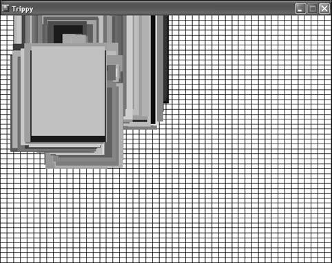
Figure 4.6. The Trippy program example uses rapidly drawn rectangles to achieve a psychedelic effect.
If you recall from the code, the Trippy program is smart enough to redraw the grid lines in the background if the window is minimized or resized, but it doesn’t take into account redrawing the rectangles. You can test this out by covering part of the window with another window, and then revealing the window again. The portion of rectangles not covered will be erased because of the repaint, but the part of the window that was visible will remain untouched. This redraw problem is not too difficult to fix. In fact, you solve the problem in Hour 5 when you build a slideshow program example using bitmap images.
This hour laid the groundwork for the game graphics that you develop and use throughout the remainder of the book. I know; you’re no doubt getting antsy because you’ve yet to touch on anything terribly game-specific. However, keep in mind that game programming, especially in Windows, involves a variety of different programming disciplines that must come together before a complete game can be built. Even so, hopefully you’re feeling a significant sense of accomplishment now that you know how to draw graphics with a little animated pizzazz using the GDI.
Hour 5 continues along in the exploration of GDI graphics programming by uncovering the most important game development concept: graphical images. You find out about bitmap images, how they work, and how to load and display them in a Windows program. You also put your image handling skills to work by creating a slideshow that you can use to display storyboards for your games, or maybe just pictures from your last vacation.
The Workshop is designed to help you anticipate possible questions, review what you’ve learned, and begin learning how to put your knowledge into practice. The answers to the quiz can be found in Appendix A, “Quiz Answers.”
Create a pen in a color of your choosing, and then use it in the
GamePaint()function of the Trippy program to draw grid lines in that color.Modify the random color values used for the brush in the
GameCycle()method of the Trippy program to see how different combinations work. For example, change the red component so that it is fixed at either0or255, and then shorten the range of the green or blue component.