Chapter 2. QoS Tools and Architectures
QoS Exam Topics
This chapter covers the following exam topics specific to the QOS exam:
![]() List and explain the models for providing Quality of Service on a network
List and explain the models for providing Quality of Service on a network
![]() Explain the purpose and function of the DiffServ model
Explain the purpose and function of the DiffServ model
![]() Describe the basic format of and explain the purpose of the DSCP field in the IP header
Describe the basic format of and explain the purpose of the DSCP field in the IP header
![]() Define and explain the different per hop behaviors used in DSCP
Define and explain the different per hop behaviors used in DSCP
![]() Explain the interoperability between DSCP-based and IP-precedence-based devices in a network
Explain the interoperability between DSCP-based and IP-precedence-based devices in a network
![]() Given a list of QoS actions, correctly match the QoS actions to mechanisms for implementing QoS and identify where in a network the different QoS mechanisms are commonly used
Given a list of QoS actions, correctly match the QoS actions to mechanisms for implementing QoS and identify where in a network the different QoS mechanisms are commonly used
To build a house, you need tools, you need materials, you need labor, and you need architectural plans. To build a network using quality of service (QoS), you need tools, labor, and an architecture. This chapter lists the various IOS QoS tools and explains the two predominant QoS architectures: integrated services (IntServ) and differentiated services (DiffServ).
Chapter 1, “QoS Overview,” covered various types of QoS tools. There are several different categories of QoS tools in Cisco IOS Software. This chapter begins by listing the tools in each category—at least the ones covered on the QOS exam. This first section also includes a brief introduction to concepts behind each type of tool. All the tools listed here get further treatment in later chapters of the book.
As a tool for learning, the second section of this chapter explains the basics of flow-based QoS tools and Class-Based QoS tools. Taking a few minutes to think about these concepts, and why they make sense, is useful before looking at the two formalized QoS models — namely DiffServ and IntServ.
Next, this chapter then examines the DiffServ architecture in detail. DiffServ attempts to provide Internet-scale QoS, which is a lofty goal indeed! DiffServ uses a Class-Based approach to differentiate between packets, which scales somewhat better than its predecessor, IntServ. Whether DiffServ succeeds in this goal remains to be seen; however, many of the concepts can be helpful with any QoS implementation.
Finally, the chapter ends with a short discussion on IntServ and Best Effort architectures. IntServ uses the Resource Reservation Protocol (RSVP) to reserve bandwidth for individual flows in the network. Best Effort is actually just a plan in which the network makes no real effort to give one type of packet better service than any other.
This chapter concludes the introductory materials in this book; the remainder of this book delves into the details of the various QoS tools.
The purpose of the “Do I Know This Already?” quiz is to help you decide whether you need to read the entire chapter. If you already intend to read the entire chapter, you do not necessarily need to answer these questions now.
The 12-question quiz, derived from the major sections in the “Foundation Topics” section of this chapter, helps you determine how to spend your limited study time.
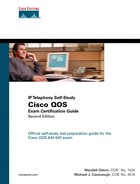
Table 2-1 outlines the major topics discussed in this chapter and the “Do I Know This Already?” quiz questions that correspond to those topics.
Caution The goal of self-assessment is to gauge your mastery of the topics in this chapter. If you do not know the answer to a question or are only partially sure of the answer, mark this question wrong for purposes of the self-assessment. Giving yourself credit for an answer you correctly guess skews your self-assessment results and might provide you with a false sense of security.
You can find the answers to the “Do I Know This Already?” quiz in Appendix A, “Answers to the ‘Do I Know This Already?’ Quizzes and Q&A Sections.” The suggested choices for your next step are as follows:
![]() 10 or less overall score—Read the entire chapter. This includes the “Foundation Topics,” the “Foundation Summary,” and the “Q&A” sections.
10 or less overall score—Read the entire chapter. This includes the “Foundation Topics,” the “Foundation Summary,” and the “Q&A” sections.
![]() 11 or 12 overall score—If you want more review on these topics, skip to the “Foundation Summary” section and then go to the “Q&A” section. Otherwise, proceed to the next chapter.
11 or 12 overall score—If you want more review on these topics, skip to the “Foundation Summary” section and then go to the “Q&A” section. Otherwise, proceed to the next chapter.
|
1. |
Which of the following are not Queuing tools? a. LLQ b. CBPQ c. CBWFQ d. CBCQ e. WRR |
|
2. |
Which of the following tools monitors the rate at which bits are sent out an interface? a. LLQ b. CB Shaping c. WRED d. CB Policing e. MLP LFI |
|
3. |
Which of the following tools can mark IP packet’s DSCP field? a. CB Marking b. WRED c. CB Policing d. MLP LFI e. NBAR |
|
4. |
Which of the following tools chooses to discard packets even though the router either has memory to queue the packets, or available physical bandwidth to send the packets? a. CB Marking b. WRED c. CB Policing d. MLP LFI e. NBAR f. ECN |
|
5. |
Which of the following are not used to identify a flow? a. ECN bits b. Source port c. Layer 4 protocol type d. Destination IP address e. TCP acknowledgment number |
|
6. |
Which of the following are likely places at which to mark packets in a network using good QoS design practices? a. In client PCs b. As close to the client as possible without allowing end users to mark packets c. As packets enter an SP from a customer network d. As packets enter the LAN switch to which the destination host is attached |
|
7. |
What does DSCP stand for? a. Diffserv Static Code Point b. Diffserv Standardized Configuration Process c. Differentiated Services Code Point d. Differentiated Services Configuration Point |
|
8. |
According to the DiffServ, which PHB defines a set of three DSCPs in each service class, with different drop characteristics for each of the three DSCP values? a. Expedited Forwarding b. Class Selector c. Assured Forwarding d. Multi-class-multi-drop |
|
9. |
Which of the following is true about the location of DSCP? a. High order 6 bits of ToS byte b. Low order 6 bits of ToS byte c. Middle 6 bits of ToS byte d. High order 5 bits in ToS byte |
|
10. |
Imagine a packet is marked with DSCP CS3. Later, a QoS tool classifies the packet. Which of the following classification criteria would match the packet, assuming the marking had not been changed from the original CS3 marking? a. Match of DSCP CS3 b. Match of precedence 3 c. Match on DSCP AF32 d. Match on DSCP AF31 e. Match on DSCP decimal 24 |
|
11. |
Imagine a packet is marked with AF31. Later, a QoS tool classifies the packet. Which of the following classification criteria would match the packet, assuming the marking had not been changed from the original AF31 marking? a. Match of DSCP CS3 b. Match of precedence 3 c. Match on DSCP AF32 d. Match on DSCP AF31 e. Match on DSCP 24 |
|
12. |
Which of the following are reasons why IntServ does not scale as well as DiffServ? a. Keeps flow state on each node b. Flow-based architecture c. Requires complex configuration for matching criteria for each possible flow d. Continuous signaling to maintain QoS reservation |
This chapter introduces the long list of QoS tools and two important QoS architectures—differentiated services (DiffServ) and integrated services (IntServ). You can think of QoS implementation as building a house. To properly build a house, you certainly need (and use) a large variety of tools. An experienced builder might be able to use the tools to build a house without an architectural plan. With the architectural plans, however, an experienced house builder can build a better house! Similarly, an experienced network engineer can use QoS tools with good results, without considering the DiffServ and IntServ architectures. By considering these architectures, however, a network engineer can use the tools to implement the QoS policies more consistently and efficiently, and thereby guarantee better QoS.
This chapter begins with an introduction to the various QoS tools in Cisco IOS Software. The next section covers some basic concepts about flows, service classes, and where you might use a tool in a network. Following coverage of these topics, the chapter examines the three major QoS models, with particular emphasis on DiffServ.
The next few pages introduce each class of QoS tool in a Cisco router as well as list the specific tools in each class. The specific classes of tools are as follows:
![]() Classification and marking
Classification and marking
![]() Congestion Management (Queuing)
Congestion Management (Queuing)
![]() Shaping and policing
Shaping and policing
![]() Congestion Avoidance
Congestion Avoidance
![]() Link-efficiency
Link-efficiency
![]() Call admission control (CAC)
Call admission control (CAC)
Ultimately, this book focuses on topics covered on the Cisco QOS exam. To that end, this section introduces the specific QoS tools covered on the exam, with specific focus on router-based QoS tools. Chapters 3 through 8 provide much more detail about each tool. Also, if there’s a QoS tool in router IOS that’s not listed here, and you want more information, you might look at the introduction to this book, which lists the contents of a CD-ROM-only appendix. That appendix, found on the CD-ROM in the back of this book, contains coverage from previous editions of this book for QoS tools that are no longer covered on the Cisco QOS exam.
Chapter 9, “LAN QoS,” covers the details of QoS tools on LAN switches.
Almost every QoS tool uses classification to some degree. To put one packet into a different queue than another packet, the IOS must somehow differentiate between the two packets. To perform header compression on RTP packets, but not on other packets, the IOS must determine which packets have Real Time Protocol (RTP) headers. To shape data traffic going into a Frame Relay network, so that the voice traffic gets enough bandwidth, the IOS must differentiate between Voice over IP (VoIP) and data packets. If an IOS QoS feature needs to treat two packets differently, you must use classification.
Classification involves differentiating one packet from another, typically by examining fields inside the headers. After classification, a QoS tool can treat packets in one class differently than others. To just give all VoIP traffic preference over all other traffic, the queuing tool would need to classify traffic into one of two categories: VoIP or not-VoIP.
Because most QoS tools need to differentiate between packets, most QoS tools have classification features. In fact, you may already know something about several of the QoS tools described in this book. You may realize that you already know how to perform classification using some of those tools. Many QoS tools enable you to classify using access-control lists (ACLs) — for instance, if ACL 101 “permits” a packet, the packet falls into one queue; if ACL 102 permits a packet, it is placed in a second queue; and so on. In one way of thinking, queuing could instead be called “classification and queuing,” because the queuing feature must somehow decide which packets end up in which queue. Similarly, traffic shaping could be called “classification and traffic shaping,” policing could be called “classification and policing,” and so on. Because most QoS tools classify traffic, however, the names of most QoS tools never evolved to mention the classification function of the tool.
Only one category of QoS tool, called classification and marking, highlights the classification feature in the name of the tool. For other tools, the classification function is just part of the story; with classification and marking tools, classification is the whole point of the tool. To appreciate the need for classification and marking tools, consider Figure 2-1. The figure shows the QoS policies for traffic flowing right to left. R3 performs queuing and shaping, and R2 performs queuing only. However, for both sets of queues, and for the shaping function, classification must occur. The classification part of the effort seems to be a simple task, but it may cause many comparisons to be made. For instance, each packet exiting R3’s S0 and R2’s S0 interfaces might be compared for the following:
![]() From source address 10.1.1.1, TCP source port 80 (Server1 web traffic)
From source address 10.1.1.1, TCP source port 80 (Server1 web traffic)
![]() Using User Datagram Protocol (UDP), port number range 16384 to 32767 (voice payload) — may also want to check IP address ranges to match IP Phones’ voice subnets, or voice gateway IP addresses
Using User Datagram Protocol (UDP), port number range 16384 to 32767 (voice payload) — may also want to check IP address ranges to match IP Phones’ voice subnets, or voice gateway IP addresses
![]() Using TCP port 1720 (H.323 voice signaling)
Using TCP port 1720 (H.323 voice signaling)
![]() Using TCP port range 11000 to 11999 (Voice signaling)
Using TCP port range 11000 to 11999 (Voice signaling)
![]() Using TCP port 1719 (Voice signaling)
Using TCP port 1719 (Voice signaling)
![]() Using TCP port 2000 to 2002 (Skinny voice signaling)
Using TCP port 2000 to 2002 (Skinny voice signaling)
![]() Using UDP port 2427 and 2428 (MGCP voice signaling)
Using UDP port 2427 and 2428 (MGCP voice signaling)

Classification and marking tools simplify the classification process of the other QoS tools. Even with seemingly simple requirements, the classification functions can require many comparisons to every packet. Rather than have each tool do extensive packet matching, classification and marking tools do the extensive classification once, and mark a field in a packet header. The remaining QoS tools just need to look for this marked field, simplifying the repetitive classification work.
The two most commonly used marking fields in the IP header are the IP Precedence field, and the Differentiated Services Code Point (DSCP) field. You will see the details of these two fields, along with the other fields that can be used for marking, later in this chapter. Consider Figure 2-2, where classification and marking is performed on input of R3.

The queuing and shaping features can now classify more efficiently. Queuing is still performed on R3 and R2, and shaping is still performed on R3. However, the extensive matching logic for each packet done for all incoming traffic can be performed once on R3’s FA0/0 interface, or once on one of the LAN switches, such as SW3. Once marked, the other QoS tools can react to the marked value, which each QoS tool can efficiently match in the end-to-end path through the network.
A variety of classification and marking tools exist. Classification and marking tools first classify by looking at something inside each packet; you can compare these tools by listing the fields the tool can examine. Classification and marking tools mark the frame or packet based on the earlier comparisons; you can compare these tools by listing the fields that can be marked. Some classification and marking tools also perform other functions, as noted in Table 2-2.

Chapter 4, “Classification and Marking,” explains the details of each of the tools, all the marked fields, and the configuration of each tool.
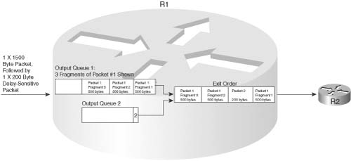
Queuing, frequently called Congestion Management in Cisco documents, and also occasionally called “scheduling,” provides the ability to reorder packets when congestion occurs. Whereas queuing sometimes occurs at the ingress interface, called “input queuing,” most queuing methods implement only output queuing. The general idea is simple, but the details can be a little overwhelming. Consider Figure 2-3, with a simple two-queue output queue system.

In the figure, four packets arrived in order, at about the same time. The queuing tool’s classification feature classified packets 1 through 3 as belonging in Queue 1, and packet 4 as belonging in Queue 2. The figure implies that Queue 2 should receive 75 percent of the bandwidth. But which packet is sent next? In what order do these four packets leave the router? If packet 5 shows up a little later, could it be sent before some of packets 1 through 4? Could the tool support more than two queues? Well, the answers to these questions define the key comparison points between the various queuing tools. You should look for the following when comparing queuing tools:
![]() Classification capabilities, particularly the packet header fields that can be matched to classify a packet into a particular queue. In some cases, the queuing tool automatically classifies traffic, whereas other tools require you to configure the values to be matched in the packets explicitly.
Classification capabilities, particularly the packet header fields that can be matched to classify a packet into a particular queue. In some cases, the queuing tool automatically classifies traffic, whereas other tools require you to configure the values to be matched in the packets explicitly.
![]() The maximum number of queues (sometimes called the maximum number of classes). If you need to distinguish between x different types of traffic for queuing, you need at least x queues.
The maximum number of queues (sometimes called the maximum number of classes). If you need to distinguish between x different types of traffic for queuing, you need at least x queues.
![]() The scheduling algorithm. For some queuing tools, Cisco publishes the algorithms used to decide what packet is taken from which queue next; for other tools, Cisco publishes the net effect of the algorithm. In either case, you can still make a good choice as to which tool to use.
The scheduling algorithm. For some queuing tools, Cisco publishes the algorithms used to decide what packet is taken from which queue next; for other tools, Cisco publishes the net effect of the algorithm. In either case, you can still make a good choice as to which tool to use.
Ultimately, you use these queuing features, and other less-obvious features, when choosing the right queuing tool for a particular need in a particular network.
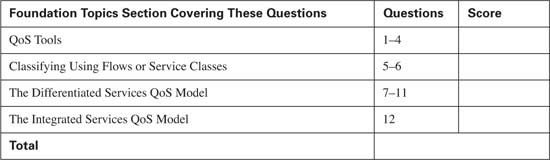
QoS queuing tools provide you with a variety of queuing methods. Queuing tools define a number of queues. Cisco publishes the queue service algorithm in some cases; in others, Cisco publishes only the end result (the “what”), but not the algorithm (the “how”). Table 2-3 outlines the key features of IOS queuing methods.
Chapter 5, “Congestion Management,” covers each of the queuing tools in detail.
Because shaping and policing provide two different functions, you may wonder why shaping and policing are covered here at the same time. The simple answer is this: Networks that use policing typically need shaping as well. Also both shaping and policing measure the rates at which traffic is sent and received in a network, so some of the underlying features are similar. Both can be described using similar metaphors of “token buckets.” Finally, from a business perspective, shaping and policing are typically implemented at or near the edge between an enterprise and a service provider. Therefore, when considering whether you need to use one type of tool, you need to be thinking about the other type.
Traffic shaping, or shaping, delays packets by putting packets in a queue, even when real bandwidth is available. It’s like being at the bank. A teller finishes with a customer, and you’re next in line. You have to wait another minute or two, however, while the teller finishes doing some paperwork for the preceding customer. Why would a router ever want to delay packets? Well, the short answer is “because delaying these packets is better than what happens if you don’t delay them.” Figure 2-4 shows just one example where shaping is useful.

This example results in a large queue forming at Frame Relay Switch 2 (FRS2) due to the speed mismatch between the access links at R2 and R3. In this example, 50 1500-byte packets arrive over R3’s Ethernet during a 500-ms span, needing to be delivered to R2. If all 50 packets were to arrive one after the other, with no gaps, a queue would form on R3’s S0 interface. Because it takes a little less than 10 ms to send a 1500-byte packet over T/1, however, all 50 packets would drain from the queue within that 500 ms.
However, because the access link between FRS2 and R2 clocks at 128 kbps, it takes almost 100 ms to serialize a 1500-byte packet. So, although some queuing happens at R3, FRS2’s egress queue on the link to R2 fills — in this case, it needs to be 45 packets long. (Five packets could be sent over this link during the 500 ms that the rest of the packets are arriving.)
What happens if FRS2’s maximum egress queue size is only 20 frames? In such a scenario, around half of the frames are discarded. What is the impact? The quality of voice and video streams degrades. Most data applications resend their data — which may well cause the same phenomena all over again. Both results, of course, are bad.
Traffic shaping solves this particular problem. If R3 had just waited and sent one 1500-byte packet every 100 ms, because FRS2 can send one 1500-byte packet in a little less than 100 ms, no queue would have formed on FRS2’s egress interface. Even if R3 were to send one 1500-byte packet every 50 ms, FRS2’s egress queue would grow, but only a few packets would be lost.
Whenever a speed mismatch occurs, shaping may be able to reduce the chance that packets get dropped. In the previous example, a speed mismatch occurred on the access rates of two Frame Relay-connected routers. In other cases, it may be that many VCs terminate at one router, and the collective VC committed information rates (CIRs) far exceed the access rate (oversubscription). In either case, queues may form, and they may form in a place where the engineer cannot control the queue—inside the Frame Relay cloud.
Shaping may help in one other specific case: when the Frame Relay service provider uses policing. The service provider may need to limit a VC to use just the CIR amount of bandwidth. Most providers, as well as their customers, expect the Frame Relay data terminal equipment (DTE) to send more than the CIR across each VC. However, the provider may decide that in this case, they need to prevent R3 and R2 from sending more than CIR. Why? For many reasons, but one common reason may be that a particular part of their network may have enough capacity to support the CIRs of all VCs for all customers, but not much bandwidth beyond that. To protect customers from each other, the provider may limit each VC to CIR, or some percentage over CIR, and discard the excess traffic.
The QoS tool used to monitor the rate, and discard the excess traffic, is called traffic policing, or just policing. Because the provider is monitoring traffic sent by the customer, traffic policers typically monitor ingress traffic, although they can monitor egress traffic as well. Figure 2-5 shows the same network, but with policing and shaping enabled for traffic entering FRS3 from R3.

In the shaping discussion, one solution involved sending only one 1500-byte packet every 100 ms, which prevented an egress queue from forming on FRS2. As seen in this figure, however, the ingress policer on FRS3 monitors incoming traffic on the VC from R3 to R2, allowing only one 1500-byte packet per 200 ms. Policers discard the excess traffic, which in this case, even with shaping enabled on R3, half of the packets will be discarded when the network is busy! The solution, when the provider enables policing, is to configure shaping such that R3 only sends traffic at a rate that the policer function allows. In summary, some of the reasons behind shaping and policing are as follows:
![]() Packets might be lost in a multiaccess WAN due to access rate speed mismatch, oversubscription of CIRs over an access link, or by policing performed by the provider.
Packets might be lost in a multiaccess WAN due to access rate speed mismatch, oversubscription of CIRs over an access link, or by policing performed by the provider.
![]() Traffic shaping queues packets when configured traffic rates are exceeded, delaying those packets, to avoid likely packet loss.
Traffic shaping queues packets when configured traffic rates are exceeded, delaying those packets, to avoid likely packet loss.
![]() Traffic policing discards packets when configured traffic rates are exceeded, protecting other flows from being overrun by a particular customer.
Traffic policing discards packets when configured traffic rates are exceeded, protecting other flows from being overrun by a particular customer.
Cisco IOS provides several options for shaping and policing tools. As usual, you may consider many factors when comparing these tools. (Table 2-4 lists a few of these factors.) First, not all shaping and policing tools support every data-link protocol. Second, some tools can be enabled on a subinterface, but not on a per data-link connection identifier (DLCI); therefore, in cases where a network uses multipoint subinterfaces, one tool may give more granularity for shaping/policing. With regard to policers, some categorize packets as either conforming to or exceeding a traffic contract (called a two-headed policer), and some categorize packets as either conforming to, exceeding, or violating a traffic contract (a three-headed policer).

Chapter 6, “Traffic Policing and Shaping,” covers each of the policing and shaping tools in detail.
When networks become congested, output queues begin to fill. When new packets need to be added to a full queue, the packet is dropped—a process called tail drop. Tail drop happens in most networks every day—but to what effect? Packet loss degrades voice and video flows significantly; for data flows, packet loss causes higher-layer retransmissions for TCP-based applications, which probably increases network congestion.
Two solutions to the tail-drop problem exist. One solution is to lengthen queues, and thereby lessen the likelihood of tail drop. With longer queues, fewer packets are tail dropped, but the average queuing delay is increased. The other solution requires the network to ask the devices sending the packets into the network to slow down before the queues fill — which is exactly what the Congestion Avoidance QoS tools do.
Congestion Avoidance tools operate under the assumption that a dropped TCP segment causes the sender of the TCP segment to reduce its congestion window to 50 percent of the previous window. If a router experiences congestion, before its queues fill completely, it can purposefully discard several TCP segments, making a few of the TCP senders reduce their window sizes. By reducing these TCP windows, these particular senders send less traffic into the network, allowing the congested router’s queues time to recover. If the queues continue to grow, more TCP segments are purposefully dropped, to make more TCP senders slow down. If the queues become less congested, the router can stop discarding packets.
This book covers three Congestion Avoidance tools. One of the tools was never implemented in IOS (Random Early Detection, or RED)—but because the other two features are based on RED concepts, Chapter 7, “Congestion Avoidance Through Drop Policies,” covers the basics of RED as well.
All Congestion Avoidance tools consider the queue depth—the number of packets in a queue—when deciding whether to drop a packet. Some tools weigh the likelihood of dropping a packet based on the IP precedence or IP DSCP value. One Congestion Avoidance tool doesn’t actually discard packets but instead uses bits in the IP and TCP header to signal to the TCP sender asking it to slow down. Table 2-5 lists the tools and the various points for comparison.

Chapter 7 covers each of the Congestion Avoidance tools in detail.
The category of link efficiency encompasses two related topics: compression and fragmentation. Rather than treat these topics in two separate chapters, I have included them in one chapter (Chapter 8, “Link Efficiency Tools”) to match the organization of the Cisco QOS courses (and the IOS documentation to some degree).
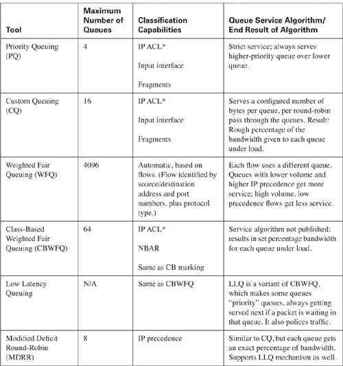
Compression reduces bandwidth utilization by making packets smaller before transmission. Two general types of compression tools exist in IOS—payload compression and header compression. Payload compression compresses the “packet”—the portion of the data link frame between the frame header and trailer. Header compression compresses just particular headers. Figure 2-6 shows the typical scope of the compressed portions of a frame over a PPP link.
Compression tools differ in how much CPU load they create and which parts of the frame they compress. Based on the CPU load and what is compressed, you can make good decisions about when to use each tool.
Payload compression can be applied to all packets, with some good results. Suppose that the compression algorithm manages to compress x bytes of payload into half that size—a reasonable 2:1 compression ratio. The router saves a lot of bandwidth with the compression a 1500-byte packet into a 750-byte packet. Given the variation and unpredictable nature of the contents of the packets, compression ratios between 2:1 and 4:1 are reasonable with payload compression.
Header compression takes advantage of the fact that the headers being compressed are predictable. Much larger compression ratios can be achieved, many times with less CPU load than payload compression. However, header compression only operates on headers. For instance, compressed RTP compresses packets with IP/UDP/RTP headers, as shown in Figure 2-6. The 40 bytes of the IP/UDP/RTP headers compress to between 2 and 4 bytes. For a minimum packet size of 60 bytes, typical of G.729 VoIP calls, cRTP reduces the packet from 60 bytes to between 22 to 24 bytes, a significant improvement. However, head compression does not provide much benefit for larger packets, because the headers make up such a small percentage of the packets.
The other major category of link-efficiency tools is link fragmentation and interleaving (LFI), also just called fragmentation. The concept is simple: When a router starts sending a packet, it never just stops sending that packet in order to send a higher-priority packet—it finishes sending the first packet, and then sends the higher-priority packet. On slow links, the time it takes for one large packet to be serialized may cause too much delay, particularly for VoIP and video traffic. LFI tools fragment large packets into smaller packets, and then interleave the high-priority packet between the fragments. For instance, it takes 214 ms to serialize one 1500-byte packet over a 56-kbps link, which blows the VoIP one-way delay budget. (As described in Chapter 8, Cisco recommends that you considered LFI when the link speed is 768 kbps or less.) Figure 2-7 shows the process of fragmentation.
Without LFI, packet 2 has to wait 214 ms on the 1500-byte packet. With LFI fragmenting packet 1 into three parts, the serialization delay is reduced to about 72 ms.
Most link-efficiency tools have a specific application that becomes obvious when you discover what each tool can and cannot do. Not all compression and LFI tools support every type of data link. Both compression and LFI tools may operate on a subset of the packets that exit an interface. For instance, TCP header compression just compresses IP packets that also have TCP headers. Frame Relay fragmentation only operates on a subset of the packets, based on which of two styles of fragmentation is configured. So depending on what you want to accomplish with link efficiency, you can typically use a single tool. Table 2-6 lists the link- efficiency tools and some of the pertinent comparison points.

Chapter 8 covers each of the link-efficiency tools in detail.
Call admission control (CAC) protects network bandwidth by preventing more concurrent voice and video flows than the network can support. By doing so, it not only protects data traffic, but it also protects the quality of voice and video calls that are already set up. If a network engineer designs a network to support 3 concurrent G.729 calls, for instance, which take roughly 85 kbps, depending on the data links used, but if 10 concurrent calls occur, taking roughly 285 kbps, many bad things happen. Data applications may not get enough bandwidth. Also all the voice calls tend to degrade quickly—not just the “extra” calls.
The current Cisco QOS exam does not cover CAC tools; however, if you want more information, Appendix C, “Voice Call Admission Control Reference,” (found on the book’s accompanying CD-ROM) contains the CAC chapter from the previous edition of this book. Also, you will want to search for information at cisco.com, particularly about a Cisco CallManager feature called “locations,” which is an effective CAC tool when deploying Cisco IP Telephony.
If you do not work with QoS tools every day, and you are reading this book to pass one of the Cisco QOS exams, you might be feeling overwhelmed after reading the first section of this chapter! However, do not be dismayed—the remaining chapters in this book are devoted to a deeper description of the tools introduced here. Even if most of the tools listed in this chapter so far are new to you, by the time you read the detail, you’ll probably have memorized the names of the tools.
Next, you’ll read about a few background concepts before diving into the detail of how DiffServ works.
Before covering the depth and details in the upcoming chapters, you should consider some basic terms, concepts, and strategies for applying QoS in a network. The next few pages covers a few more concepts and terms that can help you better appreciate the two major QoS architectural models, namely DiffServ and IntServ. In particular, you should have a good understanding of the difference between flow-based QoS tools and Class-Based QoS tools. This short section takes a closer look at both.
A flow consists of all the packets about which the following are true:
![]() All packets use the same transport layer protocol (for instance, UDP or TCP).
All packets use the same transport layer protocol (for instance, UDP or TCP).
![]() All packets have the same source IP address.
All packets have the same source IP address.
![]() All packets have the same source port number.
All packets have the same source port number.
![]() All packets have the same destination IP address.
All packets have the same destination IP address.
![]() All packets have the same destination port number.
All packets have the same destination port number.
The slightly different, but just as exact definition, is that a flow consists of the packets between two IP sockets. For instance, a web browser on a PC, connecting to a server, creates a flow. (Actually, in the case of HTTP, it may create multiple TCP connections, which would actually be multiple flows.) Regardless, consider Figure 2-8. In this network, one flow exists from Hannah to Server1’s web server.

The single flow shown in the figure consists of the packets sent by Hannah to Server1. Note that flows are unidirectional—in effect, two flows, one in each direction, would exist. To reduce the complexity, the samples in this section show flows going left to right only.
Flow-based QoS tools behave like the logic shown in the figure. These QoS tools recognize flows and treat packets in one flow differently than another flow. So, common sense may imply that the QoS tools must first identify the packets that belong to this single flow, and then take some QoS action—such as queuing, LFI, shaping, and so on—for the packets in that flow. The tools may be applied for packets entering an interface, and other QoS tools may be applied for packets exiting an interface. Some tools may even be applied on the LAN switches. Some QoS tools may be applied in the Frame Relay cloud—but those are not typically under your control.
Real networks will have a widely varying number of flows, but the general ideas behind flow-based QoS tools do not change when more flows exist. Take a look at Figure 2-9, which shows a fairly small network with only four flows at this point.

This figure shows four flows. Even though Vinnie sends all packets for both flows to Server1, they are in two different flows, because each of the two browser windows would open separate TCP connections, with different source TCP port numbers. (Note: HTTP 1.1 could cause multiple connections to be opened; FTP uses a control and data connection, which would result in two flows.) However, assume that only four flows exist at this point.
Flow-based QoS tools identify each and every flow based on its unique source/destination address/ port values. The QoS actions at each router may be different for each flow—for instance, maybe FTP just gets leftover bandwidth, or maybe Hannah gets better treatment for her web flow than does Vinnie. The reasons and rationale behind deciding what traffic gets what QoS treatment will change from network to network, but the basic process works the same:
![]() Identify each packet, determining which flow it belongs to.
Identify each packet, determining which flow it belongs to.
![]() Apply some QoS action to the packets in each flow.
Apply some QoS action to the packets in each flow.
![]() The QoS actions on a single router may be different for each flow.
The QoS actions on a single router may be different for each flow.
![]() The QoS actions among all routers may be different for each flow.
The QoS actions among all routers may be different for each flow.
Flow-based QoS tools provide some advantages and some disadvantages. Because each separate flow is identified, the QoS tools can literally provide different levels of service to every flow. A single queue could be used for each flow, for instance, giving each a different reserved bandwidth. With a large number of flows, however, the overhead associated with keeping state information about each flow can be a lot of work. Imagine a router with 1000, or even 10,000, concurrent flows, which would not be surprising in the Internet—and then imagine the overhead in trying to perform queuing with 1000 or 10,000 queues! So, flow-based QoS tools provide a great deal of granularity, but they do not scale as well as some other QoS tools that do not consider flows (particularly with very large networks or the Internet).
Engineers gain another advantage and disadvantage when configuring flow-based QoS tools. Suppose that your job is to explicitly configure the routers in Figure 2-9 as to which source and destination IP addresses and ports to use to find each flow. And instead of 4 flows, there are 1000 concurrent flows. Over the course of a day, there may be hundreds of thousands of flows. Your job is to find the details that make each flow unique and configure it! Well, that would be rather ridiculous, a lot of work, and mostly impractical. Therefore, flow-based tools typically require no configuration to match and classify packets into a flow. However, some configuration control is lost.
The following list summarizes the key points about flow-based QoS tools:
![]() Flow-based QoS tools automatically recognize flows based on the source and destination IP address and port numbers, and the transport layer protocol.
Flow-based QoS tools automatically recognize flows based on the source and destination IP address and port numbers, and the transport layer protocol.
![]() Flow-based tools automatically identify flows, because it would be impractical to configure parameters statically to match the large number of dynamically created flows in a network.
Flow-based tools automatically identify flows, because it would be impractical to configure parameters statically to match the large number of dynamically created flows in a network.
![]() Flow-based tools provide a great amount of granularity, because each flow can be treated differently.
Flow-based tools provide a great amount of granularity, because each flow can be treated differently.
![]() The granularity may create scaling problems when the number of flows becomes large.
The granularity may create scaling problems when the number of flows becomes large.
Most QoS tools do not need to differentiate between each flow; instead, they characterize packets into one or more service classes. In Figure 2-9, for instance, flows to web Server1 were identified. Most network engineers would want to treat those collective web flows the exact same way with their QoS tools. Therefore, most QoS tools tend to operate on the idea of a category, or service class, of flows and packets. Consider Figure 2-10, for example, which has thousands of flows, all of which are classified into four types of traffic.

Class-Based QoS tools do not have to identify each flow. However, they do need to identify packets based on something in the packet header—such as TCP destination port 80 for web traffic—and consider that traffic to be in one category or class for QoS treatment. Once again, the reasons and rationale behind deciding what traffic gets what QoS treatment changes from network to network, but the basic process works the same, but per class rather than per flow:
![]() Identify each packet, determining which class it belongs to.
Identify each packet, determining which class it belongs to.
![]() Apply some QoS action to the packets in each class.
Apply some QoS action to the packets in each class.
![]() The QoS actions on a single router may be different for each class.
The QoS actions on a single router may be different for each class.
![]() The QoS actions among all routers may be different for each class.
The QoS actions among all routers may be different for each class.
Unlike flow-based QoS tools, Class-Based QoS tools typically require the engineer to specify exactly what must be seen in the packet header to classify a packet. If this network currently has 4 flows to the web server, or 400, or 4000, if the classification criteria just states “all TCP port 80 traffic,” no additional configuration is required as the network scales. Both flow-based and Class-Based tools need to examine every packet to classify the packet into the appropriate flow or class. Because Class-Based tools typically only need a small number of classifications, however, the tool can reasonably be configured to specify the types of traffic that get added to each class.
Class-Based QoS tools can use more complex rules to classify packets than do flow-based tools. For instance, a Class-Based tool can examine subsets of the IP addresses (matching a subnet, for example), the incoming interface, the URL for web traffic, and anything that an IP ACL can match. For flow-based tools, the router always look at five fields, all in the IP header—Source and Destination Address, Source and Destination Port, and the Protocol Type field (which identifies the transport layer protocol). In short, classification options for Class-Based tools tend to be much more varied and functional, but they require more configuration work to take advantage of the different options.
Flow-based and Class-Based QoS tools both have a useful place in a QoS strategy for a network. Most QoS tools tend to be based on general classes, as opposed to looking at each individual flow.
Enterprise networks can take advantage that all routers and switches resident at the Enterprise’s physical locations. Through good QoS design, you can solve the problem of having every router in the network examining a lot of fields in every packet header. This design choice reduces the complexity of the configurations as well. Packets can be classified and marked near the ingress points of traffic into the network; the QoS tools in the center of the network can look for the marked field in the packet header, as shown in Figure 2-11.
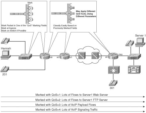
One of the most important design goals for Enterprise QoS is to enable Classification and marking near the edge of the network. Doing so simplifies the classification logic and configuration at the rest of the routers in the network. For instance, the figure shows the same classes as Figure 2-10, but with classification and marking performed near the ingress edge of the network. Ideally, packets should be marked even before they reach the first router, typically by a LAN switch. If not, packets entering R1’s E0 interface can be classified and marked. R1, R2, and R3 all still need to classify packets, but now the classification details just look for a single well-known field inside the IP header. (Note: The two IP header fields used are the IP Precedence and IP DSCP fields.) This design choice simplifies the QoS configuration and reduces the processing effort for the intermediate routers. (Note: Classification and marking can happen in the switches, IP Phones, and end-user computers—all of which are discussed in detail in Chapter 4, “Classification and Marking.”)
It is possible to plan QoS classes for an enterprise network. However, planning service classes for all networks in the Internet is a bit more challenging. For instance, although everyone may agree that VoIP and video may need different treatment than data, they probably do not agree about differentiation between different types of data traffic. Also, a company paying a premium to a service provider may expect better service—translated, better QoS treatment—so the classification may be based on the source IP addresses, and may be different for different ISPs.
Therefore, although the political and business challenges of Internet-scale QoS might be difficult, cases will still exist where QoS can be implemented over the Internet. Many ISPs today provide service differentiation for customers, allowing the customer to specify what types of traffic get better QoS service. Consider Figure 2-12, which shows two companies, each connected to two different ISPs.

Two key QoS issues exist in this case. First, the parties must agree to the different classifications of packets. In this example, all four networks agree to the need for four classes. (Agreement will not always occur with multiple ISPs!) For instance, McCoy Enterprises may want a different class for customer web traffic versus supplier web traffic, but other companies might want to treat all web traffic equally. Even if all companies want these same general categories, it is difficult to effectively match the correct traffic for all companies connected to the Internet, because every company has different customers and suppliers. Therefore, QoS across the Internet may well end up using general categories—categories such as voice, video, voice/video signaling, important data, and not-so-important data.
Even with general categories agreed upon, not every network chooses to mark the IP packets with the same value to denote the same service class. Figure 2-12 shows just such a case, where ISP1 and ISP2 agree to the values to use when marking packets, but McCoy Ordinance and Hatfield Gunsmiths, two long-time competitors, do not agree on what marked values to use.
Three commonsense QoS design choices help overcome common Internet QoS issues:
![]() If neighboring autonomous systems do not agree about what traffic should be in each class, each autonomous system should reclassify ingress traffic based on more complex matching of packets based on the large variety of packet header fields.
If neighboring autonomous systems do not agree about what traffic should be in each class, each autonomous system should reclassify ingress traffic based on more complex matching of packets based on the large variety of packet header fields.
![]() If neighboring autonomous systems do agree about the classes, but not the marked values, each autonomous system should reclassify ingress traffic based on simple matching of packets based on the previously marked fields in the IP header, as shown in Figure 2-13.
If neighboring autonomous systems do agree about the classes, but not the marked values, each autonomous system should reclassify ingress traffic based on simple matching of packets based on the previously marked fields in the IP header, as shown in Figure 2-13.
![]() If an autonomous system does not trust its neighbor regarding QoS, neighboring autonomous systems should also reclassify traffic at ingress, based on detailed matching of packets.
If an autonomous system does not trust its neighbor regarding QoS, neighboring autonomous systems should also reclassify traffic at ingress, based on detailed matching of packets.

The section that follows disusses Differentiated Services, also known as DiffServ, the first of two QoS architectures that you will read about. DiffServ formally defines the concept of service classes and re-marking packets as packets pass between autonomous systems.
Differentiated Services, also known as DiffServ, takes many of the common sense concepts you’ve already read about, and formalizes them into a cohesive architecture for applying QoS. The RFCs that define DiffServ go into a lot more depth than you will read here, but the core concepts of DiffServ can be summarized as follows:
![]() Takes advantage of the scaling properties of Class-Based QoS tools to differentiate between types of packets, with the goal of “scalable service differentiation in the Internet.”
Takes advantage of the scaling properties of Class-Based QoS tools to differentiate between types of packets, with the goal of “scalable service differentiation in the Internet.”
![]() In a single network, packets should be marked at the ingress point into a network, with other devices making QoS choices based on the marked field.
In a single network, packets should be marked at the ingress point into a network, with other devices making QoS choices based on the marked field.
![]() The marked field will be in the IP header, not a data-link header, because the IP header is retained throughout the network.
The marked field will be in the IP header, not a data-link header, because the IP header is retained throughout the network.
![]() Between networks, packets can be reclassified and re-marked at ingress into another network.
Between networks, packets can be reclassified and re-marked at ingress into another network.
![]() To facilitate marking, the IP header has been redefined to include a 6-bit Differentiated Services Code Point (DSCP) field, which allows for 64 different classifications.
To facilitate marking, the IP header has been redefined to include a 6-bit Differentiated Services Code Point (DSCP) field, which allows for 64 different classifications.
To some extent, DiffServ formally defines a QoS architecture using common sense, or “best practices,” for QoS design today. Along with the formal definitions comes a lot of terminology—terminology that is purposefully vendor neutral. So, after learning the DiffServ terms, you need to relate them to Cisco tools and terms. But DiffServ is more than just recording some good ideas about QoS—DiffServ defines another useful field in the IP header (DSCP), as well as some conventions for usage of the new DSCP field. Finally, DiffServ defines general categories of QoS functions and the purpose of the tools in each category. This book has already covered those same concepts and terms from the Cisco perspective, so in this section, you will read about the DiffServ terms for categories or types of QoS tools and how they relate to Cisco terms.
DiffServ is defined by the RFCs listed in Table 2-7.

The RFCs introduce many new terms. Table 2-8 lists the terms and their definitions. This table provides a reference for study for the Cisco QOS exam; the rest of this section relates the terms to some network diagrams.


*Table 2-8 material reprinted from RFC 2475
DiffServ terminology overwhelms most people when first learning the architecture. Not all the DiffServ terms are even listed in the table. In fact, I wouldn’t be surprised if you are already wondering which of these terms you really need to know when using QoS and which of these terms you need to know for the Cisco QOS exam. The exam does not focus on DiffServ as an end to itself. If you glance over the table, and read this section, you should become familiar enough with the terms to do well on those questions on the exams. It certainly isn’t worth the effort to memorize all the terms in Table 2-8; the table is just included for reference.
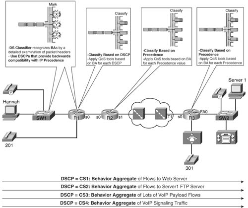
The rest of this section explores some examples of usage of DiffServ terminology. The first two terms are “behavior aggregate” and “per-hop behavior.” If you read the previous section you already know the concepts behind the terms. Figure 2-13 shows the terms in a figure that is a duplicate of Figure 2-11.
Consider the flow of packets from left to right in this network. The following list numbers correspond to the steps in the figure:
1. The packets are classified or categorized by matching fields in the header. For instance, packets with Server1’s destination IP address, and destination port 80, would be in the first class. The process of classifying the packets is performed by the DS classifier, MF classifier, or just classifier. The classifier marks the DSCP field inside the IP header; DSCP is a 6-bit field inside the DS field (byte) inside the IP header. Classification and marking are considered to be two different steps—the DiffServ marker actually performs the process of marking the packets. DiffServ defines each class or category of packets as a BA.
2. Router R1 determines which packets are part of which BA by using a BA classifier. A BA classifier only examines the DSCP field, so technically it differs from an MF classifier, as described in step 1, because the MF classifier can look at many fields besides the DSCP field. When R1 decides to apply a QoS tool to a BA (for example, queuing), the action is called a per-hop behavior. The term PHB makes sense to most people, particularly if you think of it as a per-hop QoS behavior.
3. Router R2 performs the same types of tasks as R1; these tasks are described with the same terms as in step 2. Also note that the PHBs can be, and often are, different on one router to the next. In this case, R2 may want to use a shaping PHB—DiffServ would call the shaping tool a shaper—but because all implemented shaping tools need to calculate the rate at which packets are sent, DiffServ would consider both a meter and shaper to be used.
4. Likewise, no new terminology is required to describe step 4, as compared with the two preceding steps. However, the terms “AF11,” “AF21,” “AF31,” and “AF41” have not yet been defined. DiffServ defines several suggested values to be used in the DSCP field. Most installations do not need all 64 values possible in DSCP. The next section in this chapter covers the details, but in this case, AF11, AF21, AF31, and AF41 represent four different DSCP values.
DiffServ models good QoS design specifically to support Internet-scale QoS. Reading through the RFCs, you will notice that DiffServ focuses on issues between different networks. Figure 2-14 shows the same two enterprise networks and the same two ISPs shown in Figure 2-12 earlier in this chapter. The figure shows examples of several of the DiffServ terms that relate to interconnecting networks.
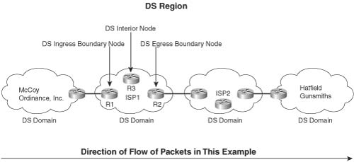
The terms in this figure only apply in cases where multiple organizations’ networks are interconnected. The entire figure comprises one DS region, which includes connected networks that are providing differentiated services. Each individual network, typically an autonomous system, is a single DiffServ domain.
The remaining terms in the figure relate to the particular direction of flow of the packets. In this figure, packets flow left to right. Therefore, R1 is a DS ingress boundary node, because it is on the boundary between two domains, and packets first enter the DS domain through R1. Similarly, R2 is a DS egress boundary node. R3 is a DS interior node, because it is not on the boundary of the network. Ingress and egress DS boundary nodes typically perform reclassification and re-marking work.
By this point, you might be wondering about all this new jargon with DiffServ. So far, this section has introduced you to many of the specific formal terms used with DiffServ. The next two sections examine two important aspects of DiffServ more closely, namely the DSCP field and the different types of PHBs. These two topics are certainly the most important DiffServ topics for the exam. As described so far, DiffServ operation can be summarized as follows:
1. Good planning must be performed to define the BAs needed for a network.
2. To mark packets to signify what BA they belong to, DiffServ suggests using MF classifiers, which can look at all fields in the packet header.
3. The classifier should be used near the ingress point of the network to assign unique DSCP values to packets inside each BA.
4. After marking has occurred, interior DS nodes use BA classifiers. BA classifiers only look at the DSCP field. When the BA is identified, that node’s PHBs can take action on that packet.
5. The ingress DS boundary node in a neighboring downstream DS domain network may not trust the neighboring upstream DS domain at all, requiring an MF classifier and marker at the DS ingress boundary node to reclassify and re-mark all traffic.
6. If the ingress DS boundary node trusts the neighboring DS domain, but the domains use different DSCP values for the same BA, a BA classifier function can be used to reclassify and re-mark the ingress traffic.
Other than the general QoS strategies described in this chapter, DiffServ really provides two additional key features: the DSCP field, and some good suggestions on how to use the DSCP field. In fact, two of the DiffServ RFCs, 2597 and 2598, are devoted to describing a set of DSCP values, and some suggested PHBs that should be associated with each DSCP value.
IP defined a type of service (ToS) byte in RFC 791, which came out in September 1981. The IP protocol creators intended the ToS byte to be used as a field to mark a packet for treatment with QoS tools. Inside the ToS byte, the first 3 bits were defined as a field called IP Precedence, which can be marked for the purposes of implying a particular class of service. The Precedence field values imply that the larger the value, the more important the traffic. In fact, names were given to each value 0 from routine (precedence 0) to critical (precedence 5) and network control (precedence 7). The complete list of values from the ToS byte’s original IP Precedence 3-bit field, and the corresponding names, are listed in Table 2-9.

In addition to the Precedence field, the ToS byte included other flag fields that were toggled on or off to imply a particular QoS service—for instance, low or high delay would be signaled by a 1 or a 0 in the delay bit. Bits 3 through 5 (RFC 795) comprised the ToS field inside the ToS byte, with flags for throughput, delay, and reliability. RFC 1349 expanded the ToS field to bits 3 through 6, adding a cost flag. For instance, the original ToS byte creators envisioned the ability to choose a different route, using a more reliable link, for packets with the reliability flag set.

The DS field redefines the ToS byte in the IP header. It removes the definition of the 4 ToS bits (bits 3 through 6). DiffServ creates a replacement for the Precedence field with a new 6-bit field called the Differentiated Services (DS) field. (The last 2 bits of the ToS bytes are used as flow control bits with the Explicit Congestion Notification (ECN) feature, as specified by RFC 3168.) Figure 2-16 shows the fields inside the ToS byte (per RFC 1349) and the DS field (per RFC 2474).
Changing a protocol that is used in production may result in compatibility issues. If the protocol has available unused fields in the header, and those can be added to the protocol specifications, then all is well. When changing the meaning of an already defined field, however, problems can occur. In this case, DiffServ took advantage of the fact that the ToS field (not ToS byte, but just bits 3 through 6 of the ToS byte) were seldom used. Therefore, DiffServ only had to build compatibility with the Precedence field.
RFC 2475, which defines DiffServ, became an RFC in December 1998. Even today, some QoS features in IOS do not support DiffServ! Some QoS features will never support DiffServ, because newer, better tools that can do the same thing may have been introduced. All tools that support the Cisco strategic direction for QoS configuration, using the Modular QoS command-line interface (MQC), support DSCP. However, depending on the tools you need to use, and the IOS revisions you use in your network, you may not be able to use only tools that support DiffServ.
So how does the lack of DiffServ support affect a network based on the DiffServ model? With a well-chosen binary value in the DSCP field, PHBs performed by QoS tools can react to the whole DSCP, or just the first 3 bits, with good effect. Consider Figure 2-16. The DSCP values are marked near the edge. R1 performs PHBs based on the DSCP value, and R2 performs PHBs based on what it thinks is IP precedence, but is really just the first 3 bits of the DSCP.
The figure lists text telling us that R1 only reacts to DSCP, R2 only reacts to precedence, and R3 has tools that react to both. A QoS tool without DS support may just look at precedence, whereas other QoS tools can look at the DSCP field. The DSCP values marked in this figure were designed to provide backward-compatability with the IP Precedence field. Table 2-14 lists the DSCP values specifically designed for backwards-compatability. (Note: DiffServ calls DSCP values used for backward-compatibility with IP Precedence “class selectors.”)
The class selector PHB and DSCP values defined by DiffServ are listed in Table 2-10. These DSCP values provide backward compatibility with precedence. By examining the first 3 bits in each binary DSCP value in the table, you can see that these 8 DSCP values match the 8 different values that can be encoded in the 3-bit Precedence field. Any router looking instead for the Precedence field will just find the first 3 bits of the DSCP field. And just like with IP precedence, the CS DSCP values all imply that the bigger the binary number, the better the PHB.

Although DiffServ supplies the eight CS DSCP values for backward compatibility with IP precedence, many DSCP values actually provide backward compatibility. For instance, DSCP values decimal 8 through 15 all begin with the binary string 001 in the 6-bit DSCP field, making each of these 8 DSCP values compatible with IP precedence 1 (binary 001). In fact, there are 8 DSCP values that provide backward compatibility with every IP precedence value. Table 2-11 lists the values.


As you will read in the upcoming sections, the DSCP values suggested for use by DiffServ include the consideration of making the values meaningful to devices that do not understand DSCP, but only understand IP precedence.
Note It is important to distinguish between what the values of the precedence and DSCP fields can mean and what they should mean if following suggested QoS design practices. IP precedence value 0 should imply the lowest QoS service possible, with precedence 7 implying the best QoS service. The class selector PHB values follow that same logic. However, most QoS tools can be configured to do just the opposite—for instance, giving precedence 0 traffic the best service, and precedence 7 the worst. Conversely, some other QoS tools are not as flexible and assume a bigger precedence is better. For instance, Weighted Fair Queuing (WFQ) always gives more queuing preference to higher-precedence value flows, all other facts being equal.
Note As seen later with the assured forwarding (AF) PHB and DSCP values, the actual binary values for DSCP do not conform to the “bigger-is-better” logic for the actual values.
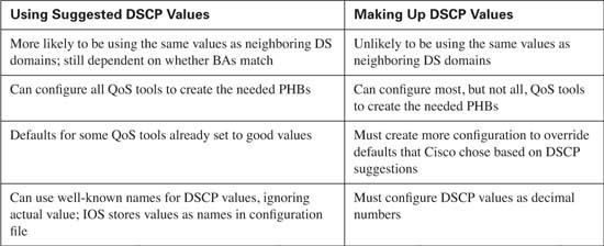
DiffServ suggests two other sets of PHBs and DSCP values besides the class selector values, namely assured forwarding (AF) and expedited forwarding (EF). Can you just decide to make up random 6-bit values to associate with each BA? Yes. Can you configure most QoS tools to give each BA the PHB that you desire? Sure. If you take the time to learn and follow DiffServ’s suggestions, such as CS, AF, and EF, however, then you can take advantage of some good defaults in IOS, increase the odds of compatibility between your DS domain and others, and avoid a lot of extra configuration.
Table 2-12 summarizes some of the key points about choosing to follow DiffServ’s suggestions.
The next two sections cover the DiffServ RFCs’ main suggestions for DSCP values to be assigned.
RFC 2597 defines something called “the assured forwarding per-hop behaviors.” This RFC suggests that one good DiffServ design choice would be to allow for four different classes for queuing purposes. Within each queue, three levels of drop probability could be implied. The RFC title rightfully suggests that the focus is on the QoS behavior—the PHB—at each node. Most engineers also think of the RFC as defining the 12 DSCPs that are used in conjunction with the AF PHBs.
An individual PHB describes what happen in a single hop, most typically a router. In the case of AF, each PHB contains two separate QoS function, typically performed by two different QoS tools. The first function is queuing. Each router classifies the packets into four different classes, and packets from each class are placed in a separate queue. AF does also specify that the queuing method support the ability to reserve a minimum configured bandwidth for each class.
The AF PHB defines Congestion Avoidance as the second behavior that comprises the AF PHB. Routers drop packets when a queue is full and the router needs to place the packet in the queue; this action is called tail drop. Congestion Avoidance tools discard packets before tail drop is required, hoping that fewer packets are dropped, as described earlier in this chapter. In Cisco routers, this part of the AF PHB is implemented using some form of RED.
The AF PHB does not define that it wants a guarantee that each packet will be delivered, nor does it imply any form of error recovery. The name assured forwarding sometimes evokes visions that the bandwidth throughout the network is guaranteed, but it is not. The real objective can be seen with a short read of RFC 2597, which reveals a view of an enterprise and an ISP. The ISP wants to assure the customer that his traffic will get through the network, so long as the customer does not send more data than is contracted. For instance, maybe the enterprise has three classes (BAs) of traffic, for which they contract 300 kbps for the first, 200 kbps for the second, and 100 kbps for the third. The ISP would like to assure that these levels are met. Because many queuing tools effectively guarantee bandwidth over time, the ISP can give these BAs the appropriate amount of bandwidth. Because packet arrival times and rates vary, however, the queues inside the ISP’s network will grow and shrink. Congestion will occur; the ISP knows it, and the enterprise customer knows it. So, when temporary congestion occurs in the ISP network, it would be nice to know which type of packets to throw away under limited congestion, and which type to throw away under moderate congestion, and which ones to throw away under heavy congestion. Letting the customer define which traffic is discarded most aggressively also lets the customer achieve some control of how its traffic is treated by the ISP. Therefore, assured forwarding does not mean that an individual packet is assured of making it across the network; it does mean that attempts will be made to assure that queuing tools provide enough bandwidth, and when congestion does occur, less important traffic will be discarded first.
RFC 2597, and the AF PHB concepts, can be summarized as follows:
![]() Use up to four different queues, one for each BA.
Use up to four different queues, one for each BA.
![]() Use three different congestion thresholds inside each queue to determine when to begin discarding different types of packets.
Use three different congestion thresholds inside each queue to determine when to begin discarding different types of packets.
![]() To mark these packets, 12 DSCP values are needed; the names of these values as start with “AF” (assured forwarding).
To mark these packets, 12 DSCP values are needed; the names of these values as start with “AF” (assured forwarding).
Note RFC 3260 clarifies some of the meaning and terminology used with DiffServ. Technically, the AF PHB, according to RFC 3260, is actually four different PHBs—one for each class. Frankly, for purposes of passing the Cisco QOS exam, I do not think that will ever matter; I only mention it here to be fully correct.
Table 2-13 lists the names of the DSCP values, the queuing classes, and the implied drop likelihood.

Pay particular attention to the explanation of Table 2-13 inside this paragraph, because the values in the chart can be counterintuitive. Unlike the CS PHB, AF does not follow the “bigger-is- better” logic for the AF DSCPs. First, AF11, AF12, and so on are names for DSCP values, not the binary of decimal equivalent. (Those values are listed momentarily.) Given the names, at least you can think of the first “digit” after the AF to be the queuing classification—for example, all AF4x code points are in the same class for queuing. No specific queuing parameters are implied for any of these classes, so there is no inherent advantage to being in class 4 versus class 1.
Similarly, the second numeric digit in the AF DSCP names imply the drop preference—with 3 meaning highest likelihood of being dropped, and 1 meaning the least likelihood. In other words, inside a single class, an AFx3 DSCP would mean that these packets would be dropped more quickly (more aggressively) than AFx2, which would be dropped more aggressively than AFx1 packets. In the actual DSCP names, a bigger number for the second numeric digit actually implies a less-desirable QoS behavior. (This convention is also true of the actual binary values.)
You can read about DiffServ AF PHBs, configure DiffServ-compliant IOS tools, and never really have to know the underlying binary values and their decimal equivalents. For reference, however, Table 2-14 includes them. As noted earlier, the numeric parts of the AF code points did not follow the same bigger-is-better scheme that IP precedence did in the past. Likewise, the actual underlying binary values do not follow a bigger-is-better scheme, either.

The binary DSCP values imply the queuing class with the first 3 bits (bits 0 through 2), and the drop preference in the next two bits (bits 3 and 4). Queuing tools that operate only on IP precedence can still react to the AF DSCP values, essentially making the AF DSCPs backward compatible with non-DiffServ nodes for queuing, at least. Note that the “bigger-is-not-always- better” attitude continues with the actual binary values—the smaller the value of bits 3 and 4, the lower the probability of being discarded.
Note To convert from the AF name to the decimal equivalent, you can use a simple formula. If you think of the AF values as AFxy, the formula is
8x + 2y = decimal value.
For example, AF41 gives you a formula of (8 * 4) + (2 * 1) = 34.
In summary, DiffServ AF PHB provides the following:
![]() An overriding goal to provide PHBs that provide enough bandwidth for each class, with the ability to drop less important traffic, hoping to avoid dropping more important traffic, if congestion does occur.
An overriding goal to provide PHBs that provide enough bandwidth for each class, with the ability to drop less important traffic, hoping to avoid dropping more important traffic, if congestion does occur.
![]() A convention that provides 4 classes for queuing.
A convention that provides 4 classes for queuing.
![]() The convention includes three drop preferences inside each class.
The convention includes three drop preferences inside each class.
![]() Twelve code point names and values to use to create the four classes with three drop levels each.
Twelve code point names and values to use to create the four classes with three drop levels each.
RFC 2598 defines the expedited forwarding per-hop behaviors. This RFC defines a very simple PHB (low latency, with a cap on bandwidth), and a single DSCP (EF) to represent it. Expedited forwarding simply states that a packet with the EF DSCP should minimize delay, jitter, and loss, up to a guaranteed bandwidth level for the class.
Like AF, the EF RFC suggests two QoS actions be performed to achieve the PHB. First, queuing must be used to minimize the time that EF packets spend in a queue. To reduce delay, the queuing tool should always service packets in this queue next. Anything that reduces delay reduces jitter. Always servicing the EF queue first greatly reduces the queue length, which in turn greatly reduces the chance of tail drop due to the queue being full. Therefore, EF’s goal of reducing delay, jitter, and loss can be achieved with a queuing method such as Priority Queuing, with EF traffic in the most important queue.
The second component of the EF PHB is policing. If the input load of EF packets exceeds a configured rate, the excess packets are discarded. If 100 kbps is reserved for the EF BA, and 200 kbps enters the network, for example, supporting the extra traffic may be unreasonable. Why not just accept the extra traffic? The queuing method used to achieve low delay, low jitter, and low loss, would prevent other types of traffic from getting any bandwidth, because the queuing method always gives preference to EF traffic. Thus, EF protects the other traffic by capping the amount of bandwidth for the class. In other words, EF suggests a great level of service, but just up to the contracted amount of bandwidth.
The expedited forwarding PHB uses a DSCP name of EF, whose binary value is 101110, with a decimal value of 46.
Table 2-15 summarizes many of the key points about the various DiffServ PHBs.

DiffServ provides a formalized but sensible approach to QoS over the Internet. By using classes that aggregate the packets of many flows, DiffServ can scale well in the Internet. The next section covers the other specification for an Internet QoS model: IntServ.
Integrated services (IntServ) defines a different model for QoS than does DiffServ. IntServ defines a signaling process by which an individual flow can request that the network reserve the bandwidth and delay needed for the flow. The original work grew out of the experiences of the IETF in multicasting the audio and video for IETF meetings in the early to mid-1990s.
To provide guarantees per flow, IntServ RFC 1633 describes two components: resource reservation and admission control. Resource reservation signals the network elements about how much bandwidth and delay a particular flow needs. If the signaling completes successfully, the various network components have reserved the needed bandwidth. The collective IntServ nodes (typically routers) reserve the appropriate amount of bandwidth and delay in response to the signaling messages.
IntServ admission control decides when a reservation request should be rejected. If all requests were accepted, eventually too much traffic would perhaps be introduced into the network, and none of the flows would get the requested service.
Figure 2-17 shows the general idea behind the IntServ reservation requests.
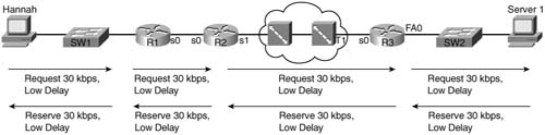
IntServ uses Resource Reservation Protocol (RSVP, RFCs 2205 through 2215) for signaling to reserve the bandwidth. With a full IntServ implementation (more on that later), the originator of the flow (Hannah) begins signaling. At each router along the route, the router asks itself, “Can I support this request?” If the answer is yes, it forwards the request to the next router. Each router holds the bandwidth temporarily, waiting on the confirmation to flow back to the originator (Hannah). When each router sees the reserve RSVP command flow back to the originator, each router completes the reservation.
What does it mean for the router to “reserve” something? In effect, the router reserves the correct queuing preferences for the flow, such that the appropriate amount of bandwidth is allocated to the flow by the queuing tool. RSVP can also request a certain (low) amount of delay, but implementing a guarantee for delay is a little more difficult; IOS, for instance, just reserves the queuing preference. In fact, IntServ RFCs actually define the term “guarantee” as a relatively loose goal, and it is up to the actual implementation to decide how rigorous or general to make the guarantees.
RSVP continues signaling for the entire duration of the flow. If the network changes, or links fail and routing convergence occurs, the network may no longer be able to support the reservation. Therefore, RSVP reserves the bandwidth when the flow initializes and continues to ensure that the flow can receive the necessary amount of bandwidth.
IntServ has some obvious disadvantages, and it has several advantages. IntServ actually predates DiffServ; DiffServ, to some degree, was developed to provide an Internet-scale QoS model, because IntServ scales poorly. IntServ expects the hosts to signal for service guarantees, which brings up two issues—whether the hosts can be trusted by the network and whether the hosts actually support RSVP. Alternatively, routers can be configured to reserve bandwidth on behalf of hosts, but the configuration can quickly become an administrative problem because additional configuration would need to be added for each reserved flow. Also IntServ works best when all intermediate networks support IntServ. Take a look at Figure 2-18, for example. Whereas McCoy, Hatfield, and ISP2 support IntServ, ISP1 does not.

IntServ, with RSVP signaling, can work in this network. However, for ISP1, one of two things must be done to support IntServ:
![]() ISP1 must pass the RSVP messages through; the ISP1 router just treats the traffic as best effort.
ISP1 must pass the RSVP messages through; the ISP1 router just treats the traffic as best effort.
![]() ISP1 passes the RSVP messages; RSVP flows are mapped to DiffServ classes inside the ISP1 DiffServ domain.
ISP1 passes the RSVP messages; RSVP flows are mapped to DiffServ classes inside the ISP1 DiffServ domain.
Another problem with IntServ in large networks and in the Internet relates to the fact the RSVP reserves bandwidth per flow. With DiffServ, for instance, all web traffic might be marked with DSCP AF21 and placed into a single class—even if there are hundreds, thousands, or tens of thousands of flows. With IntServ, each flow causes a separate reservation. In fact, DiffServ created an “Internet-scale” QoS model in part because the earlier IntServ specification did not scale well for the Internet, even if you could get most or all ISPs to implement IntServ and RSVP.
Are there advantages to IntServ? Of course. It can reserve specific amounts of bandwidth for a particular flow, which can be very useful. However, IntServ may never be pervasively deployed in an enterprise, or throughout the Internet. For instance, reserving bandwidth for flows between key video-conferencing stations may be useful. Allowing voice gateways to request reservations for VoIP calls can also help. The DiffServ model can be used to place all VoIP into a class, and give the class better treatment, but IntServ can guarantee the QoS behavior and reject new calls if the network is currently not ready to accept more traffic.
The QOS exams cover IntServ-related concepts and features, although DiffServ-related features certainly get much more coverage. The following list summarizes some of the key points about IntServ that you will want to remember for the QOS exams:
![]() Integrated services defines the need, and suggests mechanisms, to provide bandwidth and delay guarantees to flows that request it. RFC 1633 defines it.
Integrated services defines the need, and suggests mechanisms, to provide bandwidth and delay guarantees to flows that request it. RFC 1633 defines it.
![]() IntServ contains two components: resource reservation and admission control.
IntServ contains two components: resource reservation and admission control.
![]() RSVP, as defined in RFCs 2205 through 2215, provides the IntServ resource reservation function. RFC 2210 specifically discusses RSVP’s usage for IntServ.
RSVP, as defined in RFCs 2205 through 2215, provides the IntServ resource reservation function. RFC 2210 specifically discusses RSVP’s usage for IntServ.
![]() With end-to-end RSVP, each intermediate router reserves the needed bandwidth when receiving a reservation request and confirms the request with RSVP reserve messages. If a router in the path does not speak RSVP, it just transparently passes the flow.
With end-to-end RSVP, each intermediate router reserves the needed bandwidth when receiving a reservation request and confirms the request with RSVP reserve messages. If a router in the path does not speak RSVP, it just transparently passes the flow.
![]() When IntServ has not been implemented end to end, the RSVP messages can be forwarded in the non-IntServ part of the networks. In that case, the non-IntServ networks can either provide best-effort (BE) service, or provide IntServ-DSCP mapping if the intermediate network is a DiffServ domain.
When IntServ has not been implemented end to end, the RSVP messages can be forwarded in the non-IntServ part of the networks. In that case, the non-IntServ networks can either provide best-effort (BE) service, or provide IntServ-DSCP mapping if the intermediate network is a DiffServ domain.
![]() A router can offload the admission control function to a COPS server.
A router can offload the admission control function to a COPS server.
So far, you’ve read about the two actual QoS models, DiffServ and IntServ. Arguably, there is a third QoS model called Best Effort, which simply means that no QoS is applied to any of the traffic. Although that might seem to be a bad idea, remember that most Enterprise networks began using Best Effort, and the Internet was originally established as a Best Effort service, and it continues to be so today to a large degree. And by having more bandwidth available in the network than the network traffic requires, Best Effort can be a reasonable strategy in some networks.
Although all three QoS models are important, the QOS exam focuses on DiffServ. It is important, however, to note the advantages and disadvantages of all three QoS models, as listed in Table 2-16.

The “Foundation Summary” is a collection of tables and figures that provide a convenient review of many key concepts in this chapter. For those of you already comfortable with the topics in this chapter, this summary could help you recall a few details. For those of you who just read this chapter, this review should help solidify some key facts. For any of you doing your final prep before the exam, these tables and figures are a convenient way to review the day before the exam.
Table 2-17 lists the IOS classification and marking tools, along with a few key features that differentiate the tools.

Table 2-18 outlines the key features of IOS queuing methods.

Figure 2-19 depicts the typical points in a network where policing and shaping are typically deployed.

Table 2-19 outlines the key features of IOS policing and shaping tools.
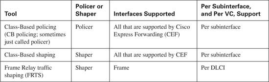
Table 2-20 lists the tools, and the various points for comparison, for Congestion Avoidance tools.

Table 2-21 lists the link-efficiency tools and some of the pertinent comparison points.
Table 2-21 Comparison of Link-Efficiency Tools

* The Frame Relay Forum is often referred to as FRF; their document names tend to begin with the letters FRF as well. The QoS feature called Frame Relay Fragmentation is also referred to as FRF.
Table 2-22 lists the RFCs that define DiffServ.
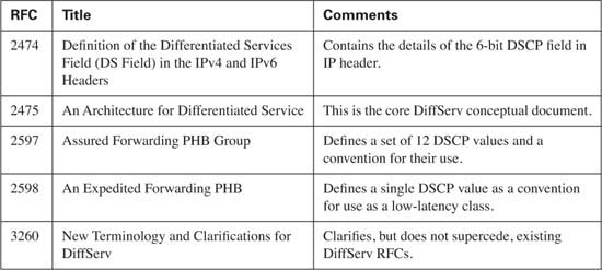
Figure 2-20 puts some of the DiffServ terminology in context.

Figure 2-21 shows two enterprise networks and two ISPs, with examples of several of the DiffServ terms relating to interconnecting networks.

Figure 2-22 shows the fields inside the ToS byte (per RFC 1349) and the DS field (per RFC 2474).
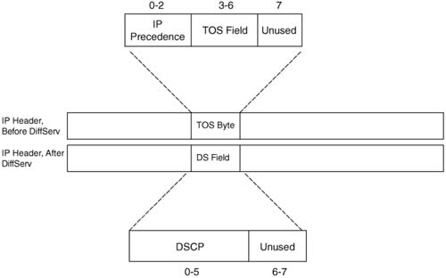
Table 2-23 lists DSCP values useful for QoS tools that only use precedence, and for those that also use DSCP.

The names of the code points in Table 2-14 match parameters found on IOS DiffServ-compliant classification commands. Because an “all-zeros” DSCP called “default” was already defined, there was no need to create a CS0 DSCP name.
Table 2-24 lists the DiffServ AF DSCPs.
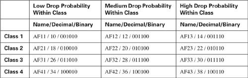
Table 2-25 summarizes many of the key points about the various DiffServ PHBs.

As mentioned in the Introduction, you have two choices for review questions. The questions that follow next give you a more difficult challenge than the exam itself by using an open-ended question format. By reviewing now with this more difficult question format, you can exercise your memory better, and prove your conceptual and factual knowledge of this chapter. You can find the answers to these questions in Appendix A.
The second option for practice questions is to use the CD-ROM included with this book. It includes a testing engine and more than 200 multiple-choice questions. You should use this CD-ROM nearer to the end of your preparation, for practice with the actual exam format. You can even customize the CD-ROM exam to include, or not include, the topics that are only on the CCIP QoS.
|
1. |
List the two classification and marking tools mentioned in this chapter, including the full names and popular acronyms. |
|
2. |
List four queuing tools, including the full names and popular acronyms. |
|
3. |
List the two shaping tools mentioned in this chapter, including the full names and popular acronyms. |
|
4. |
List three Congestion Avoidance tools, including the full names and popular acronyms. |
|
5. |
List four link efficiency tools, including the full names and popular acronyms. |
|
6. |
List the QoS tools that perform some classification function. |
|
7. |
Which of the following tools can be used for classification and marking? CB marking, PQ, CB shaping, WFQ, WRED, FRTS, LLQ, MLPPP LFI, NBAR, QPM, cRTP |
|
8. |
Which of the following tools can be used for queuing? CB marking, PQ, CB shaping, WFQ, WRED, FRTS, LLQ, MLPPP LFI, NBAR, QPM, cRTP |
|
9. |
Which of the following tools can be used for shaping? CB marking, PQ, CB shaping, WFQ, WRED, FRTS, LLQ, MLPPP LFI, NBAR, QPM, cRTP |
|
10. |
Which of the following tools can be used for link efficiency? CB marking, PQ, CB shaping, WFQ, WRED, FRTS, LLQ, MLPPP LFI, NBAR, QPM, cRTP |
|
11. |
Define the DiffServ term “behavior aggregate.” |
|
12. |
Define the DiffServ term “DSCP,” including what the acronym stands for. |
|
13. |
Define the DiffServ term “PHB,” including what the acronym stands for. |
|
14. |
Define the DiffServ term “MF classifier,” including what the acronym stands for. |
|
15. |
Define the DiffServ term “DS ingress node,” including what the acronym stands for. |
|
16. |
Compare and contrast the terms “BA classifier” and “MF classifier,” according to DiffServ specifications. Suggest typical points in the network where each is used. |
|
17. |
Compare and contrast the contents of the IP ToS byte before and after the advent of DiffServ. |
|
18. |
Describe the QoS behavior at a single DS node when using the AF PHB. Also explain what the acronym “AF PHB” represents and identify the RFC that defines it. |
|
19. |
Explain (by comparing and contrasting) whether AF and CS PHB DSCPs conform to the concept that “bigger DSCP values are better than smaller values.” |
|
20. |
Describe the QoS behavior at a single DS node when using the EF PHB. Also explain what the acronym “EF PHB” represents and identify the RFC that defines it. |
|
21. |
Describe the process used by RSVP to reserve bandwidth in a network. |
|
22. |
Compare and contrast DiffServ and IntServ in terms of using classes, flows, and scalability. |
|
23. |
List and describe the two key advantages of the Best Effort model for QoS. |
|
24. |
List and describe the two key advantages of the DiffServ model for QoS. |
|
25. |
List and describe the two key disadvantages of the DiffServ model for QoS. |
|
26. |
List and describe the two key disadvantages of the IntServ model for QoS. |