Chapter 10. Cisco QoS Best Practices
QOS Exam Topics
This chapter covers the following exam topics specific to the QoS exam:
![]() Explain the QoS requirements of the different application types
Explain the QoS requirements of the different application types
![]() List typical enterprise traffic classes; then, identify the delay, jitter, packet-loss, and bandwidth requirements of each traffic class
List typical enterprise traffic classes; then, identify the delay, jitter, packet-loss, and bandwidth requirements of each traffic class
![]() Explain the best practice QoS implementations and configurations within the campus LAN
Explain the best practice QoS implementations and configurations within the campus LAN
![]() Explain the best practice QoS implementations and configurations on the WAN customer edge (CE) and provider edge (PE) routers
Explain the best practice QoS implementations and configurations on the WAN customer edge (CE) and provider edge (PE) routers
Today’s applications require converged networks to provide predictable, measurable, and possibly guaranteed service to facilitate the productivity of your end users. As network applications grow in number and complexity, this simple truth becomes more and more apparent. The days of classifying all traffic into a single class that receives best-effort treatment is rapidly becoming a methodology of the past.
The previous nine chapters of this book describe in detail the various concepts and methods available to you for the configuration of classification, congestion management, and congestion avoidance on Cisco routers and switches. This chapter is designed to pull these concepts together, illustrating the Cisco best practices for a converged network.
The purpose of the “Do I Know This Already?” quiz is to help you decide whether you need to read the entire chapter. If you already intend to read the entire chapter, you do not necessarily need to answer these questions now.
The 15-question quiz, derived from the major sections in the “Foundation Topics” portion of the chapter, helps you determine how to spend your limited study time.
Table 10-1 outlines the major topics discussed in this chapter and the “Do I Know This Already?” quiz questions that correspond to those topics.
Caution The goal of self-assessment is to gauge your mastery of the topics in this chapter. If you do not know the answer to a question or are only partially sure of the answer, mark this question wrong for purposes of the self-assessment. Giving yourself credit for an answer you correctly guess skews your self-assessment results and might provide you with a false sense of security.
You can find the answers to the “Do I Know This Already?” quiz in Appendix A, “Answers to the ‘Do I Know This Already?’ Quizzes and Q&A Sections.” The suggested choices for your next step are as follows:
![]() 8 or less overall score— Read the entire chapter. This includes the “Foundation Topics,” the “Foundation Summary,” and the “Q&A” sections.
8 or less overall score— Read the entire chapter. This includes the “Foundation Topics,” the “Foundation Summary,” and the “Q&A” sections.
![]() 9 or 10 overall score— If you want more review on these topics, skip to the “Foundation Summary” section and then go to the “Q&A” section. Otherwise, move to the next chapter.
9 or 10 overall score— If you want more review on these topics, skip to the “Foundation Summary” section and then go to the “Q&A” section. Otherwise, move to the next chapter.
|
1. |
Which of the following traffic types provides a consistent packet exchange? a. Interactive video b. Voice media c. Voice signaling d. Mission-critical data |
|
2. |
Which of the following factors influence the bandwidth requirements of a VoIP call? a. Layer 3 routing protocol b. Layer 2 media type c. Codec selection d. Speech samples per packet |
|
3. |
The International Telecommunications Union (ITU) G.114 specification states that the one-way delay of a voice packet should not exceed how many milliseconds (ms)? a. 100 b. 150 c. 200 d. 250 |
|
4. |
How much bandwidth should be provisioned for a 384-kbps interactive video stream? a. 384 kbps—The average rate of the stream b. 460.8 kbps—The average rate of the stream + 20% c. 768 kbps—The average rate of the stream * 2 d. 192 kbps—The size of H.264 compressed video |
|
5. |
How sensitive is mission-critical data to jitter? (Link: Data Traffic) a. Low b. Low to moderate c. Moderate to high d. High |
|
6. |
A converged network should be designed for less than what percentage of packet loss in the class that supports real-time applications? a. .5 b. 1 c. 1.5 d. 5 |
|
7. |
A converged network should be designed for less than how many milliseconds of jitter in the class that supports real-time applications? a. 10 b. 20 c. 30 d. 40 |
|
8. |
Where should traffic be classified? a. In the core b. As close to the source as possible c. As close to the destination as possible d. On the WAN router |
|
9. |
What is the recommended differentiated services code point (DSCP) value for scavenger traffic? a. 0 b. CS0 c. CS1 d. AF13 |
|
10. |
What is the recommended DSCP class for bulk data applications? a. AF1x b. AF2x c. AF3x d. EF |
|
11. |
What are the preferred methods of queuing on Cisco routers? a. PQ and CBWFQ b. PQ and CQ c. LLQ and CBWFQ d. LLQ and CQ |
|
12. |
When using LFI, what is the recommended serialization delay of a voice packet? a. 5–10 ms b. 10–15 ms c. 15–20 ms d. 20–25 ms |
|
13. |
Where does WRED perform the most effectively? a. When applied to the LLQ b. When applied to a CBWFQ that services UDP applications c. When applied to a CBWFQ that services TCP applications d. When applied to a CBWFQ that services both UDP and TCP applications |
|
14. |
What QoS mechanism should never be used in the core of the campus LAN? a. Classification and marking b. Congestion management c. Congestion avoidance |
|
15. |
If the service provider manages the CE router, what inbound policy is required on the PE router? a. Classification and marking b. Congestion management c. Policing d. All of the above e. None of the above |
This chapter describes the Cisco QoS best practices for the implementation of QoS across a converged network by discussing the following topics:
![]() The need for QoS best practices
The need for QoS best practices
![]() End-to-end QoS
End-to-end QoS
![]() QoS service level agreements (SLAs)
QoS service level agreements (SLAs)
![]() Application requirements for QoS
Application requirements for QoS
![]() QoS best practices methodology
QoS best practices methodology
![]() QoS best practices case studies
QoS best practices case studies
Imagine a world without standards or accepted conventions. Driving down the highway, you notice that the information on each sign is written in a different language. The information you need to know is there, but is represented in a manner you are not familiar with. How do you make sense of this information? Deciding to take the next exit to pull off the highway and get your bearings, you drive up the exit ramp only to discover the cars on this road are driving on the opposite side of the street. How can you predict which side to drive on if each road has its own conventions? Awkwardly, you merge into the traffic and begin to travel on what feels like the wrong side of the road. Looking up, you see a traffic light in front of you that changes colors from blue to orange. What do you do? This is not a normal convention that you are accustomed to. Does orange mean stop, go, or caution? Although this mixed-up world can function, simple tasks become complex and fraught with hazards. To function efficiently and effectively, standards need to be agreed upon and instituted throughout the highway infrastructure.
QoS configuration of your network parallels this example. With so many QoS configuration options available, it is sometimes difficult to decide which method is best for your network. Common questions include the following:
![]() What is the best way to identify and classify my traffic?
What is the best way to identify and classify my traffic?
![]() At what point in my network should I classify my traffic?
At what point in my network should I classify my traffic?
![]() At what point in my network do I trust the markings that I receive?
At what point in my network do I trust the markings that I receive?
![]() What is the best way to ensure that my real-time applications always receive priority treatment without starving other mission-critical applications?
What is the best way to ensure that my real-time applications always receive priority treatment without starving other mission-critical applications?
![]() How do I limit unwanted or unnecessary traffic throughout my network?
How do I limit unwanted or unnecessary traffic throughout my network?
The goal of the Cisco QoS best practices methodology is to answer these questions and offer a standardized methodology that can be used throughout your network.
End-to-end QoS is a term that describes the treatment a packet receives at every node as it travels across your network from the originating device to the terminating device. The Internet Engineering Task Force (IETF) has defined two models to accomplish this goal:
![]() Integrated Services (IntServ)—Requires that each node establish a guaranteed bandwidth, delay, and jitter before a single packet is sent
Integrated Services (IntServ)—Requires that each node establish a guaranteed bandwidth, delay, and jitter before a single packet is sent
![]() Differentiated Services (DiffServ)—Requires that each node be configured to classify and schedule each packet as it is received on a per-hop basis
Differentiated Services (DiffServ)—Requires that each node be configured to classify and schedule each packet as it is received on a per-hop basis
This chapter describes end-to-end QoS based upon the DiffServ model.
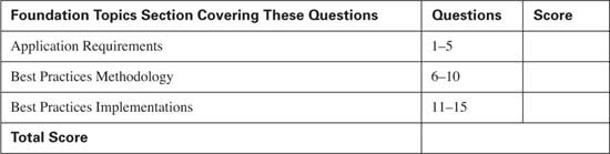
Consider the typical converged network depicted in Figure 10-1.
A packet leaves the Remote IP Phone at the enterprise remote site bound for its destination, HQ IP Phone at the enterprise HQ site. During the journey, the packet traverses switch SW1, Router R1, Router SP1, Router SP2, Router SP4, Router R2, and finally switch SW2. Each node along this path must have the capability to offer the same treatment, or class of service (CoS), to the packet. If any node along this path cannot offer the necessary CoS for this traffic, the end-to-end QoS of the network can be compromised, possibly resulting in an unintelligible conversation. End-to-end QoS is only as strong as the weakest node.
Achieving end-to-end QoS consists of identifying traffic flows and classifying them into groups that each node can recognize and act upon. This requires that an agreed-upon standard for classification and prioritization be in place for each node the packet traverses. This agreed-upon standard, or best practice, determines the action taken for each packet on its journey from originating source to final destination.
In the network in Figure 10-1, the network administrator has the ability to configure Routers R1 and R2 and Switches SW1 and SW2 to provide the CoS desired for each type of traffic on the network. However, the network administrator does not have direct control over the service provider’s Routers SP1, SP2, SP3, and SP4. To maintain the desired classification and prioritization of the traffic over the service provider’s network, there must be an agreement between the enterprise and the service provider to accomplish this. This agreement is called a service level agreement (SLA). An SLA is a contractual agreement that stipulates how each defined class of traffic will be treated and any penalties involved if this agreement is not met. The treatment may consist of bandwidth, delay, jitter, and high-availability guarantees, depending upon the level of service that is purchased.
In the past, service provider networks typically offered only bandwidth guarantees for data networks, without regard for other metrics such as delay and jitter. In a data network without real-time applications, this was an acceptable solution. If a TCP packet was delayed, experienced jitter, or was lost, the application would recover without affecting the productivity of the end users. In today’s networks that transport real-time applications, delay, jitter, and packet loss are much more of a concern.
To address this concern, service providers are differentiating themselves by offering an SLA to guarantee delay, jitter, packet loss, and bandwidth rates to give their enterprise customers the ability to transport real-time applications end-to-end without degradation.
An SLA can be offered on a per interface basis, if the physical link is dedicated to a single customer, or on a per permanent virtual circuit (PVC) basis, if multiple customers share the physical link. A typical SLA offers the capability to classify and prioritize three to five classes of traffic. The class that services real-time applications typically receives a maximum-bandwidth guarantee, a delay guarantee, a jitter guarantee, and a packet-loss guarantee. The remaining classes typically transport data applications and offer a minimum-bandwidth (best-effort) guarantee. Depending on the needs of the data traffic, delay, jitter, and packet-loss guarantees can be purchased for these classes as well.
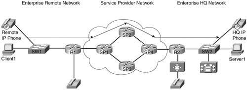
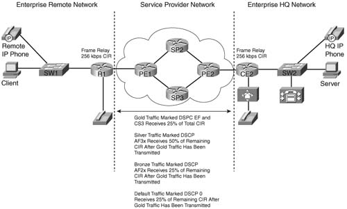
Consider the SLA offered by the service provider in Figure 10-2.
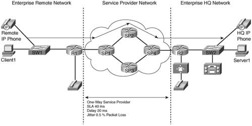
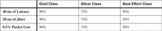
In this network, assume that the service provider offers an SLA of 40 ms of latency, 20 ms of jitter, and 0.5 percent packet loss for three classes of service:
![]() Gold—Gold traffic consists of real-time applications. Traffic within this class is guaranteed a maximum amount of bandwidth and guaranteed this level of service 90 percent of the time for traffic that does not exceed the maximum bandwidth. Traffic that exceeds the guaranteed maximum bandwidth will be reclassified as best-effort traffic.
Gold—Gold traffic consists of real-time applications. Traffic within this class is guaranteed a maximum amount of bandwidth and guaranteed this level of service 90 percent of the time for traffic that does not exceed the maximum bandwidth. Traffic that exceeds the guaranteed maximum bandwidth will be reclassified as best-effort traffic.
![]() Silver—Silver traffic consists of premium data applications. Traffic within this class is guaranteed a minimum amount of bandwidth and guaranteed this level of service 75 percent of the time for traffic that does not exceed the minimum bandwidth. Traffic that exceeds the guaranteed minimum bandwidth will be reclassified as best-effort traffic.
Silver—Silver traffic consists of premium data applications. Traffic within this class is guaranteed a minimum amount of bandwidth and guaranteed this level of service 75 percent of the time for traffic that does not exceed the minimum bandwidth. Traffic that exceeds the guaranteed minimum bandwidth will be reclassified as best-effort traffic.
![]() Best-effort—Best-effort traffic consists of all traffic that has been reclassified and any other unclassified application traffic. Traffic within this class is guaranteed a minimum amount of bandwidth and guaranteed this level of service 50 percent of the time. Traffic that exceeds the guaranteed minimum bandwidth will be sent if bandwidth is available. If no bandwidth is available, this traffic will be dropped.
Best-effort—Best-effort traffic consists of all traffic that has been reclassified and any other unclassified application traffic. Traffic within this class is guaranteed a minimum amount of bandwidth and guaranteed this level of service 50 percent of the time. Traffic that exceeds the guaranteed minimum bandwidth will be sent if bandwidth is available. If no bandwidth is available, this traffic will be dropped.
Table 10-2 lists the SLA values used in this example.
With the SLA in place, the administrator of the enterprise network can plan for the implementation of end-to-end QoS and develop a QoS strategy for Routers R1 and R2 and Switches SW1 and SW2 to meet the needs of the enterprise applications.
Many service provides also offer the option of managing the customer’s WAN edge router. In Figure 10-2, assume that the service provider manages Routers R1 and R2. In this case, Routers R1 and R2 would be configured and maintained by the service provider. The SLA offered by the service provider could then be extended to include the managed routers at the customer’s premise. An additional class of traffic can then be defined to allow the prioritization of management traffic, such as Telnet and Simple Network Management Protocol (SNMP), to ensure that the service provider can access the routers during times of heavy congestion.
The traffic flow generated by an application dictates the QoS needs for that application. Some applications generate a consistent traffic flow, consuming the same amount of bandwidth throughout the packet exchange, whereas other applications vary greatly throughout the packet exchange. Understanding how your applications behave on your network is important in order to plan for the proper QoS treatment of each application. This section discusses the traffic behavior of consistent and inconsistent real-time applications as well as data traffic.
Voice traffic is extremely consistent. After a voice conversation has been established, the bandwidth requirements remain the same for the life of the conversation.
To fully understand the QoS requirements for the Cisco implementation of voice traffic, you must first understand how voice traffic is transported across the network. A single voice packet consists of the voice payload, a Real-Time Transport Protocol (RTP) header, a User Datagram Protocol (UDP) header, an IP header, and a Layer 2 header, as shown in Figure 10-3.
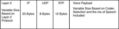
IP headers (20 bytes), UDP headers (8 bytes), and RTP headers (12 bytes), without the use of compressed RTP, consistently use 40 bytes per packet.
The voice payload is dependant upon the codec selected and the amount of speech included, measured in milliseconds. In Cisco IP Telephony environments, the two most common codec specifications are as follows:
![]() G.711—Carries an uncompressed 64-kbps payload stream, known in the traditional telephony world as pulse code modulation (PCM). G.711 offers toll-quality voice conversations at the cost of bandwidth consumption. The G.711 codec is ideally suited for situations where bandwidth is abundant and quality is the primary driver, such as LAN environments.
G.711—Carries an uncompressed 64-kbps payload stream, known in the traditional telephony world as pulse code modulation (PCM). G.711 offers toll-quality voice conversations at the cost of bandwidth consumption. The G.711 codec is ideally suited for situations where bandwidth is abundant and quality is the primary driver, such as LAN environments.
![]() G.729—Carries a compressed 8-kbps payload stream, known in the traditional telephony world as Conjugate Structure Algebraic Code-Excited Linear Prediction (CS-ACELP). G.729 offers a reduction in bandwidth consumption at the cost of near toll-quality voice conversations. G.729 is ideally suited for situations where bandwidth is limited, such as WAN environments.
G.729—Carries a compressed 8-kbps payload stream, known in the traditional telephony world as Conjugate Structure Algebraic Code-Excited Linear Prediction (CS-ACELP). G.729 offers a reduction in bandwidth consumption at the cost of near toll-quality voice conversations. G.729 is ideally suited for situations where bandwidth is limited, such as WAN environments.
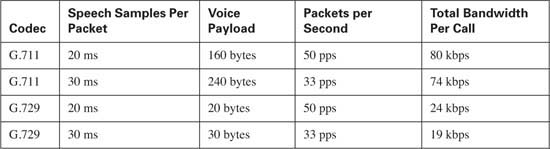
By default, the Cisco IP Telephony solutions place 20 ms of speech into a single G.711 or G.729 packet. This means that it takes 50 packets to generate a full second of the voice conversation, because
![]()
If the G.711 codec is selected using 50 packets per second (pps), the voice payload per packet will be 1280 bits, because
![]()
Expressed in bytes, this becomes 160 bytes because
![]()
If the G.729 codec is selected using 50 pps, the voice payload per packet will be 160 bits because
![]()
Expressed in bytes, this becomes 20 bytes because
![]()
Discounting the Layer 2 headers and compressed RTP
![]()
At 50 pps, this yields 10,000 bytes per voice stream or 80 kilobits per voice stream (10,000 * 8 = 80,000).
Discounting the Layer 2 headers and compressed RTP
![]()
At 50 pps, this yields 3000 bytes per voice stream or 24 kilobits per voice stream (3000 × 8 = 24,000).
Increasing the amount of speech included in a single packet from 20 ms to 30 ms decreases the number of packets required to transport that same second of voice. In this case, approximately 33 packets are needed (33 * 30 ms is approximately = to 1 second).
The voice payload of a G.711 packet @ 33 pps contains approximately 1939 bits (64,000 ÷ 33) or approximately 240 bytes (1939 ÷ 8). Adding the IP/UDS/RTP headers, this becomes 280 bytes (240 + 40) per packet. At 33 pps, this yields 9240 bytes per voice stream or approximately 74 kilobits.
The voice payload of a G.729 packet @ 33 pps contains approximately 242 bits (8000 ÷ 33) or approximately 30 bytes. Adding the IP/UDS/RTP headers, this becomes 70 bytes (30 + 40) per packet. At 33 pps, this yields 2310 bytes per voice stream or approximately 19 kilobits.
Table 10-3 lists these common G.711 and G.729 rates.
RTP Header Compression, also known as Compressed RTP (cRTP), voice activation detection (VAD), and Layer 2 headers also play a role in determining the bandwidth requirements of a voice conversation.
Header compression can be used to reduce the UDP/RTP header size on a per link basis. Typically, cRTP is used on slow-speed links to minimize the bandwidth requirements per voice conversation and to maximize the number of voice conversations that can be transported by reducing the UDP/ RTP header from 20 bytes to 2–4 bytes. Although cRTP can offer significant bandwidth savings, the impact on the router’s CPU performance increases for every voice conversation transported. Understand this impact on your hardware before enabling cRTP. For the purpose of bandwidth engineering in this section, cRTP will not be discussed.
Although VAD can be used to reduce the payload by transmitting 2 bytes of payload during silent times instead of the full payload size, for the purposes of bandwidth engineering, VAD should not be taken into account.
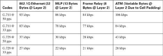
Layer 2 headers also play a role in determining the bandwidth requirements of voice conversations. Assume that a G.729 codec is used @ 50 pps, requiring 24 kbps per conversation and this conversation is carried over a Frame Relay circuit. The Frame Relay headers (8 bytes) need to be added to the required overhead for each frame. As discussed, each G.729 packet @ 50 pps consists of 60 bytes per packet. Adding the Frame Relay header brings the required bandwidth per frame to 68 bytes, or 544 bits per frame. At 50 pps, this yields 3400 bytes per voice stream or approximately 28 kilobits per voice stream.
Table 10-4 lists the common Layer 2 requirements and the total bandwidth required.
So far, this section has discussed the bandwidth required by voice media streams. To establish the media stream, you must first establish the properties of the stream. Referred to as call signaling, the list that follows presents just some of the included properties:
![]() Dialed number
Dialed number
![]() Calling number
Calling number
![]() Codec desired
Codec desired
Call signaling requires 150 bps plus the Layer 2 headers needed to transport the call signaling traffic across the network.
Bandwidth is only one of the QoS requirements needed to successfully transport voice across your network. Voice packets that are lost or delayed can lead to clipping, or missing parts of speech, in the voice conversation. The industry-standard algorithm used in Cisco digital signal processors (DSPs) has the capability to predict 30 ms of speech based upon previously received voice packets. This means that a single packet can be lost without the parties on the conversation noticing the loss. However, if more than one packet is lost in succession, the DSP cannot compensate and a clip will be heard in the conversation. Your network should be designed to limit packet loss of voice packets to less than 1 percent.
The International Telecommunications Union (ITU) G.114 specification states that the one-way delay of a voice packet from the source (the speaker’s mouth) to the destination (the listener’s ear) should not exceed 150 ms. Delays exceeding 200 ms can result in voice degradation.
Jitter is defined as the variation in delay. For example, if the first ten packets in a voice conversation arrive 20 ms apart and the eleventh packet arrives 30 ms after the tenth packet, the jitter of the eleventh packet is 10 ms. By default, Cisco IP Phones have an adaptive internal jitter buffer that buffer received voice packets and play the voice stream to the listener consistently, removing the small amount of received jitter. However, this adaptive jitter buffer can compensate for only 20–50 ms of received jitter. A packet received that has jitter greater than 50 ms will be discarded. Your network should be designed to limit jitter to 30 ms or less.
Table 10-5 lists the delay, jitter, and packet-loss requirements for transporting voice traffic.
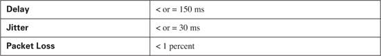
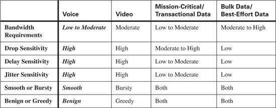
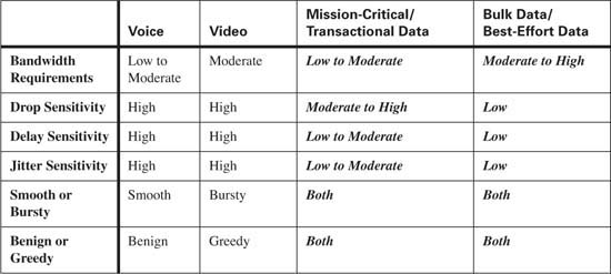
Although voice traffic is very consistent, it is intolerant of delay and network congestion. To minimize the effects of delay, jitter, and packet loss, voice traffic should always be placed in the priority queue, using Low Latency Queuing (LLQ) whenever possible. Table 10-6 compares the QoS requirements of voice traffic with other types of traffic.
Video traffic is fairly consistent, but does have the capability to burst. After a video stream has been established, the bandwidth requirements will fluctuate slightly during the life of the connection. A video stream begins by sending the entire picture being transmitted. After the picture has been established, the video stream sends only changes to the picture. If there is little movement in the displayed picture, few frames are sent, reducing the needed bandwidth. As movement increases, more frames need to be sent to compensate for this movement, increasing the required bandwidth.
Assume that you are participating in a videoconference and the average of the video stream is 384 kbps. During times of minimal movement, the transmit rate can drop significantly lower than 384 kbps; however, as you move around the camera, the transit rate begins to increase above 384 kbps. To compensate for these fluctuations in bandwidth requirements, video traffic should be provisioned by adding 20 percent to the average requirements. For example, the 384-kbps stream should be provisioned for 460.8 kbps, because 20 percent of 384 kbps is 76.8 kbps.
Interactive video traffic shares the same requirements for delay, jitter, and packet loss as voice traffic. Video packets that are lost or suffer too much delay or jitter can result in a lost picture or jerky video.
Table 10-7 lists the delay, jitter, and packet-loss requirements for transporting video traffic.
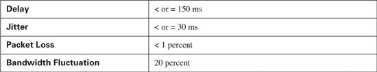
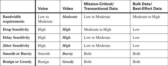
Although video traffic is fairly consistent it is intolerant of delay and network congestion. To minimize the effects of delay, jitter, and packet loss, video traffic should always be placed in the priority queue, using LLQ whenever possible. Table 10-8 compares the QoS requirements of video traffic with other types of traffic.
The QoS requirements of data applications vary based upon the needs of the particular application. Best practice is to have a baseline of each application on your network to determine the QoS requirements for your applications.
Data applications should be separated into no more than four or five distinct classes, with each class consisting of data applications that share the same QoS requirements. Typically, these classes consist of the following:
![]() Mission-critical applications—Mission-critical applications are defined as the core applications that your business relies upon to function effectively and efficiently. These applications are greedy and use as much bandwidth as they can. Because they are usually TCP-based, these applications are not sensitive to delay, jitter, and loss. These applications, which should be limited to three or less, will receive at least 50 percent of the bandwidth remaining after LLQ has serviced the priority traffic.
Mission-critical applications—Mission-critical applications are defined as the core applications that your business relies upon to function effectively and efficiently. These applications are greedy and use as much bandwidth as they can. Because they are usually TCP-based, these applications are not sensitive to delay, jitter, and loss. These applications, which should be limited to three or less, will receive at least 50 percent of the bandwidth remaining after LLQ has serviced the priority traffic.
![]() Transactional applications—Transactional applications are typically client/server applications that support your core business. Unlike mission-critical applications that can be greedy, transactional applications typically exchange small packets when adding, updating, deleting, or retrieving text data from a central point. However, these applications are usually sensitive to delay and packet loss. Transactional applications include Enterprise Resource Planning (ERP) applications such as SAP or Oracle. These applications, which should be limited to three or less, will receive at least 20 percent of the bandwidth remaining after LLQ has serviced the priority traffic.
Transactional applications—Transactional applications are typically client/server applications that support your core business. Unlike mission-critical applications that can be greedy, transactional applications typically exchange small packets when adding, updating, deleting, or retrieving text data from a central point. However, these applications are usually sensitive to delay and packet loss. Transactional applications include Enterprise Resource Planning (ERP) applications such as SAP or Oracle. These applications, which should be limited to three or less, will receive at least 20 percent of the bandwidth remaining after LLQ has serviced the priority traffic.
![]() Best Effort applications—Most applications use the best-effort class. These applications typically include e-mail, HTTP, and FTP traffic. The best-effort class will receive at least 25 percent of the bandwidth remaining after LLQ has serviced the priority traffic.
Best Effort applications—Most applications use the best-effort class. These applications typically include e-mail, HTTP, and FTP traffic. The best-effort class will receive at least 25 percent of the bandwidth remaining after LLQ has serviced the priority traffic.
![]() Scavenger (less than best-effort) applications—Using a scavenger class allows you to identify and limit bandwidth to less-desirable traffic. This type of traffic typically consists of applications such as the peer-to-peer file-sharing program Kazaa. These applications should receive no more than 5 percent of the bandwidth remaining after LLQ has serviced the priority traffic.
Scavenger (less than best-effort) applications—Using a scavenger class allows you to identify and limit bandwidth to less-desirable traffic. This type of traffic typically consists of applications such as the peer-to-peer file-sharing program Kazaa. These applications should receive no more than 5 percent of the bandwidth remaining after LLQ has serviced the priority traffic.
Because data applications are typically tolerant of delay, jitter, and packet loss, each class of data traffic will be provisioned using Class-Based Weighted Fair Queuing (CBWFQ). Using CBWFQ guarantees that a percentage of bandwidth will be available for each class.
By limiting the data classes to four or five classes, you have the ability to offer a more-defined level of service between the classes. Defining too many classes or defining too many applications within a class nullifies the benefits of QoS. For example, if all data traffic uses the mission-critical class, you lose the ability to differentiate the traffic and provide the desired level of service—in effect, nullifying QoS.
After you have a baseline of the applications in your network and determine the classes needed to provide the desired level of service, it is important to group applications with common requirements into the same class. For example, an FTP application and a transactional application should never be placed into the same class. The FTP stream is bursty and greedy, taking as much bandwidth as it can. This might delay the time-sensitive transactional application, causing the session to time out. Placing these applications into separate classes allows each to operate without impacting the other.
Data traffic is extremely variable depending upon the data application. Table 10-9 compares the QoS requirements of mission-critical/transactional traffic and best-effort traffic with other types of traffic.
So far, the chapters in this book discuss the various ways that QoS can be applied to a Cisco infrastructure and the QoS requirements for different types of traffic. This section discusses the Cisco best practices methodology for classification, congestion management, congestion avoidance, and policing using a Cisco infrastructure.
Note AutoQos VoIP chooses and configures automatically what it thinks are the appropriate QoS configuration settings. In some regards, those choices can be thought of as a set of best practices for VoIP traffic. Refer to Chapter 3, “MQC, QPM, and AutoQoS,” and particularly Tables 3-5, 3-6, and 3-8, for a brief review of QoS options with AutoQos VoIP, both on routers and switches.
Put simply, classification is nothing more than identifying a flow of traffic and grouping into common groups the traffic flows that share QoS requirements. Marking is a means to place a mark in each packet of the identified traffic flow for later nodes to identify.
Classification is performed at the trust boundary, which should be as close to the source as possible. In an enterprise environment, the trust boundary is typically implemented at the access layer switches or distribution layer switches. In a service provider’s network, the trust boundary is typically implemented at the CE or PE router. Performing classification as close to the source as possible simplifies the QoS configuration required by later nodes, because the downstream node will need to perform only congestion management and congestion avoidance.
Most Cisco routers and many Cisco switches offer the capability to identify and classify traffic through the use of the Network Based Application Recognition (NBAR) protocol. This capability greatly reduces the complexity of classifying traffic by automatically identifying the most common types of traffic found on today’s networks. Some trusted devices, such as Cisco IP Phones, have the capability to mark packets for classification. Alternatively, you can use an access list to classify a traffic flow based upon Layer 2 through 7 markings.
After you determine the method of classification, you can group the traffic into classes with other traffic that shares the same QoS requirements.
Assume that your network consists of IP telephony traffic, interactive video traffic, streaming video traffic, IP routing protocols, network management applications, and various data applications. Using a combination of NBAR, trust of IP phones, and access lists, each traffic flow can be placed into the appropriate group.
A single class will be created for voice media traffic. This class will consist of voice media traffic only. Each packet in the stream will be marked using a DSCP value of EF and a CoS value of 5.
A second class will be created for interactive video. This class will consist of interactive video traffic only. Each packet in the stream will be marked using a DSCP value of AF41 and a CoS value of 4.
A third class will be created for streaming video. This class will consist of streaming video traffic only. Each packet in the stream will be marked using a DSCP value of CS4 and a CoS value of 4.
A fourth class will be created for routing protocols. This class will consist of routing update traffic only. Each packet in the stream will be marked using a DSCP value of CS6 and a CoS value of 6.
A fifth class will be created for network management. This class will consist of network management traffic only. Each packet in the stream will be marked using a DSCP value of CS2 and a CoS value of 2.
No more than five distinct data classes should be used. These classes include the following:
![]() Mission-critical—Using DSCP AF3x and CoS of 3
Mission-critical—Using DSCP AF3x and CoS of 3
![]() Transactional—Using DSCP AF2x and CoS 2
Transactional—Using DSCP AF2x and CoS 2
![]() Bulk transfers—Using DSCP AF1x and CoS 1
Bulk transfers—Using DSCP AF1x and CoS 1
![]() Best Effort—Using DSCP 0 and CoS 0
Best Effort—Using DSCP 0 and CoS 0
![]() Scavenger traffic—Using DSCP CS1 and CoS 1
Scavenger traffic—Using DSCP CS1 and CoS 1
At this point, all traffic in the example network has been classified into the proper group. Each network has its own distinct application requirements and traffic patterns. Your network might or might not require each class of traffic used in the example network. If your network does not have each class of traffic that is discussed, it is a good practice to plan a seamless implementation strategy in case you add these classes in the future.
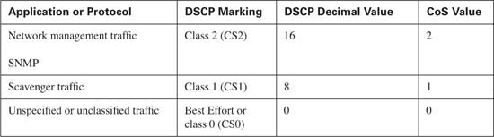
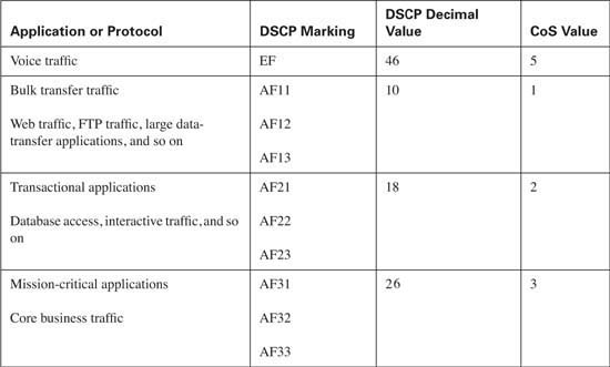
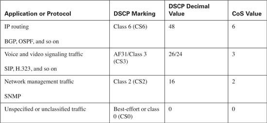
Table 10-10 lists the discussed classes and shows the Cisco best practices for classification and marking of DSCP and CoS values for each traffic type.
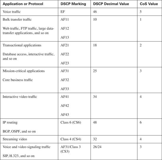
Tip Notice that voice and video signaling traffic is listed with a DSCP value of AF31/CS3. As of this writing, Cisco IP Phones mark this traffic as AF31 by default. Within Cisco, a migration is underway to change the marking from AF31 to CS3, leaving the AF3 class available for mission-critical applications. Until this migration is complete, mission-critical applications should use a DSCP value of 25.
Congestion management describes how a router or switch handles each configured class of traffic during times of congestion. If there is no congestion on the router or switch for that period in time, congestion management does not come into play. However, when buffers and queues begin to fill, the router or switch must have a means to decide the order in which traffic will be transmitted.
LLQ and CBWFQ are the preferred methods for scheduling traffic. LLQ provides a guaranteed, minimal amount of delay and jitter through the router, making LLQ ideal for transporting voice and interactive video traffic.
CBWFQ is used to guarantee that each configured traffic class has a minimal level of bandwidth, thereby preventing starvation for each configured class of traffic.
Table 10-11 lists the congestion management best practices. Remember that the percentage of bandwidth allocated depends upon the applications on your network. In many cases, all the listed classes are not needed, as this allows for the bandwidth assigned to the unnecessary class to be allocated to a necessary class. If excess bandwidth is available, it is divided among the traffic classes in proportion to their configured bandwidths.
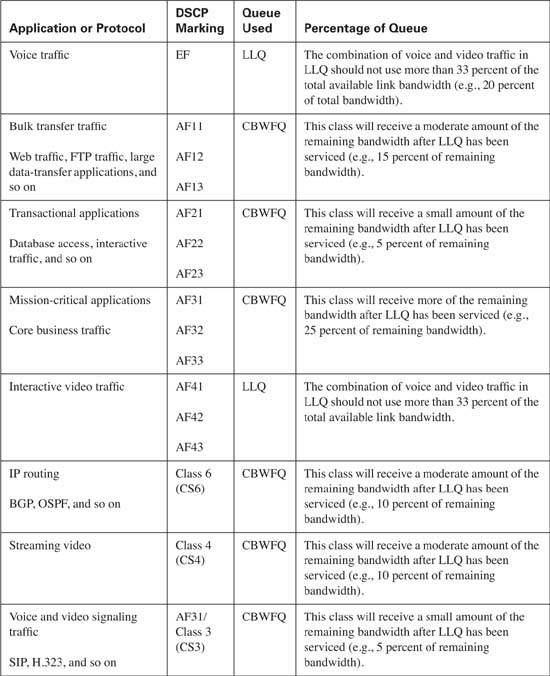
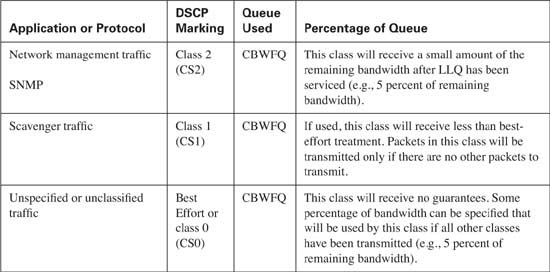
In this example the aggregate allocated bandwidth is 100 percent. By default, only 75 percent of the link bandwidth is available to LLQ/CBWFQ. If all applications on your network are accounted for and properly classified, the allocated bandwidth can be configured to use 100 percent of the link by using the max-reserved-bandwidth 100 interface command. Be aware that this command reserves all the available interface bandwidth, meaning that any unclassified traffic might face starvation if the best-effort class is not able to transmit the packet due to heavy volume.
As a design guideline, the LLQ should contain only the real-time applications on your network and should not use more than 33 percent of the total available link bandwidth. When a packet has reached the LLQ, it is scheduled, or transmitted, on a first-in, first-out (FIFO) basis from the queue. If too many packets exist in the LLQ, the benefits of QoS are negated, because each packet must wait in the LLQ for scheduling. This guideline prevents LLQ from becoming overprovisioned.
After traffic has been scheduled into the appropriate queue, you must examine the physical links that the traffic needs to traverse. In the case of a low-speed serial link, such as a 256-kbps Frame Relay link, that will transport real-time applications, traffic shaping, Link Fragmentation and Interleaving (LFI), and compressed RTP (cRTP) must be considered.
Traffic shaping is needed to prevent packets from being transmitted at a rate greater than the committed information rate (CIR) of the Frame Relay circuit. This results in packets being marked as discard eligible (DE) by the Frame Relay network and poses the potential of being dropped. Applications using TCP will retransmit the packet; however, real-time applications have no means of recovering a dropped packet. By traffic shaping the sending rate to the CIR of the interface, you can ensure that packets are not marked DE and therefore not potentially dropped.
Recall from Chapter 6, “Traffic Policing and Shaping,” that Cisco routers begin to send traffic on a Frame Relay circuit eight times a second. This results in a Tc value of 125 ms. In the worst case, a voice packet can experience a high amount of delay while waiting on the next send cycle. This can cause the voice packet to arrive too late for use and be discarded by the terminating device. To remedy this situation, the Tc value should be configured for 10 ms by stating the send cycle 100 times per second. This ensures that in the worst case a voice packet will experience only a small delay that can be compensated for by the jitter buffer in the terminating device.
Now that you are sending every 10 ms, what happens if a large data packet begins to serialize as a voice packet arrives? Even though the sending interval has been decreased, the voice packet will need to wait until the large data packet completes serialization before it can be transmitted. This too can cause the voice packet to experience a large delay. The solution to this problem is Link Fragmentation and Interleaving (LFI). LFI takes the large data packet and breaks it into smaller fragments that can be serialized more quickly. Because the recommended serialization delay of a voice packet is between 10 and 15 ms, LFI needs to be configured to fragment all packets so that each fragment can be serialized in 10 ms.
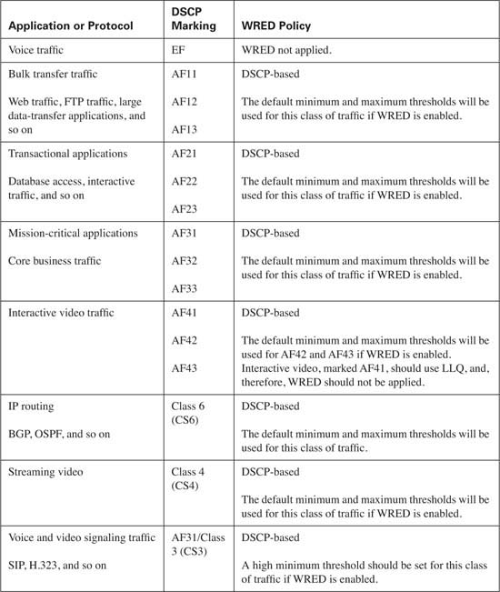
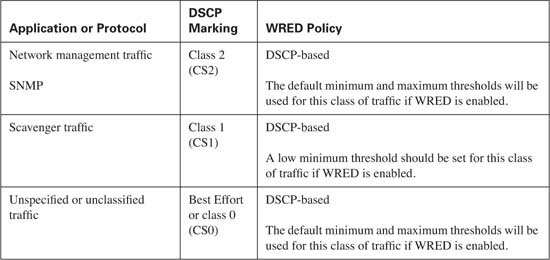
Congestion avoidance is used to randomly drop packets to prevent the assigned queue from becoming congested. This congestion results in the tail drop of all subsequent received packets. Recall from Chapter 7, “Congestion Avoidance Through Drop Policies,” that WRED uses a minimum threshold, average queue depth, and maximum threshold to determine if a packet should be dropped from a queue, while the mark probability denominator is used to calculate the number of packets that will be discarded.
As a rule of thumb, WRED performs more effectively when applied to a CBWFQ that services TCP applications, because these applications have the capability to retransmit lost packets. Some classes of traffic, such as best-effort and bulk transfer traffic, are good candidates for WRED. Real-time applications, which reside in the low latency queue, should never be eligible for WRED.
The type of applications present in each class of traffic and the potential congestion of the queues determine how WRED should be configured. By using the default DSCP drop probability, WRED has a means of randomly dropping packets from traffic flows that have been classified by the administrator as applications that can sustain the loss. From the default drop probability, a baseline can be gathered over time. The minimum and maximum thresholds and mark probability denominator can then be modified as needed.
Policing limits unwanted traffic in the network by defining an allowable limit and specifying what action should be taken on traffic that exceeds the specified limit.
Unlike classification, congestion management, and to some extent congestion avoidance, there are no steadfast rules for policing that cover most situations. With the possible exception of scavenger traffic, no class of traffic requires policing. Policing should be used to limit the amount of inbound bandwidth used by acceptable traffic. The decision to use policing in the enterprise is typically based upon the need to maximize current throughput without purchasing additional bandwidth. In a service provider network, policing is typically used to limit the sending rate of the enterprise customer and either drop or remark nonconforming traffic.
Policing varies greatly between networks. By gathering a baseline of your network and understanding the acceptable sending rates of each traffic class, you can map a strategy for policing. For policing strategies available with a Cisco infrastructure, see Chapter 6.
The following four QoS case studies examine Cisco best practices for QoS implementations in a typical converged network given the following setups:
![]() Enterprise campus QoS implementations
Enterprise campus QoS implementations
![]() Enterprise (CE) to service provider (PE) WAN QoS implementations
Enterprise (CE) to service provider (PE) WAN QoS implementations
![]() Service provider (PE) to enterprise (CE) WAN QoS implementations
Service provider (PE) to enterprise (CE) WAN QoS implementations
![]() Service provider backbone QoS implementations
Service provider backbone QoS implementations
Before you configure QoS in a campus environment, it is important to have a hieratical and redundant campus design to support real-time applications. This design should consist of an access layer, a distribution layer, and a core, as shown in Figure 10-4.
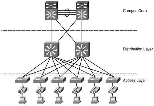
Typically, IP phones and client PCs are connected to access layer switches. The distribution layer switches provide connectivity and redundancy for access layer switches. This setup allows for the scalability and aggregation of access layer switches, which can provide IP phone and client connections for many floors or buildings. The core of the campus network typically consists of very high-speed links that connect the distribution layer switches. Due to these high-speed links, congestion is typically not an issue in the campus core. If the core of your network has the potential for congestion, scheduling should be configured to prioritize desired traffic.
Classification and marking should never be performed in the core of the network, because all traffic received by the core should arrive marked from a trusted source. This section addresses the QoS requirements for the access and distribution layers of the campus LAN. QoS for the core of the campus network will not be discussed.
Table 10-13 lists the QoS components that need to be configured in the access layer and distribution layer of the campus LAN.
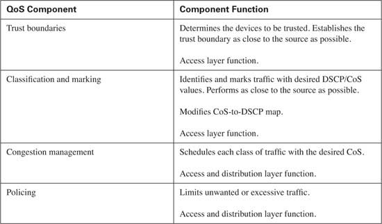
The Cisco Catalyst 2950 and 3550 are common access layer switches seen in converged networks today. Chapter 9, “Lan QoS,” discusses the QoS configuration options of the Catalyst 2950. In Figure 10-4, assume that the access layer switches are Catalyst 3550 switches and the distribution layer consists of Catalyst 4500 switches using a Supervisor III module.
By default, the switch transmits packets on a FIFO basis without regard for the received markings on each frame. To begin QoS configuration, you must enable QoS on the access layer switch. This is achieved with the global mls qos command. After you enable QoS, you need to determine which devices on your network you will trust. You should configure a trust boundary as close to the source as possible. This means the access layer should contain the initial trust boundary by extending trust to desired devices, such as IP phones, while not extending trust to undesired devices, such as the attached PCs. This is accomplished using the mls qos trust device cisco-phone command on the interface that connects a Cisco IP Phone. Additionally, you need to trust the DSCP or CoS markings received from the distribution layer. This is accomplished by placing either the mls qos trust dscp command or the mls qos trust cos command on the interface that connects to the distribution layer switch. In this example, both the access layer and the distribution layer switches have the capability to read the received DSCP marking, so trust will be based upon DSCP. Example 10-1 shows the configuration necessary to establish the trust boundary.
Example 10-1 Catalyst 3550 Access Layer Switch Trust Boundaries
description Connection to Distribution Layer
switchport trunk encapsulation dot1q
switchport mode trunk
no ip address
mls qos trust dscp
!
interface FastEthernet0/2
description Connection to IP Phone
switchport voice vlan 5
no ip address
mls qos trust device cisco-phone
!
After you establish the trust boundary, you can begin to classify desired traffic into the proper traffic groups. Assume that this network carries Cisco voice traffic as well as mission-critical data, transactional data, bulk data, and best-effort traffic. Table 10-14 lists the recommended DSCP and CoS marking for each of these traffic classes.
Cisco IP Phones have the capability to mark both voice signaling and voice media traffic; however, other applications, such as Cisco Softphone and certain Computer Telephony Integration (CTI) applications, may not. To ensure that each device or application in the network receives the proper treatment for all voice signaling and media traffic, it is important to classify this traffic using some other means:
![]() All Cisco voice media streams are carried across the network in UDP/RTP packets that use the port range of 16384 to 32767.
All Cisco voice media streams are carried across the network in UDP/RTP packets that use the port range of 16384 to 32767.
![]() All Cisco Skinny voice signaling packets are transported across the network using the TCP port range of 2000 to 2002.
All Cisco Skinny voice signaling packets are transported across the network using the TCP port range of 2000 to 2002.
![]() H.323 signaling packets use TCP port 1720 as well as the TCP range of 11000 to 11999.
H.323 signaling packets use TCP port 1720 as well as the TCP range of 11000 to 11999.
![]() Media Gateway Control Protocol (MGCP) uses the UDP port 2427.
Media Gateway Control Protocol (MGCP) uses the UDP port 2427.
These protocols and port numbers can be used to classify this traffic. Similarly, the protocol and port number of traffic that comprises the mission-critical, transaction, bulk data, and network-management traffic can be used for classification. The best-effort class will match all other traffic. Example 10-2 shows the configuration necessary to classify and mark the desired traffic.
Example 10-2 Catalyst 3550 Access Layer Switch Classification
match access-group 100
class-map match-all voice-signaling
match access-group 101
class-map match-all mission-critical
class-map match-all transactional
match access-group 103
class-map match-all bulkdata
match access-group 104
class-map match-all netmanage
match access-group 105
class-map match-all besteffort
match any
!
policy-map mark-traffic
class voice-media
set ip dscp ef
class voice-signaling
set ip dscp 24
class mission-critical
set ip dscp af31
class transactional
set ip dscp af21
class bulkdata
set ip dscp af11
class netmanage
set ip dscp cs2
class besteffort
set ip dscp 0
!
access-list 100 permit udp any any range 16384 32767
access-list 101 permit tcp any any range 2000 2002
access-list 101 permit tcp any any eq 1720
access-list 101 permit tcp any any range 11000 11999
access-list 102 permit <Protocol / port for Mission Critical Traffic>
access-list 103 permit <Protocol / port for Transactional Traffic>
access-list 104 permit <Protocol / port for Bulk Data Traffic>
access-list 105 permit <Protocol / port for Network Management Traffic>
Finally, the service-policy input command is used to enable classification for each desired interface that connects to a Cisco IP Phone of a client PC, as shown in Example 10-3.
Example 10-3 Catalyst 3550 Access Layer Service-Policy Input
interface FastEthernet0/2
description Connection to IP Phone
switchport voice vlan 5
no ip address
service-policy input mark-traffic
mls qos trust device cisco-phone
When the access layer switch receives a packet with a DSCP value from a trusted interface or device, it automatically assigns a CoS value to the packet. Likewise, if the switch receives a packet with a CoS value, it automatically assigns a DSCP value to the packet. These assigned values can be modified using the mls qos map dscp-cos and mls qos map cos-dscp commands, respectively. Because DSCP uses 6 bits, as opposed to the 3 bits used by CoS, a wider range of DSCP values can be mapped to a single CoS value. For example, a received packet marked AF31, AF32, or AF33 will share the same CoS value of 3. Typically, this is desired behavior and so the DSCP-to-CoS map does not usually need to be modified. The CoS-to-DSCP map, however, has fewer options. By default, a received packet with a CoS value of 5 will be marked with a DSCP value of decimal 40, which is not the same as DSCP EF (decimal 46). Because a CoS value of 5 typically represents the marking for voice traffic, which should also be marked with a DSCP value of EF, you need to modify the CoS-to-DSCP map. The mls qos map cos-dscp 0 8 16 24 32 46 48 56 command makes this modification.
Tip Notice that the CoS value of 3 is mapped to DSCP CS3 (decimal 24) by default. This is different than the current DSCP value AF31 (decimal 26) marked by the Cisco IP Phone today and more in line with the Cisco migration strategy of changing the voice signaling DSCP marking from AF31 (decimal 26) to CS3 (decimal 24), as discussed in the earlier “Classification and Marking Best Practices” section of this chapter. To keep the voice signaling traffic consistent with the way Cisco IP Phones are marking traffic today, use the mls qos map cos-dscp 0 8 16 24 32 46 48 56 command.
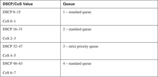
When trust, classification, and marking have been established, you need to determine the CoS each type of traffic will receive. To properly configure scheduling, it is important to understand the transmit-queuing capability of the access layer switches used in your network. Separating traffic into distinct hardware queues within the access layer switch is a requirement. The Catalyst 3550 in the sample network offers one strict priority transmit queue and three standard transmit queues (1p3q2t). Each standard queue has two drop thresholds and is serviced using a WRR scheduling method. This allows real-time applications, such as voice, to receive a guaranteed delay, jitter, and bandwidth, while the remaining three queues will receive a guaranteed bandwidth. Admission into each queue is dependant upon the CoS value received. Table 10-15 shows the default queue admission on a Catalyst 3550.
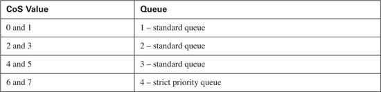
Notice that Ethernet frames marked with a CoS value of 5 will be placed in standard queue 3. Because Cisco IP Phones mark voice media traffic with a CoS value of 5 by default, this means that all voice media traffic will not be placed into the strict priority queue. The wrr-queue cos-map command remaps received with a CoS value of 5 into the strict priority queue, queue number 4. Example 10-4 shows the necessary configuration.
Example 10-4 Catalyst 3550 Access Layer WRR-Queue CoS-Map
interface FastEthernet0/1
description Connection to Distribution Layer
switchport trunk encapsulation dot1q
switchport mode trunk
no ip address
mls qos trust dscp
wrr-queue cos-map 4 5
priority-queue out
!
interface FastEthernet0/2
description Connection to IP Phone
switchport voice vlan 5
no ip address
mls qos trust device cisco-phone
wrr-queue cos-map 4 5
priority-queue out
spanning-tree portfast
!
Notice that the priority-queue out command is also placed under the interface. This command instructs the switch to treat queue number 4 as the strict priority queue. Without this command the Catalyst 3550 treats queue number 4 as a standard queue. After the strict priority queue has been defined and real-time traffic has been scheduled, you need to determine the scheduling treatment received for the remaining traffic. Assume that it has been determined that queue 1, consisting of frames marked with CoS values 0 and 1, transmits 25 frames per interval. Queue 2, consisting of frames marked with CoS values 2 and 3, transmits 50 frames per interval. Finally, queue 3, consisting of frames marked with a CoS value of 4, transmits 10 frames per interval. The wrr-queue bandwidth command can be placed upon the interface to specify the number of packets each queue is allowed to transmit before the next queue is serviced. Example 10-5 shows how the WRR bandwidth is configured for this example.
Remember that this is just an example. Scheduling treatment will depend on the QoS requirements of the applications that exist on your network.
Notice that queue 4 has been configured to transmit 15 frames per interval. In a network that contains real-time applications, this will not suffice. Thankfully, the priority-queue out command overrides this configuration, changing queue 4 from a standard WRR queue to a strict priority queue. The WRR configuration of queue 4 comes into play only if the priority-queue out command is removed from the interface.
At this point, the access layer of the campus network has been configured to classify traffic into groups and provide for the QoS requirements of the desired applications. From the access layer, packets flow to the distribution layer switches. The distribution layer of the example network consists of Catalyst 4500 switches using Supervisor III modules. Because the distribution layer trusts markings received from the trust boundaries established in the access layer, you do not need to reclassify received traffic. This simplifies the QoS configuration of the distribution layer, by requiring only the configuration of scheduling the predefined traffic classes and the policing of any unwanted traffic.
By default, QoS is disabled on the Catalyst 4500. To enable QoS, use the global qos command. The qos trust dscp interface command is used on the interfaces that connect to the access layer in the example network. This allows the distribution layer switches to trust the received DSCP marking. Example 10-6 shows the distribution configuration needed to extend trust to the access layer.
Example 10-6 Catalyst 4500 Trust
description Connection to Access Layer
switchport trunk encapsulation dot1q
switchport mode trunk
The Supervisor III module offers one strict priority transmit queue and three standard transmit queues (1p3q2t). Each standard queue has two drop thresholds and is serviced using a WRR scheduling method. This allows real-time applications, such as voice, to receive a delay, jitter, and bandwidth guarantee, while the remaining three queues receive only a guaranteed bandwidth. Admission into each queue is dependant upon the DSCP or CoS value received. Table 10-16 shows the default queue admission on a Catalyst 4500 using a Supervisor III module.
By default, each of the four queues will be allowed to transmit for 25 percent of the interface before moving to the next queue. As with the access layer switches, this will not provide the priority needed for real-time applications. To provide the necessary prioritization, you need to enable the strict priority queue. To enable the strict priority queue on the Catalyst 4500, use the tx-queue 3 and priority out commands on each desired interface. Example 10-7 shows the necessary configuration.
Example 10-7 Catalyst 4500 Strict Priority Queuing
description Connection to Access Layer
switchport trunk encapsulation dot1q
switchport mode trunk
qos trust dscp
priority high
As with the access layer switches, the distribution layer switches have the capability to map a received CoS value to a DSCP value or a received DSCP value to a CoS value. If trust is based upon the received DSCP value of a packet, the appropriate CoS value will be placed upon the packet. If trust is based upon the CoS value received, the CoS-to-DSCP map may need to be modified. For example, a received CoS value of 5 will result in a DSCP value of decimal 40, which is not the same as DSCP EF or decimal 46. You can change the CoS-to-DSCP mapping with the global qos map cos 5 to dscp 46 command.
Because the distribution layer provides aggregation service for all the access layer switches, this is an ideal place to limit traffic that might threaten congestion in the core. For example, assume that there is a large amount of unwanted FTP traffic, yet the core of your network is provisioned for a maximum of 5 Mbps of FTP traffic. The distribution layer can be used to limit the received FTP traffic to 5 Mbps and drop any additional FTP traffic received. Example 10-8 shows how this is accomplished.
Example 10-8 Catalyst 4500 Policing
match access-group 2
!
policy-map policeftp
class policeftp
!
interface GigabitEthernet1/1
description Connection to Access Layer
switchport mode trunk
qos trust dscp
tx-queue 3
priority high
!
access-list 2 permit <IP Address of FTP server>
!
By identifying the desired traffic to police, defining the policed limit, and applying the limit to the interface, the distribution layer can prevent the transport of any unwanted traffic into the core of the campus network.
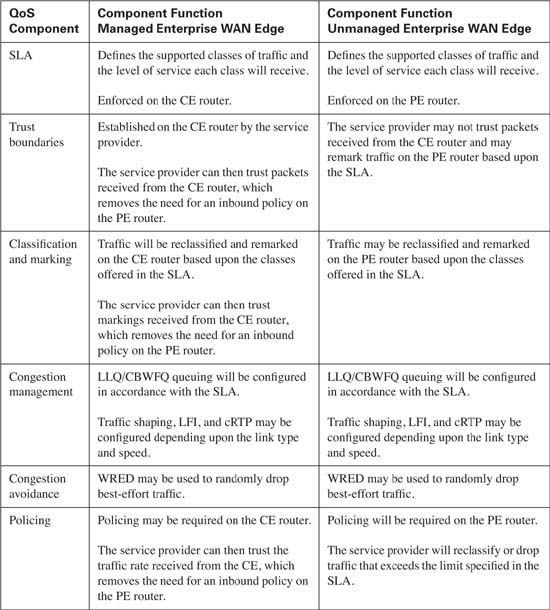
As traffic leaves the campus LAN and enters the enterprise WAN edge router, also known as the CE router, for transport across the service provider’s network, the question of QoS configuration on the CE router arises. The exact QoS configuration depends upon who has configuration control of the CE router. In some cases, this router is under the administrative control of the enterprise, while in other cases, the service provider manages the CE router. The major difference between the two configurations becomes mostly a matter of trust. If the CE router is under the control of the enterprise, the DSCP markings received from the campus LAN can be trusted because the same administrative control extends to the campus LAN. However, if the service provider manages the CE router, a trust boundary will be established on the CE router because the service provider has no control over the campus LAN. In either case, some fundamental QoS configurations are consistent. Table 10-17 lists the QoS components required on the CE router.
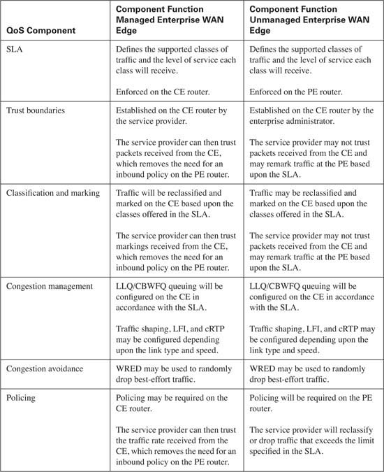
Notice that the SLA agreement is instrumental in each QoS component required. This is because the SLA provides the roadmap that will be used for all traffic that traverses the service provider’s network. From this roadmap, QoS configuration for the CE router can be developed. Assume that Table 10-18 represents the SLA that has been reached between the enterprise and the service provider.
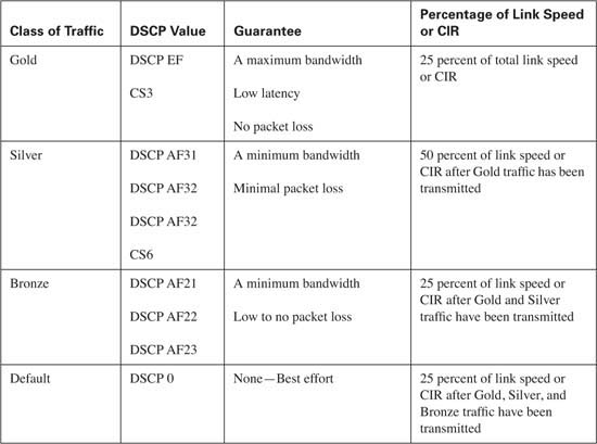
In this example, the service provider will place traffic into each of these classes based upon the received DSCP value of each packet.
Assume that the link between the enterprise and the service provider is a Frame Relay circuit with a port speed and CIR of 256 kbps, as shown in Figure 10-5.
With the SLA and network topology in place, you can begin to build the required QoS configurations.
Classification of the enterprise traffic into the Gold, Silver, Bronze, and Default groups must be performed first. Because the campus LAN has more than four traffic classes defined, some classes must be combined to classify all traffic within the four classes the service provider offers in this example. Combining these classes requires that some traffic be reclassified and marked on the CE router. Table 10-19 lists the enterprise traffic classes, the original campus LAN DSCP marking, and the reclassified DSCP marking on the CE, if needed.
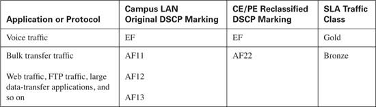
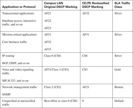
In this example, Gold traffic will consist of voice media and call setup traffic. Note that call setup traffic will use the marking of DSCP CS3 in this example to allow mission-critical traffic to use the AF31 marking. This assumes that call setup traffic has been marked as CS3 in the campus LAN. Silver traffic will consist of all mission-critical and transactional enterprise application traffic as well as IP routing traffic. Bronze traffic will consist of bulk transfer data and network management traffic. Default, or best-effort, traffic will consist of all other nonclassified traffic.
Notice that some application traffic, such as voice media traffic, does not need to be reclassified, because the DSCP marking of EF allows the voice media traffic admittance into the Gold traffic class. However, other application traffic will need to be remarked to gain admittance into the desired traffic class. For example, bulk transfer data traffic needs to be reclassified from AF1x to AF22 to gain admittance into the Bronze class.
If the CE is controlled by the enterprise, the classifications can be trusted from the campus LAN and passed on to the service provider, or they can be reclassified using MQC, NBAR, access lists, or any combination of these on the CE router before delivery to the service provider. If the service provider manages the CE router, traffic will most likely be reclassified using NBAR or access lists as specified in the SLA. This example assumes that the CE is managed by the enterprise. DSCP marking from the campus LAN is trusted and MQC is used to reclassify traffic into the Gold, Silver, Bronze, and Default traffic classes supported by the SLA. Example 10-9 shows this configuration.
Example 10-9 CE Classification
match ip dscp ef
class-map match-any voice-signaling
match ip dscp cs3
class-map match-any mission-critical
match ip dscp af31
match ip dscp af32
match ip dscp af33
class-map match-any transactional
match ip dscp af21
match ip dscp af22
match ip dscp af23
class-map match-any bulkdata
match ip dscp af11
match ip dscp af12
match ip dscp af13
class-map match-any routing
match ip dscp cs6
class-map match-any netmanage
match ip dscp cs2
!
policy-map OutPolicy
class voice-media
set ip dscp ef
class voice-signaling
set ip dscp cs3
class mission-critical
set ip dscp af31
class transactional
set ip dscp af32
class bulkdata
set ip dscp af22
class routing
set ip dscp cs6
class netmanage
set ip dscp af21
class class-default
set ip dscp 0
!
Notice that some classes, such as the bulkdata class, have been remarked, while other classes, such as the voice-media class, remain unchanged. This allows the CE router to classify the traffic into groups supported in the SLA.
Queuing will use a combination of LLQ and CBWFQ in the policy-map command. LLQ will guarantee that all Gold traffic will receive 25 percent of the CIR. Because the Gold class consists of the voice-media class and the voice-signaling class, the allocated 25 percent of the link must be split between these two classes. In this example, the voice-media class will receive 21 percent of the link, while the voice-signaling class will receive 4 percent of the link.
CBWFQ will be used on the Silver and Bronze classes to guarantee that a minimum amount of bandwidth will be available for each enterprise traffic class.
The Silver class will consist of IP routing updates, mission-critical data, and transactional data traffic. All enterprise traffic classes in the Silver class will be allocated a minimum of 50 percent of the link after the Gold traffic class has been transmitted. In this example, IP routing updates will receive 5 percent, mission-critical traffic will receive 30 percent, and transaction data traffic will receive 15 percent.
The Bronze class will consist of bulk transfer data and network management traffic. All enterprise traffic classes in the Bronze class will be allocated a minimum of 25 percent of the link after the Gold traffic class has been transmitted. In this example, the bulk data class will receive 20 percent of the link, while network management traffic will receive 5 percent of the link.
The Default class will consist of all unclassified and best-effort traffic. This class will receive 25 percent of the link after the Gold class has been transmitted.
Example 10-10 shows the CE queuing configuration.
Example 10-10 CE Queuing
class voice-media
class voice-signaling
class mission-critical
class transactional
class bulkdata
Notice that the priority percent and bandwidth percent remaining commands are used to specify the amount of bandwidth available to each class of traffic. These commands allow you to specify bandwidth per class without having to specify the exact amount of bandwidth. For example, 25 percent of the 256-kbps CIR is 64 kbps. The 64 kbps available to the priority queue could have been divided between the voice-media and voice-signaling classes and specified in terms of bandwidth to accomplish this same goal. Using the percent and percent remaining options simplifies QoS configuration because a single template can now be used across the enterprise.
Because this example network has a low-speed Frame Relay link, traffic shaping, LFI, and cRTP must be taken into consideration.
Traffic shaping will be configured to limit the total traffic sent to the CIR value of 256 kbps. This will prevent any frame from being marked as discard eligible and possibly being dropped by the service provider in time of congestion. While TCP traffic has a means of recovering lost packets, real-time applications do not.
Because delay is a major concern with real-time applications, it is important to minimize the serialization delay for the voice traffic in this network. The recommended serialization delay for voice packets is 10 to 15 ms. The recommended delay can be exceeded if a voice packet is waiting for a larger data packet to serialize before it can be transmitted. To minimize the serialization delay, all packets must be sized so that they will serialize within the 10–15 ms window. Modifying the default TC value and using LFI will accomplish this. For this example, TC will be modified to 10 ms by configuring the Bc to 2560, while Frame Relay fragmentation will be added to ensure that all packets are no larger than 320 bytes. Because the network in this example contains a slow Frame Relay link, the RTP headers can be compressed to conserve bandwidth. Example 10-11 shows the configuration needed to address these concerns.
Example 10-11 CE Traffic Shaping, LFI, and cRTP
interface Serial0/0.1 point-to-point
description to SP PE router
ip address 10.254.14.2 255.255.255.252
frame-relay interface-dlci 115
map-class frame-relay FR-Shape
frame-relay bc 2560
frame-relay mincir 256000
service-policy output OutPolicy
frame-relay ip rtp header-compression
Finally, congestion avoidance should be configured on the bulk data and default, or Best Effort, traffic classes. This helps prevent tail drop in the default by randomly dropping packets from different flows in the bulk data and default classes. Example 10-12 shows this configuration.
Example 10-12 CE Congestion Avoidance
policy-map OutPolicy
class voice-media
priority percent 21
set ip dscp ef
class voice-signaling
priority percent 4
set ip dscp cs3
class mission-critical
bandwidth percent remaining 30
set ip dscp af31
class transactional
bandwidth percent remaining 15
set ip dscp af32
class bulkdata
bandwidth percent remaining 20
set ip dscp af22
bandwidth percent remaining 5
set ip dscp cs6
Example 10-13 pulls the entire configuration together, showing the total QoS configuration of the CE router in the sample network.
Example 10-13 CE QoS Configuration
match ip dscp ef
class-map match-any voice-signaling
match ip dscp cs3
class-map match-any mission-critical
match ip dscp af31
match ip dscp af32
match ip dscp af33
class-map match-any transactional
match ip dscp af21
match ip dscp af22
match ip dscp af23
class-map match-any bulkdata
match ip dscp af11
match ip dscp af12
match ip dscp af13
class-map match-any routing
match ip dscp cs6
class-map match-any netmanage
match ip dscp cs2
!
policy-map OutPolicy
class voice-media
priority percent 21
set ip dscp ef
class voice-signaling
priority percent 4
set ip dscp cs3
class mission-critical
bandwidth percent remaining 30
set ip dscp af31
class transactional
bandwidth percent remaining 15
class bulkdata
bandwidth percent remaining 20
set ip dscp af22
bandwidth percent remaining 5
set ip dscp cs6
class netmanage
bandwidth percent remaining 5
set ip dscp af21
class class-default
set ip dscp 0
random-detect dscp-based
!
interface Serial0/0
description to SP PE router
encapsulation frame-relay
frame-relay traffic-shaping
!
interface Serial0/0.1 point-to-point
ip address 10.254.14.2 255.255.255.252
frame-relay interface-dlci 115
class FR-Shape
!
map-class frame-relay FR-Shape
frame-relay cir 256000
frame-relay bc 2560
frame-relay be 0
frame-relay mincir 128000
service-policy output OutPolicy
frame-relay fragment 320
frame-relay ip rtp header-compression
Example 10-13 examined the QoS configuration of the CE router from the perspective of sending packets to the PE router. The assumption here is that traffic arriving from the PE router will be marked in accordance with the SLA. The use of NBAR or access lists will be required to remark the mission-critical data, transactional data, bulk transfer data, and network management traffic to the original campus LAN classification. The exact configuration required is dependant upon the applications that comprise each class.
The previous section discusses how traffic is treated as it leaves the CE router. This section looks at the treatment traffic receives on the service provider’s WAN edge (PE) router. As with the previous section, the exact configuration depends upon the configuration control of the CE router.
Table 10-20 lists the QoS components required on the PE router.
As with the CE router QoS configuration, the PE router uses the SLA to determine the QoS configuration needed.
The service provider can trust the DSCP values received from the CE, or remark the values using NBAR or access lists based on the terms of the SLA. For this example, assume that the service provider trusts the DSCP value on each packet as long as the marking is consistent with the acceptable values specified in the SLA. Any other DSCP value received will be rewritten with a DSCP value of 0. Example 10-14 shows the configuration needed on the PE to accomplish this.
Example 10-14 PE DSCP Classification and Marking
match ip dscp ef
match ip dscp cs3
class-map match-any silver
match ip dscp af31
match ip dscp af32
match ip dscp cs6
class-map match-any bronze
match ip dscp af22
match ip dscp af21
!
policy-map InPolicy
class gold
class silver
class bronze
class class-default
In this example network, the CE router is under the control of the enterprise. The service provider has no control over the amount of traffic being sent in each class. Therefore, the service provider must use policing to either drop or remark nonconforming traffic. The Gold class will be policed to 25 percent of the link. Nonconforming traffic received in this class will be dropped. The Silver class will be policed to a minimum of 50 percent of the link. Nonconforming traffic received in this class will be remarked to the Bronze class and sent. The Bronze class will be policed to a minimum of 25 percent of the link. Nonconforming traffic received in this class will be remarked to the Default class and sent. The Default class will not be policed. Example 10-15 shows the configuration needed on the PE to accomplish this.
Example 10-15 PE Policing
class gold
conform-action transmit
exceed-action drop
conform-action transmit
exceed-action set-dscp-transmit af22
conform-action transmit
exceed-action set-dscp-transmit 0
set ip dscp 0
So far, the discussion has focused on using DSCP values on the PE. This implies that the service provider’s core network is using IP routing to pass along the DSCP value from router to router. If the service provider uses Multiprotocol Label Switching (MPLS), the MPLS experimental bit is the preferred marking. By mapping the DSCP value to the appropriate MPLS experimental value, the service provider can maintain the separate classes of service across the MPLS backbone. Example 10-16 shows how this might be configured.
Example 10-16 PE MPLS Classification and Marking
class gold
police percent 25
conform-action set-mpls-exp-transmit 5
exceed-action drop
class silver
police percent 50
conform-action set-mpls-exp-transmit 4
exceed-action set-mpls-exp-transmit 3
class bronze
police percent 25
conform-action set-mpls-exp-transmit 3
exceed-action set-mpls-exp-transmit 0
class class-default
Because traffic shaping, LFI, and cRTP have been configured on the CE router, the PE router must also be configured to reflect these values. Example 10-17 shows the configuration of traffic shaping, LFI, and cRTP on the PE router.
Example 10-17 PE Policing
description to Customer's CE router
encapsulation frame-relay
interface Serial0/0.1 point-to-point
ip address 10.254.14.1 255.255.255.252
frame-relay interface-dlci 125
map-class frame-relay FR-Shape
frame-relay cir 256000
frame-relay bc 2560
frame-relay be 0
frame-relay mincir 128000
service-policy input InPolicy
frame-relay ip rtp header-compression
Finally, WRED will be configured on the Silver, Bronze, and Default classes to prevent tail drop from occurring. Example 10-18 shows the configuration needed to enable WRED.
Example 10-18 PE Congestion Avoidance
class gold
police percent 25
conform-action transmit
exceed-action drop
class silver
police percent 50
conform-action transmit
exceed-action set-dscp-transmit af22
police percent 25
conform-action transmit
exceed-action set-dscp-transmit 0
bandwidth percent remaining 25
set ip dscp 0
The preceding configurations examine how traffic received by the PE router is treated in accordance to the sample SLA. You must also consider traffic being sent from the PE to the CE. Because all traffic being sent from the PE should already be classified and marked with the appropriate DSCP value, this becomes a matter of queuing and congestion avoidance. You can create an output policy map, similar to the policy map used in the CE router, to define the queuing and WRED configurations. Example 10-19 shows the configuration for the output policy map on the PE router.
Example 10-19 PE-to-CE Output Policy Map
class gold
class bronze
class class-default
!
interface Serial0/0
description to Customer's CE router
encapsulation frame-relay frame-relay
traffic-shaping
!
interface Serial0/0.1 point-to-point
ip address 10.254.14.1 255.255.255.252
frame-relay interface-dlci 125
class FR-Shape
!
map-class frame-relay FR-Shape
frame-relay cir 256000
frame-relay bc 2560
frame-relay be 0
frame-relay mincir 256000
service-policy input InPolicy
frame-relay ip rtp header-compression
Notice that WRED was also configured on the Silver, Bronze, and Default traffic classes. This mirrors the configuration on the service provider’s input policy map.
Example 10-20 pulls the entire configuration together, showing the total QoS configuration of the PE router in the sample network.
Example 10-20 CE QoS Configuration
match ip dscp ef
match ip dscp cs3
class-map match-any silver
match ip dscp af31
match ip dscp af32
match ip dscp cs6
class-map match-any bronze
match ip dscp af22
match ip dscp af21
!
policy-map InPolicy
class gold
police percent 25
conform-action transmit
exceed-action drop
class silver
police percent 50
conform-action transmit
exceed-action set-dscp-transmit af22
random-detect dscp-based
class bronze
police percent 25
conform-action transmit
exceed-action set-dscp-transmit 0
random-detect dscp-based
class class-default
bandwidth percent remaining 25
set ip dscp 0
random-detect dscp-based
policy-map OutPolicy
class gold
priority percent 25
class silver
bandwidth percent remaining 50
random-detect dscp-based
class bronze
bandwidth percent remaining 25
random-detect dscp-based
class class-default
bandwidth percent remaining 25
random-detect dscp-based
!
interface Serial0/0
description to Customer's CE router
encapsulation frame-relay
frame-relay traffic-shaping
!
interface Serial0/0.1 point-to-point
ip address 10.254.14.1 255.255.255.252
frame-relay interface-dlci 125
class FR-Shape
!
map-class frame-relay FR-Shape
frame-relay cir 256000
frame-relay bc 2560
frame-relay be 0
frame-relay mincir 256000
service-policy input InPolicy
service-policy output OutPolicy
frame-relay fragment 320
frame-relay ip rtp header-compression
Note that the configuration in Example 10-20 assumes that the service provider is using DSCP instead of the MPLS experimental bit to mark traffic across the service provider backbone.
The service provider’s backbone typically consists of very high-speed links. Traditionally, service providers have planned for capacity on these links by provisioning double the amount of bandwidth for each link. For example, if a link averages 10 Gbps of data, it would be provisioned for a capacity of 20 Gbps of data. Although this will handle the traffic load on average, it offers no protection for real-time applications in times of heavy congestion. Assume that a denial-of-service attack is launched and all traffic is carried across this link. This link could quickly become saturated with traffic. Without a means of separating traffic into desired groups that can be prioritized, all applications on the 20-Gbps link would suffer. Implementing QoS in the service provider’s backbone can prevent this issue from happening.
The service provider’s network consists of Provider Edge (PE) and Provider Core (P) routers. The P routers make up the core of the backbone, while the PE routers connect the backbone to their customer’s CE routers. Figure 10-6 illustrates a typical service provider backbone model.
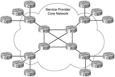
The service provider’s backbone can use IP routing or MPLS to transport packets from network to network. In an MPLS network, the MPLS experimental bits are used to separate traffic classes, whereas DSCP is used to separate traffic classes in an IP network. This section discusses the configuration of the service provider’s network using DSCP.
The service provider’s backbone consists of high-speed links, which means there is no need for traffic shaping, LFI, or cRTP between the PE and P routers.
Trust boundaries are established on the PE routers. This frees the P routers from the task of classification, marking, and policing. All classification, marking, and policing in a service provider’s backbone should be configured on the PE router. The previous section examined the inbound and outbound configuration of classification, marking, and policing needed on the PE router to support the four separate classes of traffic specified in the sample SLA. QoS configuration from the PE router to the P router and from the P router to the PE router becomes a matter of queuing and congestion avoidance for the four defined classes of traffic.
The queuing method used in the backbone will depend upon the type of router installed. Cisco Gigabit Series Routers (GSRs) use Modified Deficit Round Robin (MDRR) for queuing, whereas other routers, such as the Cisco 7500 Series routers, use LLQ for queuing. This example assumes that 7500 Series routers make up the service provider’s backbone.
The same output policy map created in the previous section, “Service Provider (PE) to Enterprise (CE) WAN QoS Implementations,” can be used to perform queuing and congestion avoidance from the PE router to the P router. This output policy provides the queuing specified in the sample SLA for each supported class of traffic and enables WRED on the Silver, Bronze, and Default classes of traffic. Example 10-21 shows this configuration.
Example 10-21 PE-to-P Output Policy Map
class gold
priority percent 25
class silver
bandwidth percent remaining 50
random-detect dscp-based
class bronze
bandwidth percent remaining 25
random-detect dscp-based
class class-default
bandwidth percent remaining 25
random-detect dscp-based
!
interface POS1/0
description to P router
Because the OutPolicy policy map was created in the “Service Provider (PE) to Enterprise (CE) WAN QoS Implementations” section of this chapter, the only change required to enable the policy map is the addition of the service-policy output OutPolicy command to the interface used to connect to the P router.
To perform the necessary queuing and congestion avoidance on the P router, the P router needs to identify the four classes of traffic using the existing DSCP values. After the traffic classes have been identified, they can be queued in accordance to the sample SLA. The configuration of the P router is similar to the PE outbound configuration, as shown in Example 10-22.
Example 10-22 P-to-PE Output Policy Map
match ip dscp ef
match ip dscp cs3
class-map match-any silver
match ip dscp af31
match ip dscp af32
match ip dscp cs6
class-map match-any bronze
match ip dscp af22
match ip dscp af21
!
policy-map OutPolicy
class gold
class silver
bandwidth percent remaining 50
random-detect dscp-based
class bronze
bandwidth percent remaining 25
random-detect dscp-based
class class-default
bandwidth percent remaining 25
random-detect dscp-based
!
interface POS1/0
description to PE router
service-policy output OutPolicy
Because the P router trusts all markings received from neighbor routers, and because classification, marking, and policing will not be performed on the P router, there is no need for an inbound policy map.
The “Foundation Summary” is a collection of tables and figures that provide a convenient review of many key concepts in this chapter. For those of you already comfortable with the topics in this chapter, this summary can help you recall a few details. For those of you who just read this chapter, this review can help solidify some key facts. For any of you doing your final preparation before the exam, these tables and figures are a convenient way to review the day before the exam.
A single voice packet consists of the voice payload, an RTP header, a UDP header, an IP header, and a Layer 2 header, as shown in Figure 10-7.
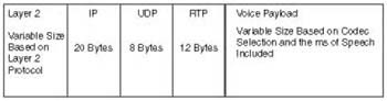
Table 10-21 lists the common G.711 and G.729 rates without including Layer 2 overhead.
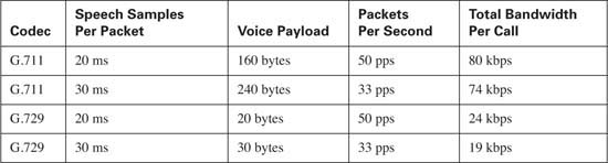
Table 10-22 lists the common G.711 and G.729 rates including Layer 2 overhead.
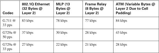
Table 10-23 lists the delay, jitter, and packet-loss requirements for transporting voice traffic.

Table 10-24 compares the QoS requirements of voice traffic with other types of traffic.
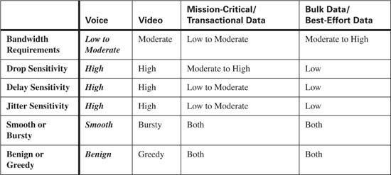
Table 10-25 lists the delay, jitter, and packet-loss requirements for transporting video traffic.
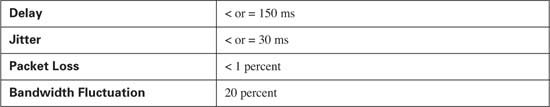
Table 10-26 lists the Cisco best practices for classification and marking of DSCP and CoS values for each traffic type.
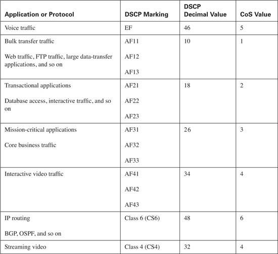
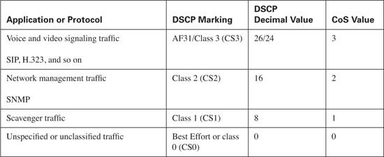
Table 10-27 lists the congestion management best practices. Remember that the percentage of bandwidth allocated depends upon the applications on your network. In many cases, all the listed classes will not be needed. This allows for the bandwidth assigned to the unnecessary class to be allocated to necessary classes.
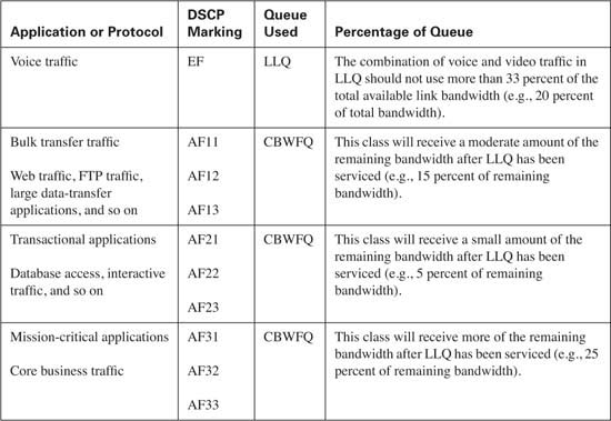
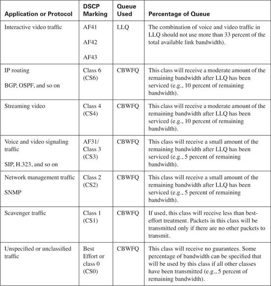
Table 10-28 lists the best practices for congestion avoidance.
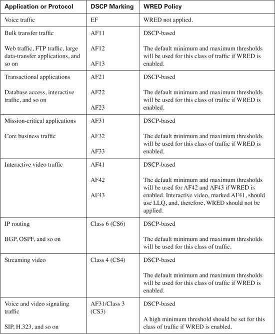
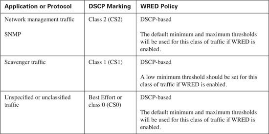
Table 10-29 lists the QoS components that need to be configured in the access layer and distribution layer of the campus LAN.
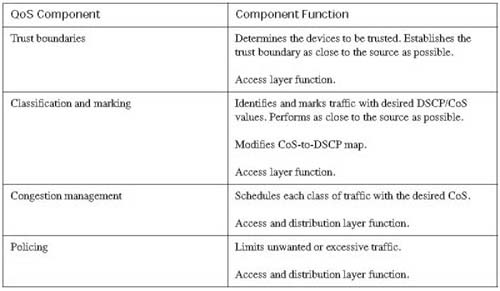
Table 10-30 lists the QoS components required on the CE router.
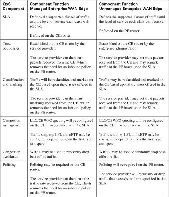
Table 10-31 lists the QoS components required on the PE router.
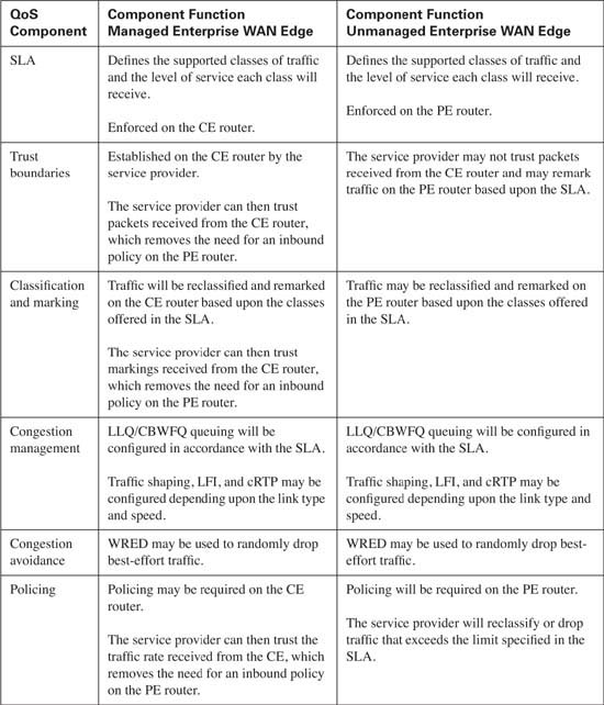
This book attempts to cover the breadth and depth of QoS as covered on the QOS exam (643-642); however, you might want to read more about topics in this chapter.
For more on the topics in this chapter:
![]() QoS Classification best practices (http://www.cisco.com/en/US/support/index.html. Then follow this link path: Technology Support > QoS (Quality of Service) > Classification & Marking > View All Documents))
QoS Classification best practices (http://www.cisco.com/en/US/support/index.html. Then follow this link path: Technology Support > QoS (Quality of Service) > Classification & Marking > View All Documents))
![]() “Implementing DiffServ for End-to-End Quality of Service Overview” (http://www.cisco.com/univercd/cc/td/doc/product/software/ios122/122cgcr/fqos_c/fqcprt7/qcfdfsrv.pdf)
“Implementing DiffServ for End-to-End Quality of Service Overview” (http://www.cisco.com/univercd/cc/td/doc/product/software/ios122/122cgcr/fqos_c/fqcprt7/qcfdfsrv.pdf)
For design-related guidance:
![]() “Cisco AVVID Network Infrastructure Enterprise Quality of Service Design” (http://cisco.com/application/pdf/en/us/guest/netsol/ns17/c649/ccmigration_09186a00800d67ed.pdf)
“Cisco AVVID Network Infrastructure Enterprise Quality of Service Design” (http://cisco.com/application/pdf/en/us/guest/netsol/ns17/c649/ccmigration_09186a00800d67ed.pdf)
|
1. |
What is end-to-end QoS? |
|
2. |
What do service providers use to contractually guarantee specific delay, jitter, and packet loss to their customers? |
|
3. |
When would an SLA be offered on a per PVC basis? |
|
4. |
In a Cisco IP Telephony environment, which codec is best suited for the LAN? |
|
5. |
In a Cisco IP Telephony environment, which codec is best suited for the WAN? |
|
6. |
By default, how many milliseconds of speech are placed into every packet in a voice media stream? |
|
7. |
How much bandwidth is required to transport a G.729 VoIP call @ 50 packets per second over a Frame Relay circuit? Assume that cRTP and VAD are not enabled. |
|
8. |
Enabling cRTP can reduce the overhead of the IP/UDP/RTP header from 40 bytes to how many bytes? |
|
9. |
Cisco DSPs have the capability to compensate for how many milliseconds of lost speech? |
|
10. |
A Cisco IP Phone can compensate for how much jitter? |
|
11. |
Data applications should be separated into no more than how many distinct classes? |
|
12. |
In a converged network supporting voice, interactive video, streaming video, mission-critical data, transactional data, and best-effort traffic, which class or classes should use the low latency queue? |
|
13. |
What tool is recommended to discover applications on your network? |
|
14. |
What DSCP value do Cisco IP Phones currently mark voice media traffic with? |
|
15. |
What CoS value do Cisco IP Phones currently mark voice media traffic with? |
|
16. |
What DSCP value do Cisco IP Phones currently mark voice signaling traffic with? |
|
17. |
What CoS value do Cisco IP Phones currently mark voice media signaling with? |
|
18. |
What is the recommended CoS value for IP routing protocols? |
|
19. |
What is the recommended DSCP value for IP routing protocols? |
|
20. |
What is the recommended DSCP class for transactional applications? |
|
21. |
Which type of queue should voice signaling traffic use in an enterprise network? |
|
22. |
Which command is used to allocate 100 percent of the link to MQC? |
|
23. |
What value should the Tc be configured for on a Frame Relay circuit that will transport voice media traffic? |
|
24. |
What is needed in a campus LAN before QoS is implemented? |
|
25. |
Where in the campus LAN is policing typically configured? |
|
26. |
What is the recommended CoS value for IP routing protocols? |
|
27. |
What QoS mechanism should never be implemented in the core of the campus LAN? |
|
28. |
If Cisco IP Phones have the capability to mark voice media and voice signaling traffic, why is it necessary to use access lists to classify these types of traffic? |
|
29. |
When is a CoS-to-DSCP map used? |
|
30. |
When should the CoS-to-DSCP map be modified? |
|
31. |
Which two queuing methods should be used in the service provider’s backbone network? |