
CHAPTER 3
Ham Radio Communications Modes
Non-hams might think that Amateur Radio operators use only “code” or “voice,” forgetting about other methods by which hams can, and often do, exchange information. Let’s take a close look at the most common forms that ham radio communication takes.
Morse Code
The Morse code has existed longer than any other method of sending and receiving wireless messages. It came about in the early 1800s when engineers perfected the wire telegraph and could send only simple current pulses along the lines. In theory, Morse code, which hams call CW (for continuous waves), is a binary digital mode in which the signal always has either of two well-defined states: full-on (key down or mark) or full-off (key up or space). Hams send and receive CW as a sequence of short audio tones called dots and longer audio tones called dashes. So the waves aren’t truly continuous; they’re intermittent.
How Fast (or Slow) Does It Go?
Radio hams express code speed in words per minute (wpm), where one “word” averages five characters in length with a three-bit pause between characters. Some engineers define CW speed as the number of times that the word “Paris,” along with the seven-bit pause afterwards, repeats in one minute when sent over and over in perfectly formed code. The word “Paris” plus the seven-bit pause has a total of 50 bits, so 1 wpm works out to 50 bits in 60 seconds, or 5/6 bits per second (5/6 bps).
If you want to translate the speed of a transmission from words per minute into the equivalent speed in bits per second, multiply by 5/6. Once you do that calculation a few times, you’ll realize how slowly ham radio CW conversations actually go, relatively speaking. For example, 12 wpm = 10 bps, and 30 wpm = 25 bps. For Morse code, 30 wpm represents a respectable speed. Even the best operators, who can send and read CW at around 90 wpm, communicate at only 75 bps. Compare that rate with the computer modem (modulator/demodulator) speeds that we measure these days in millions of bits per second, or in some cases, billions of bits per second!
As slow as it pokes along compared with computer data transmissions, some ham radio operators, myself included, enjoy CW as an art form; it’s just plain fun to send and receive. Well-sent code sounds rhythmic, almost mesmerizing, to a true CW buff. You don’t have to know the code to get a ham radio license now, although at one time not only did you have to know the characters but also you had to demonstrate proficiency at specific speeds, both sending and receiving, depending on the class of license that you sought.
Reading and Copying It
If you want to learn the code and boost your skill once you know the characters, you’ll find no substitute for practice—hours and hours of it! The official station of the American Radio Relay League (ARRL), bearing the call sign W1AW, sends code practice sessions regularly on some of the HF ham bands at speeds ranging from 5 wpm to 35 wpm. They’ve been doing it for decades. I took advantage of those sessions to get my speed up to the 13-wpm level that I had to demonstrate during my General Class license test in 1967, and also to get up to the 20-wpm level that I needed in order to pass the Extra Class exam in 1973.
For a schedule of the W1AW transmissions in all modes, including code practice and official bulletins of interest to radio hams, visit the ARRL website at
The best way to learn the code, and get better at it once you know it, involves writing down received characters on paper, an activity called copying CW. I still copy some code every now and then to see if I can put down a solid minute of characters, error-free, at 20 wpm after all these years. I can do it if I’m in a good mood, so I still feel “qualified.” In fact, on a particularly fine day, I can manage 25 wpm! I recommend that you use a college-ruled spiral notebook along with a reliable medium-point roller pen that won’t smear. Write your text on every other line. Once you’ve put yourself through this exercise for a few hours, you’ll know if you’re “cut out” for CW. Most people aren’t; and in fact, they hate it. I, along with a (dwindling) few others, love it.
Sending It
Most people who’ve had experience with the Morse code will tell you that learning to send it comes easier than learning to read or copy it. That was my experience! You can learn to send code on a straight key, also called a telegraph key, with which you make the dots and dashes by pushing down on a lever against a spring-tension bearing. Once you can send about 15 wpm that way, you can switch to an electronic keyer.
Electronic keyers come in two major varieties. One type uses a lever or pair of levers that you push towards the right to make dots, and toward the left to make dashes. Figure 3-1 shows one of the most popular of these devices, called a paddle. It has a single lever, the type that I prefer. It’s manufactured by a company called Vibroplex, and in my opinion, they’re the best! You can find their website at
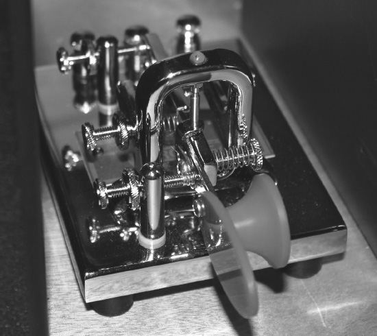
FIGURE 3-1 A paddle for sending Morse code with an electronic keyer. This model is the Vibroplex VibroKeyer Deluxe. It has existed for over half a century, and you can still buy one today.
The other type of keyer uses a keyboard. You simply type in what you want to send, and as long as you stay ahead of the output with your typing, the device will generate perfect code at whatever speed you select. These keyboard keyers first came out in the 1970s to meet the demands of high-speed CW operators who wanted to carry on conversations at 50 wpm or more. Figure 3-2 shows the keyboard keyer that I acquired around 1975, manufactured by a company called HAL Communications. That thing still works! However, most hams use computer programs nowadays to generate CW if they want to send it with a keyboard.
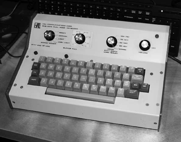
FIGURE 3-2 A keyboard for sending high-speed code, an art that enjoyed popularity in the 1970s.
Radioteletype
Radioteletype (abbreviated RTTY and sometimes pronounced “ritty”) involves the wireless exchange of printed or screen-displayed text matter. On the HF bands, hams use frequency-shift keying (FSK) to accomplish this. The mark and space frequencies differ by 170 Hz, resulting in the so-called 170-Hz shift. Before about 1970, you could often hear 850-Hz shift signals as well, but that mode has fallen from favor because it takes up more bandwidth than a ham-radio RTTY signal needs. On the VHF bands, audio tones are applied to the microphone input of an AM or FM transmitter, resulting in an emission mode known as audio-frequency-shift keying (AFSK).
Baudot Teleprinters
The oldest RTTY code is called Baudot, and allows for printing of uppercase letters of the alphabet, numerals, and common punctuation marks. A sequence of pulses called “line feed” causes the teleprinter carriage or computer display to back up and move to the next line before printing will resume.
Mechanical teleprinters, some of which remain in use today, employed either continuous-feed “roll paper” or continuous-feed “accordion fold” paper. When running at full speed, a Baudot teleprinter produced characters at a rate equivalent to 60 wpm. That’s still the standard Baudot speed for ham radio use today. Another speed specification, called baud, expresses the number of signal-state changes (from mark to space or vice versa) per second. The typical ham radio RTTY speed, equivalent to 60 wpm in plain English text, is 45.45 baud.
Teleprinters were, in effect, automatic electric typewriters. In fact, when transmitting, you’d type on a keyboard just like the one on any common electric typewriter of the day. The mechanical system wouldn’t let you pound out characters at a rate any faster than the maximum 60 wpm. Most hams, being poor typists, didn’t find that constraint troublesome. If you could type faster than 60 wpm and tried to do it on one of those machines, it would physically restrain you; you could feel the force in the keys pushing back on your fingers!
You can find quite a few hams communicating with RTTY using 45.45 baud Baudot today. They hang out in certain parts of the HF bands, mostly in the upper parts of the digital-mode segments, just “above” (in frequency) the Morse code gang. The ARRL Headquarters station W1AW still transmits official bulletins regularly using 45.45-baud Baudot. Relatively few people copy the signals on mechanical teleprinters nowadays; computers do the job quietly and without mechanical parts, ink cartridges, and paper to break down or run out.
ASCII
If you do serious work on RTTY, you’ll find Baudot rather primitive because you can’t transmit and receive lowercase letters. In addition, the Baudot non-alphanumeric symbol set is limited. Engineers invented the American Standard Code for Information Interchange (ASCII, an acronym pronounced “askee”) in the middle of the last century to address this issue. This code comprises a lot more code elements than Baudot has. In fact, ASCII contains 128 different character codes, while Baudot has only 32.
When using ASCII with FSK or AFSK for RTTY, you can work at speeds higher than 45.45 baud (60 wpm). Common speeds are 75 and 100 wpm. However, ASCII is not used very often for plain old FSK-style RTTY by radio hams. Instead, ASCII is reserved for other digital modes we’ll discuss later in this chapter. Some of those modes have the capability to go many times the speed of conventional RTTY, but some actually go slower. In any case, the allowable bandwidth is limited on the HF bands by FCC law, and that constraint places a practical maximum on the communication speed.
Station Equipment for RTTY
If you want to start working RTTY right now and you don’t want to take the vintage “teleclunker” route, you’ll need a computer, and probably also a separate interface unit. The computer, with the proper program and audio input, can read and display RTTY on your monitor right out of the box. All you need is an audio cord to connect your radio’s audio output (from the headphone jack or from an auxiliary connector on the rear panels of some radios) to the “line in” jack on your computer, along with one of the several RTTY programs available today.
If you want to get your radio to transmit RTTY, an outboard interface unit will help you do it with versatility and ease, although some computer programs claim to let you transmit all sorts of digital signals without one. I use an interface box called the RigBlaster Pro, manufactured by a company called West Mountain Radio, between my computer and my radio. I’ve never had any trouble with it after over a decade of use along with my Icom IC-746 Pro transceiver. At the time of this writing, West Mountain Radio maintains a website at
To get an idea of currently available computer programs that can read and generate AFSK tones (which will come out of your radio when you receive, and go into it when you transmit, regardless of the actual RF signal frequency), do an Internet search on the phrase “programs for RTTY” and explore the hits that you get. I use a basic program called MMTTY, which came on a CD-ROM with my digital mode interface unit, manufactured by West Mountain Radio around 2003. You can also find MMTTY on the Internet, but you’ll have to look around a bit to find the latest version. Figure 3-3 shows the full MMTTY display with the program in action. This and most other RTTY programs include graphical tuning aids to help you properly adjust your radio’s frequency.
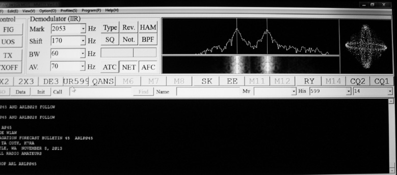
FIGURE 3-3 The MMTTY program display for Baudot includes a text display with adjustable background along with three different tuning scopes.
Normally, if you want to receive RTTY, you should set your radio to lower sideband (LSB) mode. Some radios have a special RTTY filter that can give you a narrow passband to minimize interference from signals at nearby frequencies. Tune your receiver so that the mark signal produces an audio tone of 2125 Hz and the space signal produces an audio tone of 2295 Hz, representing a 170-Hz shift. (Those particular frequencies aren’t an absolute requirement, but they’ve become the informal standard.) Some programs display the audio frequency numbers for you; with others, you’ll have to guess, and that’s where the graphical tuning aids really help.
Figure 3-4 shows a close-up of the three tuning aids in MMTTY. The display at the upper left indicates optimum tuning when the two signal peaks coincide with the vertical lines. The lower left display scrolls down with time; you should align the brightest parts of the signal with the two vertical lines above it. The right-hand display shows two ellipses that appear oriented horizontally and vertically, crossing each other as shown, when you have a signal tuned in correctly, and assuming that the signal has the proper amount of frequency shift. Any one of these three types of display will work satisfactorily for most operators.
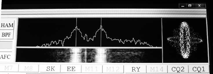
FIGURE 3-4 Closeup of the MMTTY tuning scopes. They’re intuitive; playing with the program and your radio for a few minutes will teach you all you need to know about how they work.
I recommend that you test two or three RTTY programs on your computer to find the one that agrees best with your temperament. They all have a small resource footprint, meaning that they don’t gobble up much memory space, hard drive space, or processing power on latter-day computers that typically have several gigabytes of memory, around a terabyte of available storage on the hard drive, and multiple-core processors. However, not all of these programs work to their full potential on newer operating systems, and a few of them might not work at all on some computers.
Most ham RTTY programs are written for Microsoft operating systems, notably the venerable old Windows 98 or Windows XP, so you’ll face a challenge if you’re a Mac user. However, I did locate a program called MultiMode after an Internet search, and the authors claim that it allows a Macintosh computer to send, as well as receive, RTTY and several other digital modes without a separate interface unit.
Phase-Shift Keying
Several variants of RTTY emission exist besides FSK. One of the most popular of these modes, known as phase-shift keying (PSK), conveys text by varying the phase, rather than the frequency, of the carrier wave. Whenever you change the frequency of a signal, an inherent phase shift goes along with it, and vice versa. So in effect, PSK produces the same results as FSK.
Binary PSK
In ham radio, the most popular variant of PSK splits the carrier into two opposing phases, so it’s sometimes called BPSK for binary phase-shift keying. The carrier phase remains constant during the entire length of any single bit, and might (or might not) shift by 180 degrees, or a half cycle, for the next bit. The most common BPSK mode works at 31.25 baud and goes by the full-length technical moniker BPSK31.
For hams who can type well and who adhere to common English usage in regards to capitalization and punctuation, plain text (such as what you’re reading right now) BPSK31 signals come out at 45 to 50 wpm. Of course, for slow typists, the speed comes out slower than that. And, for those folks who insist on sending their text in all uppercase (as the old Baudot code did by default), the practical speed with PSK turns out closer to 30 wpm.
Where to Find It
Most BPSK31 enthusiasts populate informally agreed-on frequency slots in the digital-mode segments of the HF ham bands. These zones are 3 kHz wide, about the same as the bandwidth of an SSB signal. Look for BPSK31 activity in the following frequency ranges:
• 160 meters: 1.838 MHz to 1.841 MHz
• 80 meters: 3.580 MHz to 3.583 MHz
• 40 meters: 7.035 MHz to 7.038 MHz and 7.070 MHz to 7.073 MHz
• 30 meters: 10.140 MHz to 10.143 MHz
• 20 meters: 14.070 MHz to 14.073 MHz
• 17 meters: 18.100 MHz to 18.103 MHz
• 15 meters: 21.070 MHz to 21.073 MHz
• 12 meters: 24.920 MHz to 24.923 MHz
• 10 meters: 28.120 MHz to 28.123 MHz
Occasionally you’ll hear a signal that’s a long way outside these zones, and people often stray slightly above or below them, especially on 40 meters and 20 meters when activity grows heavy. In any case, as a general rule, BPSK31 signals always go in the digital-only sections of the ham bands.
Programs That Do PSK
Numerous radio hams have written programs for receiving and sending PSK in its various “flavors.” All of these programs can decode and encode BPSK31. You can get some of them as downloadable freeware on the Internet. I like two in particular: DigiPan and HamScope. Both of them originated for Microsoft Windows XP, but I have run them on Windows 7 and Windows 8. My ham station computer has both of these programs installed. I use DigiPan’s excellent high-definition tuning aid to see where CW signals reside within my receiver’s passband, so I have the text screen and control bar disabled. For ordinary BPSK operation, I use HamScope because it can also decode signals in the exotic mode known as multiple-frequency-shift keying (MFSK).
DigiPan 2.0 was created by Amateur Radio operators. Figure 3-5 shows the operating screen. You can adjust the font style, font size, font color, and text background color, as well as the extent to which the text fills the screen. The lower part of the screen contains a tuning aid called a waterfall. All good PSK programs have waterfall displays, at least as an option. The name comes from the fact that the signals, which appear as bright vertical lines, move down the screen with the passage of time, so that the whole display looks like a real waterfall if you use your imagination. You tune the receiver within the passband by giving your mouse a single left click at the top of the bright colored line representing the signal you want to decode. When you want to transmit, you can hit a button marked “T/R” on a control bar at the top of the screen. (I have the control bar disabled in the rendition shown in Fig. 3-5. To display it, hit “View” and then hit “Control Bar.”)
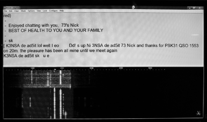
FIGURE 3-5 The DigiPan program working in BPSK31 with a waterfall tuning aid. Signals appear as bright vertical lines.
HamScope 1.56 was authored by another ham radio operator. Figure 3-6 shows the operating screen for HamScope as it receives some signals in the BPSK31 mode. You can select between a waterfall display and a spectrum display for tuning. I use the spectrum display in HamScope because it offers a clearer indication (to my eyes, anyhow) than the waterfall does in that particular program. The display shows signal amplitude versus frequency averaged over a short time interval as the upper graph, and instantaneous amplitude versus frequency as the lower graph. Signals appear as vertical “bumps” called pips. When you want to decode a signal, you move a pointer (which looks like a tall, skinny human figure between two vertical lines) to its pip, and then left-click your mouse to make a bold, vertical, dashed line move there. If you like, you can enlist the assistance of automatic frequency control (AFC) that helps the program get on the correct frequency for optimum decoding. When you want to transmit, you hit a button on the control bar that says “Rx,” and it will go over to “Tx.” To go back to receive mode, hit the “Tx” button.
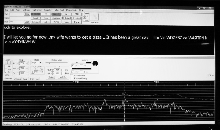
FIGURE 3-6 The HamScope program working in BPSK31 with a spectrum tuning aid. The upper trace shows a time-averaged response; the lower trace shows an instantaneous response.
As you familiarize yourself with DigiPan or HamScope or any other program that you decide on, I recommend the COEISASWH (click on everything in sight and see what happens) approach. You can try out the “Help” menu, but it might not work on all computers. In any case, you had better prepare yourself for a learning curve when you start working with communication programs like these. For example, you’ll need to select the correct COM port for your computer audio before you can get the program to work at all, and you’ll have to play around with the audio levels in order to optimize everything in transmit mode and make sure that you put out a decent signal.
When adjusting your equipment to send BPSK31, or any other digital mode, using audio tones into the microphone input of a radio, you run the risk of intermodulation distortion (IMD or “intermod”) that will produce splatter, or signal artifacts that come out near, but on either side of, your operating frequency. You can minimize IMD by adjusting the interface gain, computer audio output, and/or microphone gain controls in your radio so that the audio level remains slightly below the threshold at which your radio’s automatic level control (ALC) kicks in. Most transceivers will show you, on the front-panel display, when that happens.

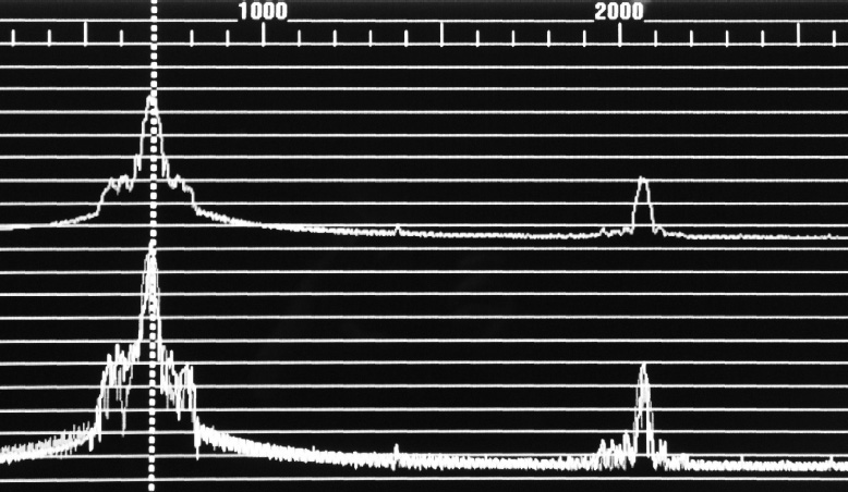
FIGURE 3-7 Harmonic distortion commonly occurs in the audio stages of radios and computers. Don’t let it get you in trouble when you transmit digital signals using audio tones at the microphone input of your radio!
Multiple-Frequency-Shift Keying
As you tune around the HF band segments in which digital signals other than CW prevail, you’ll hear all sorts of tweets and chirps and tone bursts, some of which sound rather musical, others of which sound like exotic birds or insects. After using RTTY and BPSK31 for a little while, you’ll learn to recognize those modes by the way they strike your ears. But what about some of the other signals you hear?
What Is MFSK?
One of the most interesting and promising new digital modes is multiple-frequency-shift keying (MFSK). In practice, it’s a form of FSK similar to ordinary RTTY, but instead of using two different well-defined carrier frequencies, MFSK uses several different well-defined carrier frequencies. The two primary “flavors” are MFSK16 with 16 frequencies, and MFSK8 with eight frequencies. Radio hams use MFSK16 more often. When you tune in a signal, it comes out of your speaker or headset as a rapidly fluctuating sequence of audio tones.
Error Correction
One of the outstanding features of MFSK16 is forward error correction (FEC), a form of data redundancy in which the transmitting station sends every data bit more than once. That way, the receiving station can be “pretty sure” that it got each bit correct. This process slows down the transmission speed and causes the data to arrive in spurts or bursts at the receiving end. When you tune in an MFSK signal using a program, such as HamScope that can decode it, you’ll notice this effect right away. You’ll see a few characters arrive all at once on the screen, followed by a pause, followed by a few more characters all at once, and then another pause, and so on. At full speed, a ham radio MFSK signal moves along at about 42 wpm, averaged over time.
Other Features
Another notable feature of MFSK16 is the way the signal modulation keeps going in transmit mode, even when you aren’t typing anything on the keyboard. Known as idle insertion, it keeps the receiver synchronized with the transmitter during pauses in the transmission, so that noise bursts or stray signals don’t throw the receiver off and degrade the performance of the system. And that performance can, I have heard, be spectacular indeed. Although I have not witnessed it personally, I’ve read that signals will sometimes show up on-screen even though a human operator listening to the receiver audio can’t tell that any signal exists. If that’s true, then MFSK16 might surpass CW as the mode of last resort in adverse conditions. I’ve displayed MFSK16 from W1AW bulletin transmissions under conditions so bad that I had trouble at times telling that the signal was still there.
Using MFSK16
When receiving MFSK16 signals, you have to tune them in precisely or else you’ll get no results. The first thing you’ll want to do is to make the receiving program recognize the signal boundaries at the upper and lower frequency limits. Figure 3-8 shows how this works in HamScope. The photo at A shows the program in spectrum mode, and the photo at B shows the waterfall mode. You’ll see a pair of dashed lines indicating the standard points for the MFSK16 frequency boundaries. (I prefer the spectrum mode with this program because the dashed lines extend all the way up and down the display; in the waterfall mode they don’t.) You’ll want to move the dashed lines around with your mouse until they coincide as nearly as possible with the signal boundaries. At some point, you should start to see text on the display.
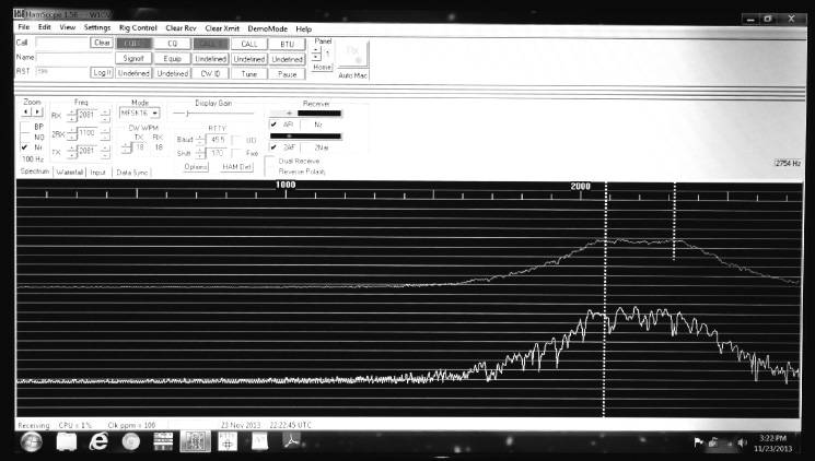
FIGURE 3-8A HamScope display of the MFSK tuning method called the spectrum mode. To tune a signal in, you adjust the positions of the dashed lines so that they coincide as closely as possible with the “edges” or “skirts” of the signal.
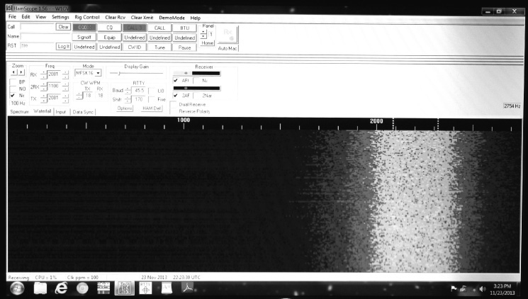
FIGURE 3-8B HamScope display of the MFSK tuning method called the waterfall mode.
The MFSK mode is sideband sensitive, so if you’ve got your radio set to receive signals in the LSB mode and the operator at the other end is sending the signal in the USB mode, you’ll have to reverse the sense or polarity of your reception. An “upside down” signal won’t “print.” In most MFSK16 programs, you can do that by either hitting a reversal button, or else switching your radio over to the opposite sideband. In HamScope, the button bears the label “Reverse Polarity.” If you use a different program, you might see it as “Rev” or “Reverse.” Just poke around until you find it!
You’ll probably have to exercise your powers of patience when tuning in MFSK16 signals. Not only can the tuning get quite critical in regards to setting the frequency, but also you can’t always easily see the signal in a graphical tuning aid display, so you end up guessing at where the dashed lines (or other tuning boundary markers) should go.
Amateur Teleprinting over Radio
In ham radio practice, the first mode to take advantage of ARQ handshaking for error correction became known as amateur teleprinting over radio (AMTOR). Obviously, all wireless text modes qualify as “teleprinting over radio,” including RTTY, PSK, and MFSK. But AMTOR differs from those other modes because it involves continuous exchanges of data in both directions, with frequent switchovers (once or twice per second), once contact has been established. A few pioneering hams started using AMTOR in the early 1980s after having adapted it from the commercial mode called simplex teleprinting over radio (SITOR). It has an outstanding advantage over RTTY, PSK, and MFSK: You can maintain almost error-free, albeit sluggish, communications even when lots of fading, interference, or noise occur, if you’re willing to take the hardware and programming steps necessary to work in the ARQ mode.
One-Way Error Correction
When a station sends a CQ (“calling anyone who wants to answer”) in search of a contact, AMTOR works pretty much like ordinary RTTY using FSK, although AMTOR employs a more sophisticated code that allows for uppercase and lowercase letters as well as numerous punctuation marks and symbols. The AMTOR code has seven bits for a total of 128 (27) possible combinations, as opposed to the 32 (25) possible combinations in the five-bit Baudot code. An AMTOR CQ sounds just about the same, when it comes from your loudspeaker or headset, as an ordinary RTTY signal does. Error correction is incorporated in the form of FEC, similar to the method used in MFSK.
Two-Way Error Correction
When a two-way contact (or QSO) is established between different stations, AMTOR switches over to the ARQ mode of error correction, which some engineers call backward error correction (BEC). The transmitting station sends three characters, and then pauses and waits for a confirmation from the receiving station. If the receiving station gives the “okay,” then the transmitting station sends the next three characters. If the receiving station says nothing or says “not okay,” then the transmitting station repeats the three characters previously sent.
When you listen to a QSO between two stations using AMTOR, assuming that you can hear them both, you’ll recognize it right away by its “tweet, tweet, tweet” sound. In many cases, one station will come in better than the other, so the “tweets” will alternate between strong and weak. Sometimes you’ll hear only one of the stations, so the “tweets” will alternate with brief periods of silence. The only problem these days is finding an AMTOR signal to check out! The mode seems to have fallen out of favor, perhaps because of the immense success and popularity of PSK31, and increasing technical interest in MFSK and WSJT modes.
How Fast Is It?
As you can imagine, the real-world speed of an AMTOR transmission depends on communications conditions between the two stations. If there’s not much interference, fading, or noise, then the signal cruises along at maximum speed because the transmitting station must send each group of three characters only once. However, if conditions are not so good, the transmitting station has to repeat some sets of characters. The worse the conditions grow, the more the sets of characters have to be repeated, and the slower, in practice, the communications get. Under poor conditions, this process makes for tedious contact, but with fewer errors than in modes, such as conventional RTTY, that don’t use ARQ. If conditions get prohibitive, then in effect the speed goes down to zero because acknowledgments never get received.
Packet Radio
A packet is a block of digital data sent from a computer at a source station to another computer at a destination station. The destination-station operator doesn’t have to directly attend to the equipment in order for a packet to be received; the computer can store it. For this reason, packet communications is a form of time-shifting communications. It’s a lot like electronic mail (e-mail) in that respect.
Networks
Wireless packet networks are getting larger, easier to access, and more sophisticated all the time. The data speed (thousands of baud) exceeds that of other popular ham radio digital modes, allowing for the transmission of fairly long messages. Packet communications is self-correcting. The destination equipment detects discrepancies in received data by means of handshaking, similar to the method used in AMTOR. In an ideal packet network, you can send a message to any destination, anywhere in the world, and have confidence that the network will automatically get it there within a few minutes or, at most, a few hours.
Amateur-Radio packet communications is called packet radio. Instead of connecting the computer to the commercial Internet by means of a cable, wireless, or satellite modem, you interface the computer with a ham radio transceiver using a terminal node controller (TNC), which acts as a special-purpose modem with built-in memory. Packet radio is, in effect, computer communications by wireless means, and in ham packet radio, that communications can take place (if desired) entirely apart from the Internet. If the utility and commercial infrastructures go down, packet radio will still work to some extent if you’re willing to use HF for long-haul links.
The Terminal Node Controller
A TNC assembles packets that are composed on, and stored by, the computer, and then converts the packets into a form suitable for transmission by radio using digital-to-analog (D/A) conversion. The TNC also takes packets from the radio receiver, and puts them in the proper format for display and/or storage on the computer; that’s analog-to-digital (A/D) conversion. If a TNC has its own memory, it can store an incoming message indefinitely, and send it out again at any time. The computer can also store the message. In effect, therefore, a well-equipped amateur packet radio station can function as a communications repeater. Because the packets themselves exist in digital form, repeaters of this sort have gotten the nickname digipeater. Each digipeater in a packet radio network constitutes a node.
A Packet-Equipped Ham Station
Figure 3-9A shows a simple ham packet radio station. The personal computer is equipped with Internet access (such as a cable, wireless, or satellite modem) as well as a TNC, so messages can be sent and received by means of conventional online services as well as with the transceiver. With this arrangement, you can receive a packet from the radio, store it in your computer, and send it to someone at a specific e-mail address on the Internet or to another ham with a packet-equipped station, either directly or through one or more digipeaters.
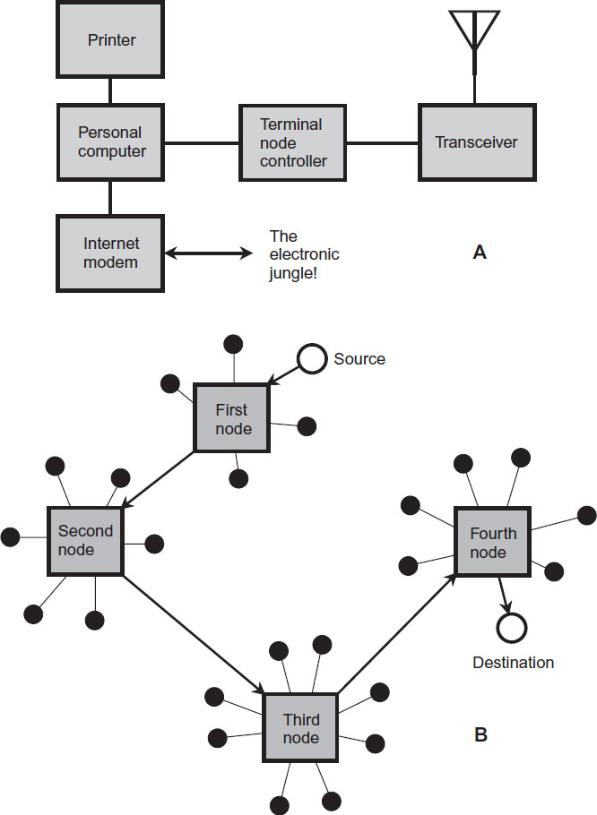
FIGURE 3-9 At A, a ham station equipped for packet radio. At B, the passage of a packet through nodes in a wireless communications circuit. Black dots represent end users.

Nodes and Links
Figure 3-9B shows a generic example of how a packet radio message gets routed. The black dots represent subscribers (end users) with packet communications capability. The four rectangles represent local nodes, which can exist at geographically diverse locations. Each local node serves several stations in its immediate vicinity by means of short-range links on the amateur VHF, UHF, and microwave bands. The nodes can be interconnected by terrestrial radio links if they’re relatively near each other. If the nodes are widely separated, satellite or HF links are used. Unfortunately, HF packet communications is rather inefficient and slow because of variable propagation conditions. Nevertheless, it can serve as an option when everything else fails.
In a packet radio network, the source station needs to know a specific address that identifies the local node of the destination station, as well as a specific address for the destination station itself, in order to send the message and ensure that it gets where it’s meant to go. The transfer then takes place automatically, in much the same way as data goes over online computer networks, except that some of the link goes over ham radio media, which by law can’t be commercialized. If you aren’t a radio ham but have occasion to “employ” a ham radio operator to get a message to a loved one in a disaster area someday, the radio ham won’t (and legally can’t) accept any remuneration for the service.
Bulletin Boards
In Internet practice, a bulletin-board system (BBS) is a “forum” for stored messages, accessible by means of a computer. A BBS lets you use a modem to connect your computer to the Internet—or to a ham packet radio network, in which case you have a packet radio bulletin-board system (abbreviated PBBS)—and leave messages for other users, just as you would do with paper and thumb tacks on an old-fashioned bulletin board. With a TNC connecting a computer to a radio transceiver, you can access numerous PBBSs. You can leave messages for, and read messages from, other hams or general Internet users at any time. You can leave messages for as long as you want, and then delete them when you want them gone from the system.
A PBBS can function even when the destination operators are not physically present to look after their stations. That’s why you’ll sometimes observe a significant delay in transferring messages. The operator of the destination station must check the PBBS before he or she can get the message. A delay might also occur if the network has difficulty routing the packets. This can happen because the network gets overloaded with too many users at a single time, or part of it gets physically compromised (by a hurricane or wildfire for example). If part of the link goes over the HF bands, the likelihood of long delays increases.
Single Sideband
By far the most popular HF mode, single sideband (SSB, also called “phone,” a throwback to the days when voice communications was called “radiotelephone”) evolved from the older, less efficient AM technology. Basically, an SSB signal is an AM signal with the carrier and one sideband removed, and then filtered so that the bandwidth is limited to a little less than 3 kHz. In most radios these days, the audio input is filtered for a passband that ranges from 300 Hz to 3 kHz, so the practical bandwidth is 2.7 kHz. Then, in addition to the audio filtering, the RF stages of the transmitter incorporate a second bandpass filter in the IF chain.
Which Sideband Should You Use?
In amateur HF activity, most hams use the lower sideband (LSB) on the bands below 10 MHz, and the upper sideband (USB) on the bands above 10 MHz. There’s no technical advantage to using either sideband on any frequency; these standards have evolved as a matter of convention.
If you have your radio set to receive USB, you’ll find it impossible to tune in an LSB signal so that you can understand what the operator says. All you’ll hear is “monkey chatter,” the result of the higher voice frequency components coming in at low frequencies and vice versa. You’ll observe the same effect if you set your radio to receive LSB and you try to bring in a USB signal.
On the VHF and UHF ham bands, a smaller proportion of the total operators use SSB than is the case on the HF bands. Above 50 MHz, most voice communications activity takes place with FM, often using repeaters that receive and retransmit signals to extend the range of communications. However, those operators who do use SSB on VHF or UHF (mainly on the 50-MHz band) almost always employ USB.
VOX or PTT?
The abbreviation PTT stands for push to talk. That’s the simplest and most common way to operate SSB. When you want to transmit, you press and hold down a button, usually a momentary-contact switch on the side of the microphone. In most radios, you can squeeze the microphone to close the switch and talk.
The acronym VOX stands for voice-operated transmission (hams often abbreviate the word “transmission” as TX or X). In SSB mode, VOX allows you to actuate your transmitter using the electrical voice impulses from a microphone or audio amplifier. It can do this with either a relay or an electronic switch.
The VOX mode eliminates the need for throwing a switch or pressing a button to change from receive mode to transmit mode. This feature can prove especially useful in mobile operation, when you need both hands for such things as operating other controls (your steering wheel, for example). You can disable the VOX and use PTT instead if you prefer that method.
In VOX operation, the transmitter is actuated within a few milliseconds after you speak into the microphone. The transmitter remains on for a short time after you stop speaking; the delay prevents your radio from “tripping out” during short pauses, a phenomenon that most people find exasperating. Radios equipped with VOX allow you to adjust the delay time between transmit and receive modes after you stop speaking.
Automatic Level Control (ALC)
In an SSB transmitter, automatic level control (ALC) prevents excessive modulation (or overmodulation) while allowing ample microphone gain. Overmodulation causes a phenomenon known as splatter, which, if not filtered out somewhere in the IF or RF chain of the transmitter, greatly increases the emitted signal bandwidth and can cause interference to stations on nearby frequencies.
Figure 3-10A shows an amplitude-versus-time graph of a fully, but properly, modulated SSB signal with a sine-wave audio input. If overmodulation occurs, peak clipping (Fig. 3-10B) can result, producing sideband elements at frequencies outside the normal passband, as shown in Fig. 3-11. That’s splatter!
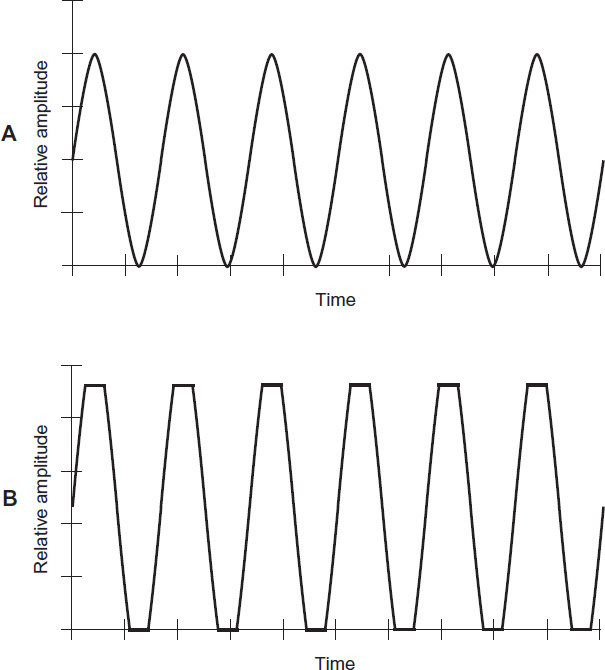
FIGURE 3-10 At A, an amplitude-versus-time graph of a fully modulated SSB signal with a sine-wave input at the microphone, free of peak clipping. At B, an amplitude-versus-time graph of an SSB signal with the same sine-wave input but suffering from peak clipping, which can produce splatter.
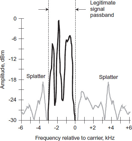
FIGURE 3-11 Here’s what splatter looks like on a spectral display of an LSB voice signal. The peak clipping produces RF emissions outside the normal SSB passband.
In a receiver, splatter sounds like a crackling noise at frequencies above and below the actual signal. Such emissions not only annoy other operators, but they can also generate disruptive interference. Splatter also violates FCC regulations because it causes an SSB signal to exceed its legally allowed bandwidth.
Speech Compression and Clipping
Speech compression is a method of increasing the average power in a voice signal, without increasing the peak power. A speech compression circuit operates in much the same way as an ALC circuit does. But speech compression carries the process farther than ordinary ALC.
While ALC is intended only to prevent overmodulation, speech compression employs additional amplification of the low-level components of a voice in an effort to get more “bang for the buck” out of the signal. The result is reduced dynamic range (difference between the loudest and the softest voice input levels), but the intelligibility can improve, especially under marginal communications conditions, because the signal carries extra “heft.” The peak power doesn’t increase compared to a signal without compression, but the average power does.
Speech compression, also called amplified automatic level control (AALC), is usually carried out in the microphone-amplifier circuits of a transmitter. But it can also be done in the RF stages. Accordingly, engineers may speak of either audio speech compression or RF speech compression, also known as envelope compression.
When speech compression is used in a transmitter, the transmitter output should be monitored with a spectrum analyzer or panoramic receiver to ascertain that splatter does not take place. Also, precautions should be taken to ensure that the average-power increase will not put too much strain on the final amplifier stage of the transmitter.
Speech clipping is an alternative method of increasing the average power of an SSB signal without increasing the peak power. Like speech compression, it can be done either in the audio or RF stages. If done properly, clipping can improve the intelligibility of an SSB signal in the same way as compression does, but clipping generates splatter as a matter of course! Whenever speech clipping is used, therefore, a high-quality, 3-kHz-wide bandpass filter must follow the clipping circuit to keep the splatter off the air.
Frequency Modulation
Radio hams use FM almost entirely on the VHF and UHF bands, that is, 6 meters and shorter wavelengths (50 MHz and above). Most operation these days takes place through repeaters, which receive signals on a certain frequency and then retransmit them on slightly different frequencies.
Bandwidth
When you frequency-modulate a carrier wave, you get sidebands above and below the carrier frequency, just as you do with AM. But there’s a difference in the way the sidebands are arranged, frequency-wise and bandwidth-wise. As you increase the deviation, additional sidebands appear, farther away from the carrier frequency than the ones that you would see with AM. The number and relative amplitudes of these sidebands is a complex mathematical function of the deviation, and also of the highest audio frequency that goes into the transmitter.
If an FM signal’s bandwidth does not exceed that of a standard AM signal having the same waveform, engineers call it narrowband FM (NBFM). For voice communications, the maximum bandwidth for NBFM is about 6 kHz, or 3 kHz above and below the carrier. Hams do most FM operation on their VHF and UHF bands in the narrowband mode.
If an FM signal has a bandwidth greater than that of a standard AM signal with the same modulating waveform, then it’s called wideband FM or WBFM. Hi-fi stereo broadcasting in the band from 88 MHz to 108 MHz provides a good example. The fidelity improves as the bandwidth increases (just as it does in any other mode), but in ham radio practice, intelligibility surpasses fidelity in importance. The FCC forbids ham radio operators from transmitting music, anyway!
Noise Immunity, Sort Of
For voice communications, FM offers better immunity to static and impulse noise than AM does because these types of noise are, in effect, amplitude-modulated. Receivers for FM can be made unresponsive to changes in signal amplitude by means of limiter circuits. Nevertheless, in practice, weak FM signals that fall far below the limiter threshold are affected by static or impulse noise because the signals aren’t strong enough to make the limiting circuits “kick in.”
Repeaters
In Amateur Radio practice, repeaters are used mostly on the VHF and UHF bands. Since about 1970, repeaters, often funded and maintained by local ham radio clubs, have revolutionized the nature of communications on these bands, especially 144 MHz (2 meters) and 440 MHz (70 centimeters).
A repeater receives a signal on a particular assigned frequency, and retransmits it at the same time, usually in the same ham band but on a different assigned frequency. A good repeater will increase the range between mobile and portable stations compared with direct, or simplex, communications. Any two transceivers that are within the repeater range can communicate with each other, even if they can’t do it on simplex.
Ideally, a repeater should be located in a high place, such as on a mountain or tall building (Fig. 3-12A). The repeater transmitter can, and often does, have much higher RF power output than a ham radio operator’s own transmitter. An omnidirectional gain antenna enhances the receiving and transmitting range of the repeater. The radius of reliable repeater coverage can exceed 100 kilometers when all these factors are optimized. Therefore, two hams using mobile equipment might have a QSO (conversation) over a distance of 200 kilometers or more. Without the repeater, the maximum communications range would be about 50 kilometers over flat terrain, and less than that over irregular terrain.
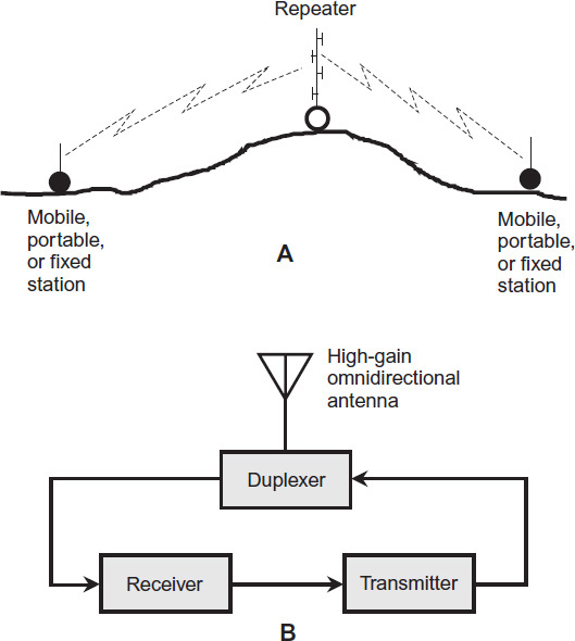
FIGURE 3-12 At A, the principle of repeater operation. At B, a simplified block diagram of a ham radio repeater.
A basic repeater includes a receiver, a transmitter, an antenna, and an isolating network called a duplexer (Fig. 3-12B). The incoming signal is picked up by the antenna and fed to the receiver. The demodulated output of the receiver goes directly into the audio input of the transmitter. The transmitter retransmits the signal at the same time, using the same antenna as the receiver.
In a repeater, the transmitter signal must differ in frequency from the received signal by at least a certain amount, called the offset or split, which varies depending on the band. Otherwise the transmitter will overload the receiver. The split generally gets larger as the repeater’s operating frequency increases. On 2 meters, 600 kHz is the most common split. On 70 centimeters, the split is usually 5.00 MHz.
Most modern transceivers have a provision for programming the split frequency in case you encounter a repeater that has a nonstandard split. If you don’t deliberately program the split in, the radio will operate with a default split representing the most commonly used value for the frequency to which the receiver is tuned.
Tone Squelching
In recent years, more and more radio clubs have equipped their repeaters with tone squelching. In this scheme, the repeater’s receiver incorporates a silencing circuit that stays closed unless an incoming signal is modulated with a tone of a certain frequency and/or duration. People who want to use the repeater must know the tone frequency and program their radios to put it out over the air, or the repeater won’t accept their signals. A repeater that uses tone squelching to regulate access is called a closed repeater. If you can access a repeater using any radio without tone squelching, then you have an open repeater.
Images and Video
Radio amateurs have been sending and receiving images, both fixed and moving, for decades. The most common ham radio image modes are television and facsimile (FAX). Television takes two forms: analog fast scan and slow scan. Most hams stick to grayscale images and videos to conserve spectrum space and get the best possible image resolution (detail). However, color images have been successfully sent and received on all the bands on which image transmission is allowed.
Fast-Scan Television
Amateur fast-scan television (FSTV) signals are just like old-fashioned analog TV broadcast signals, except that hams use less transmitter power than broadcasters did! An analog FSTV system provides 30 images, or frames, per second. Each frame has 525 lines in the screen rendition or raster. The lines run horizontally across the screen, which has a horizontal-to-vertical dimensional ratio, or aspect ratio, of 4:3.
Each line contains shades of brightness in a grayscale system, and shades of brightness and hue in a color system. In FSTV broadcasting, the image is generally sent as an AM signal, and the sound goes out as an FM signal. A standard FSTV channel takes up 6 MHz of spectrum space, or 1000 times the bandwidth of an AM voice signal! For this reason, all amateur FSTV activity takes place on the UHF bands at 70 centimeters and above. On the lower bands, FSTV signals are simply “too big.” For example, the entire 2-meter ham band is only 4 MHz wide, not even enough for one FSTV signal.
An FSTV transmitter comprises a camera, an oscillator, an amplitude modulator, and a series of amplifiers for the video signal. The audio system consists of an input device such as a microphone, an oscillator, a frequency modulator, and a feed system that couples the RF output into the video amplifier chain. It also has an antenna output, of course!
An old-fashioned analog FSTV receiver, which can be used without modification to receive ham FSTV signals, has input terminals with an impedance of either 75 ohms unbalanced or 300 ohms balanced, a tunable front end, an oscillator and mixer, a set of IF amplifiers, a video demodulator, an audio demodulator and amplifier chain, a cathode-ray tube (CRT) or “picture tube” with associated peripheral circuitry, and a speaker or headset.
In order for an FSTV picture to appear normal, the transmitter and the receiver must maintain exact synchronization. To that end, the transmitter generates pulses at the end of each line and at the end of each complete frame in the raster. These pulses get sent along with the video signal. In the receiver, the demodulator recovers these synchronizing (sync) pulses and sends them to the display. In a CRT display, such as the type used in old TV receivers, the electron beam inside the tube moves in exact synchronization with the scanning in the camera.
Figure 3-13 is a graph of a single line in an FSTV video signal, representing 1/525 of a frame. The highest signal level corresponds to the darkest shade (ideally black), and the lowest signal level corresponds to the lightest shade (ideally white). Therefore, the FSTV signal gets modulated “negatively.” This convention allows for retracing (moving from the end of one line to the beginning of the next) to synchronize between the transmitter and receiver. A well-defined, strong blanking pulse tells the receiver when to retrace, and it also shuts off the beam while the receiver display retraces by effectively turning the screen as black as it can get during that brief period of time.
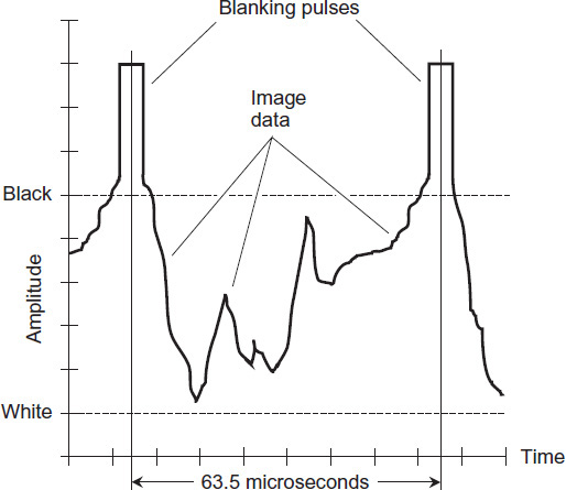
FIGURE 3-13 A single line in an analog FSTV video frame as it would appear on a lab oscilloscope.
Slow-Scan Television
A fast-scan television signal of the sort used in television broadcast takes 6 MHz of spectrum space because of the high resolution of the image, along with the rapid changes necessary to produce full-motion video. With some compromise, however, you can send a video image in a much narrower band. Slow-scan television (SSTV) accomplishes this feat in part by reducing the rate at which pictures get generated and sent. An SSTV signal needs only 3 kHz of spectrum space, equivalent to SSB in bandwidth, so SSTV is practical on HF.
A fast-scan amateur television signal has 30 complete picture frames per second. A slow-scan signal sends a maximum of one frame every 8 seconds—240 times slower, allowing a dramatic reduction in bandwidth. (Some SSTV signals go out even slower than that.) A typical SSTV signal has 120 lines per frame, compared with 525 lines per frame in FSTV. This reduction further reduces the bandwidth of SSTV.
To get an SSTV signal, you can input audio data into the microphone jack of an SSB transmitter. A tone of 1500 Hz corresponds to black; 2300 Hz gives white. Intermediate audio frequencies produce shades of gray. Synchronization signals are sent at 1200 Hz as short bursts lasting 30 milliseconds for vertical synchronization and 5 milliseconds for horizontal sync.
You can transmit SSTV images and voice transmissions at the same time by sending the pictures on one sideband and your voice on the other sideband. Then you’ll be able to carry on a continuous voice narration with fixed images every 8 seconds, something like a slide show.
If you want to use an analog television set to display SSTV images, you’ll need a scan converter. There are fewer scan lines in SSTV than in the TV receiver; the converter adjusts for this difference, yielding a picture almost as detailed (except for the lack of motion) as a TV broadcast signal under good band conditions.
An SSTV station without a computer needs a transceiver with SSB capability, a scan converter, a TV set, and a camera. Scan converters and cameras are commercially available from many ham manufacturers and dealers. Alternatively, you can use a computer, equipped with a dedicated program for encoding and decoding SSTV, along with a webcam or the computer’s built-in camera, if it has one.
Facsimile
Radio hams can send facsimile (FAX) images by means of narrowband transmissions, in a manner very much like the way it works over telephone channels. The bandwidth of a FAX signal is the same as that of an SSB signal.
Amateur FAX transmissions have resolution comparable to that of any commercial transmission. However, ham FAX is done by means of radio, often at HF, where the ionosphere introduces phase modulation and fading, and where atmospheric and humanmade noise and interference commonly occur. These factors degrade the image quality. The problem is less severe or frequent at VHF and UHF.
To send a fax from a hardcopy, you place one page, containing text and/or images, into an optical scanner that converts the hard copy into a series of binary digital pulses, that is, high and low signals (also called 1 and 0). The output of the scanner goes to a modem that converts the binary digital pulses into a signal suitable for transmission over your radio.
At the destination or receiving station, the analog signals from the telephone line or radio get converted back into digital pulses like those produced by the optical scanner at the source or transmitting station. These pulses go to a printing device or computer. A standard fax has a printer similar to a photocopier or laser printer. In fact, a rendered hardcopy fax looks like a photocopy. The image resolution of a high-quality fax is good enough to allow reproduction of most photographs.
A ham FAX transmission requires a few minutes to send. The more time that you allow for sending the image, the better the resolution you’ll get. The image goes out in lines, similar to the way in which a television raster is scanned. In ham FAX practice, 120 or 240 lines per minute (two or four lines per second) are scanned. The modulation method can be either positive or negative. In positive modulation, the instantaneous signal level is directly proportional to the brightness at any given point on the image. In negative modulation, the instantaneous signal level is inversely proportional to the brightness at any given point on the image.
Some hams have used surplus commercial FAX apparatus to build their FAX stations. If you want to do that, you’ll probably have to modify the equipment to work with your radio, a challenge to the ham who likes to tinker and perfect station equipment. Most commercial units are designed to work with AM, but they can be converted to work with FM. Some hams like to build all of their FAX equipment from scratch. Others prefer to download computer programs and let their cyber hardware take care of it all!