CHAPTER 9
![]()
Appliance Failure, Maintenance, and Repair
The principal large electrically powered appliances that are found in the home include
• Electric range
• Refrigerator
• Washing machine
• Clothes dryer
They are all used on a daily basis, and there is an ongoing possibility of malfunction or failure. The fault will be either electrical or mechanical or perhaps a combination of the two, for they may interact, and one may lead to the other. Where there are moving parts, failure becomes more likely, and then the repair can become moderately difficult, but if you approach the task in an orderly and systematic fashion, the prospect for a favorable outcome is excellent.
Isolate and Repair
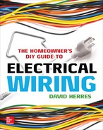
If the malfunction is purely electrical, it becomes a matter of isolating the defective component and repairing or replacing it. With a multimeter, as shown in Figure 9-1, and a modest amount of other test equipment in hand, the home crafter-electrician should not hesitate to work on this sort of equipment.

FIGURE 9-1 An inexpensive multimeter is adequate for many needs.
The most frequent mistake made by novices is that they think that they will solve the problem in 5 minutes. Because this does not usually happen, they become confused and despondent, the result being either that the appliance does not get fixed or that a professional is called in to make the repair. In this chapter, we’ll discuss some approaches to common appliance problems and see how an orderly diagnostic procedure can be applied so that success is achieved.
An Easy Starting Place
Beginning with the easiest appliance to work on, because it has few moving parts and is easy to get into, we’ll consider the electric range, shown in Figure 9-2. It is found in many homes and usually functions for years without incident until one day it fails to perform as expected.

FIGURE 9-2 An electric range—long lasting, simple to repair.
An electric range typically consists of four surface burners and, down below, an oven that is accessed through a tilt-down door. The first thing to do is to take a good look at the electric range and determine the extent of the dysfunction. An appliance may be completely dead, or it may power up to some extent but not be totally functional. If it is completely dead, despite the ominous terminology, it may be quite an easy repair.
As always in such matters, check the power supply. Most electric ranges, with the exception of some lightweight studio models, operate on 240 volts. Actually, some portion of the circuitry is designed to operate on 120 volts, so both voltages are required. They are obtained through the familiar three-wire, two-voltage supply from the entrance panel or load center. Through a double-pole breaker, two hot legs (black and red) run to the range. They are accompanied by the grounded neutral (white), which is not fused.
The voltage potential between the two ungrounded phase conductors is 240 volts, and the voltage between either one of them and the neutral is 120 volts. These are nominal voltages, and the measured amounts may differ by 3 percent or more.
The purpose of the 120-volt circuit is to operate the clock, the oven light, and any other incidental loads, as well as to power some electronic circuitry that may be present. Additionally, some models use the 120-volt supply to power some burners at a reduced level in order to obtain a lower heat.
Shock Hazards in Old Equipment
Besides the three wires, there is a fourth equipment-grounding conductor. At this point, we need to clarify an important matter. Old editions of the National Electrical Code (NEC) permitted the frame of the range, which is to say the exposed normally non-current-carrying metal parts, to be grounded by means of the neutral conductor. Frequently, 6-6-8 concentric Type SE cable, normally intended as service-entrance cable but permitted for indoor branch circuits, was used to supply power to a range, the outer braided conductive shield doing double duty as the grounded neutral and the equipment ground. Both phase conductors were 6 American Wire Gauge (AWG), and the cable incorporated a reduced 8 AWG neutral. This arrangement has not been permitted in recent Code cycles, which call for the standard three-wire plus equipment-grounding conductor setup. The dilemma arises when an old range that is on a three-wire branch circuit with no equipment ground is replaced by a newer four-wire range.
A range may be hardwired or cord-and-plug connected. A new range normally comes with a four-wire cord and plug (pigtail) that is to be field wired to the appliance.
The Wrong Way
Obviously, the best solution is to run a new four-wire branch circuit with all four wires properly terminated at both ends. What if this is not possible? Well, it is always possible, even if you have to install Wiremold raceway and/or drill through some concrete. If the three-wire cable is to be retained, let someone else do it. In installing the four-wire cord, especially on an older range, be certain that the neutral is not connected via a jumper to the frame, which would violate the principle that the grounded neutral and the equipment-grounding conductor are not to be reunited after leaving the service enclosure. Check it with your ohmmeter. Under no circumstances should the equipment-grounding conductor be floated out to a nearby radiator or isolated ground rod, nor should the equipment ground be picked up from a nearby receptacle.
Returning to our troubleshooting project, if the range appears dead, check the electrical supply at the receptacle or nearest upstream termination, at the range terminals, and, if necessary, at the breaker output terminals in the entrance panel or load center. Sometimes one leg is out because of a faulty breaker connection.
If both legs are not present at the range input terminals, it is a simple house-wiring problem, and you should have the range operational soon. If both legs are present at the range terminals but the appliance is not powering up, look for a burned wire or other visual indication that the power flow is blocked.
Finding the Schematic
If there is no visual indication of an obvious fault, the next step will be to consult the schematic. It may be pasted to the sheet metal at the back of the unit, in a plastic pouch attached to the heat shield, or near the broiler door. If you cannot find the schematic, it should be possible to download it from the manufacturer’s website, along with a parts list and service documentation.
A frequent offender is a switch. Many components are actually switches, electrically. With the range powered down, check the components that carry the main power. Then check each control circuit.
If one of the burners is not working, remove it and check it with an ohmmeter, as shown in Figure 9-3. A stovetop burner often plugs into a pair of sockets. Tip it up to clear the base, and pull it straight out. A burner that is faulty may or may not appear burned, but the ohmmeter test is definitive. The sockets where the burner plugs in can be disassembled to check the inner contacts. There is usually a short lead attached, which, in turn, may be burned or broken.
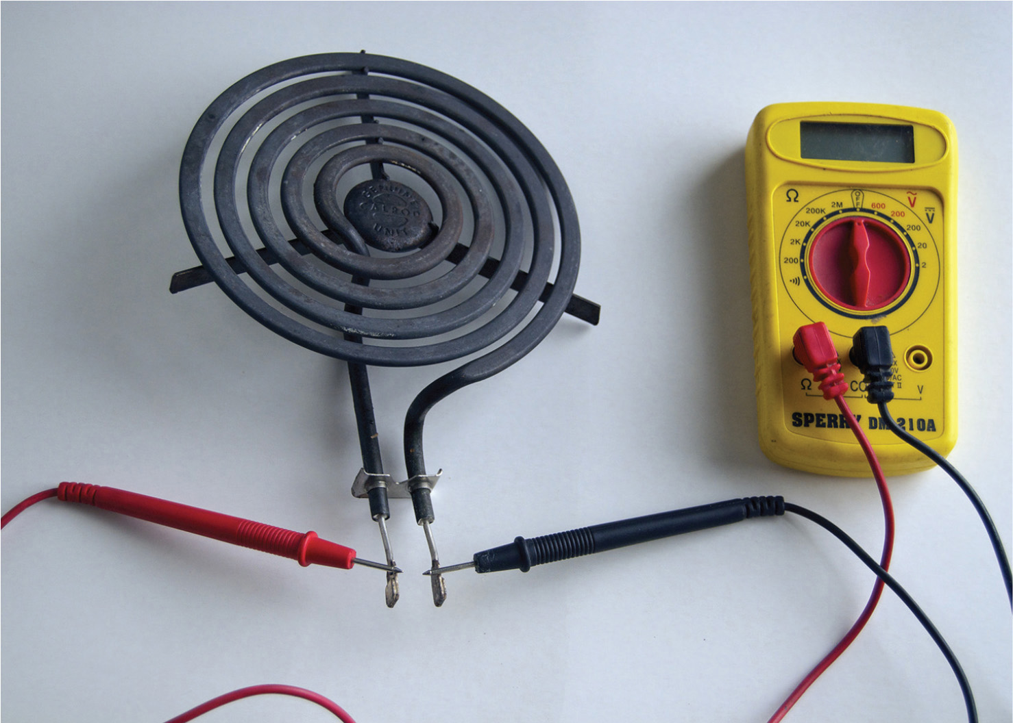
FIGURE 9-3 Checking a burner. It should read low ohms.
If a wire must be replaced, be sure to use wire with the correct ampacity with high-temperature insulation. The rating, in degrees Celsius, should be on the schematic.
The oven burners are usually bolted in place and best come out with a nut driver. They also can be tested with an ohmmeter. A bad burner will test open.
Generally, the stovetop burners have different heats, whereas the oven burners have a single heat and fluctuate on and off (based on a thermostat) to maintain the correct temperature. Most range problems are easy to fix because the circuits are simple and access is friendly to the user.
Refrigerator
We know how electricity creates heat. Current flows through a heating element, and heat is dissipated according to the expression I2R (current squared times resistance). But how can electrical energy make the temperature drop?
Consider an airtight cylinder containing a gas that is at the same temperature as the gas outside the cylinder. This gas is made up of molecules that are in constant motion. They bounce off one another like billiard balls, also rebounding off the cylinder walls. The molecular motion is related to the heat energy of the gas. At a higher temperature, the molecular motion accelerates, and greater pressure is exerted on the cylinder’s inside wall.
Heat and Pressure Are Related
If one of the end walls is pushed inward like a moving piston by an outside force, the inside volume of the cylinder decreases. Then the motion of the molecules increases. The amount of heat energy, measured in calories, stays the same, but the temperature, measured in degrees, rises. In the refrigeration process, the gas is compressed in a continuous process, changing phase so that it becomes a liquid and flowing through the circuit. Subsequently, the compressed refrigerant cools, approaching the ambient temperature outside the cylinder.
The cooling process is enhanced by forcing the refrigerant through a finned piping network that resembles an automotive radiator. Ambient air is blown through the core to reduce the excess heat. The stage where this cooling takes place is known as the condenser. The cooled refrigerant is still at a high pressure, but the temperature is close to that of the surrounding air. The high-pressure room-temperature refrigerant is allowed to expand, becoming very cold. The caloric heat energy of the refrigerant remains the same, but the temperature drops because the refrigerant is spread through a larger volume. Also, it returns to a gaseous state.
The Diffuser Valve Makes It Work
The compressed refrigerant does not remain at the same pressure and temperature throughout the entire circuit until returning to the compressor, thanks to the diffuser valve.
This device is placed in-line and marks the division between the high- and low-pressure sides of the refrigeration circuit. It is a pinhole that limits the rate of flow and hence pressure. Downstream from the diffuser valve, the refrigerant pressure is lower. As it expands, it changes back to a gas and becomes much colder.
The refrigerant is piped to a second heat exchanger that also resembles an automotive radiator. It also has a motorized fan that blows air across the metal fins that are bonded to the pipe network. This second heat exchanger is called the evaporator because it is here that the process of changing the refrigerant from liquid back to gas is completed. Air blows across the fins and is cooled, maintaining the low temperature inside the box. A thermostat, mounted on the wall inside the box, controls the compressor, causing it to turn on and off at predetermined high and low temperatures. There is a built-in differential to prevent rapid cycling.
The foregoing is a general description of the basic refrigeration process, and it applies to the household refrigerator as well as all kinds of larger refrigeration and air-conditioning systems. Breaking open the refrigerant system to add refrigerant is a job for a licensed technician. This licensing is administered on a federal level in the United States by the Environmental Protection Agency (EPA). Special tools and methods are required to ensure that refrigerant is not released to further damage our fragile ozone layer. Other repairs, where the refrigerant circuit is not opened, can be performed by the home crafter-electrician using simple tools and diagnostic methods.
Household electric refrigerators operate on the basic refrigeration principles. Because there is some variation in the details, it is necessary to consult the nameplate. Find the make and model, and then from the manufacturer’s website, download the schematic and service information.
The nameplate is usually found on the back of the refrigerator near the top. Alternative locations include at the top outside edge of the freezer door, inside the food compartment, on the inside of the vegetable crisper or meat drawer, and behind the kick plate. If the nameplate is worn or corroded so that the print is illegible, lightly sand it, and shine a trouble light across it from the side.
Refrigerator Power Supply
A 15-ampere circuit at 120 volts is sufficient to power most household refrigerators, although they are sometimes put on 20-ampere circuits, and there is nothing wrong with that. Ground-fault circuit-interrupter (GFCI) protection is generally considered incompatible with refrigeration equipment and will nuisance trip at times, possibly resulting in food spoilage. The windings in the hermetic motor-compressor are submerged in refrigerant. A small amount of moisture contamination will create an acidic mix, etching through the insulating coating on the windings. A current leakage to ground will trip out the device. GFCI protection in a residential kitchen is required for countertop receptacles only.
Check the power supply first; then check the power cord. If the refrigerator shows no sign of life including lights, a completely dead refrigerator, the power cord may have become damaged in moving the refrigerator, or it may have been pinched. Check the input terminals inside the unit. If there is voltage there, you know that the problem is internal.
Now you may have to explore different areas depending on whether the unit is dead or has partial power, as indicated by the light. If the bulb is out, test it with an ohmmeter. The center spring terminal in the refrigerator lamp socket may have lost its tension. Unplug the refrigerator, and use needle-nose pliers to pull the spring terminal out to where it belongs. If there is corrosion, use a pencil eraser to clean the metal.
Door Switch Problems
A door switch controls the light bulb. A small spring-loaded rod extends when the door is opened. See if it is stuck. Check the switch with an ohmmeter with the refrigerator powered down.
If you get the bulb to light, either the control circuitry or the compressor is faulted. Measure the voltage at the motor-compressor terminals. If the motor is not running despite voltage at the terminals, it will need to be replaced. These are sealed units, and ordinarily they cannot be repaired. A licensed refrigeration technician is needed to change the motor-compressor because it involves opening the refrigerant circuit. This repair is rarely done on a household refrigerator because it is usually more economical to buy a new unit.
If there is no voltage at the motor-compressor terminals, look for a fault in the control circuitry. Parts for most models are readily available. They may be generic or from the manufacturer. To perform the diagnosis, consult the schematic. Try a search engine or YouTube, and you will likely find tech forums that will answer specific questions or a video that will show a teardown.
Checking the Icemaker
Some refrigerators have icemakers. There will be an in-line water filter in the incoming water supply, and it may need to be changed.
All icemakers have some sort of bin switch. It controls power to the icemaker. When the bin becomes full of ice cubes, the bin switch prevents the icemaker from running so that ice cubes will not continue to be produced and overflow the bin. If the bin switch is stuck open, there will be no ice.
A thermal bin switch shuts off the icemaker’s power when the ice level rises to contact it. Try warming this sensor. It may be necessary to replace it. A mechanical bin switch is attached to a swivel. When the ice level is low, it drops down, and the icemaker is powered up. The rising ice level pushes the sensor upward, opening the switch.
A mechanical bin switch may stick in the off position. Pulling it down may get it going. If the problem recurs, adding weight by attaching a metal object such as a nut to the sensor lever may be the answer.
Washing Machine
Washers and dryers, shown in Figure 9-4, are set side by side where possible to facilitate loading wet clothes into the dryer. The doors should open outward. A dryer door usually can be reversed.
FIGURE 9-4 Washers and dryers require a little specialized knowledge to service them successfully.
The household washing machine is more of a high-maintenance item than either of the appliances we have discussed so far. This is largely due to the fact that there are more moving parts that have greater force exerted on them. There is always an electric motor, usually induction (asynchronous), as well as a transmission that allows for agitator and spin cycles. There are two electrically operated solenoid valves connected by flexible hoses to the domestic hot- and cold-water supplies. These hoses have standard hose fittings with rubber washers.
Many users, to economize, do not use the hot water. It may be shut off at the external supply valve or just not selected at the control panel. There is no pump involved for the hot- and cold-water supplies. They are pressurized by the premises water system.
An Easy Repair
The cold- and hot-water supplies both have strainers at the inlets. If the machine is observed to be filling slowly, the cause is probably a plugged strainer, especially on the cold-water side. Remove the hose, and you can feel the screen just inside the inlet. If you cannot clean it in place, pull it out with needle-nose pliers and reverse blow it out. Be careful not to pinch or puncture it.
After reattaching the hose and pressurizing the line, the joint may be found to leak. Obtain a new rubber washer, identical to the one in a garden hose, and you’re good, unless the threads have been stripped because of cross-threading or overtightening.
Sometimes the solenoid valve stops working or develops a crack, causing it to leak. This part is not very expensive, and it is easy to replace. For an economy job, if hot-water operation is not desired, it may be possible to switch the hot and cold solenoid valves. This cannot be done in some newer models that have dual solenoids built into the same body. You may, however, be able to switch the hoses and electrical terminations. Before condemning the solenoid, check the voltage at the terminals to make that sure it is getting the right signal.
The drain, unlike the cold- and hot-water supplies, has a pump driven off a V-belt. The drain line consists of a flexible hose with a J-bend at the far end so that it can be hooked onto a vertical drain line that goes into the sewer line or to a separate gray-water dry well.
If the eject pump is not working, the drum may be emptied prior to servicing by lowering the drain line so that the water runs out by gravity flow into a floor drain or is hauled away in buckets. (When the pump has failed or is not being driven, water will run freely through it.)
If the washing machine is to be subject to freezing temperatures, it will have to be drained because the pump and associated piping do not drain completely at the end of the eject cycle. For a top loader, tip the machine down so that it lies on a soft pad, and remove the hose from the pump. It is held in place by a very strong spring clamp that may be released (with difficulty) using water-pump pliers. There is a specialized hand tool that makes this task easier. Slide the clamp back along the hose, and pull the hose off the pump. It may be necessary to roll the machine a slight amount from side to side to get all the water out of the drain circuit. Be sure to reattach the hose before putting the washer back in service. The pump is usually belt driven. If it doesn’t pump, look for a broken or slipping belt.
If the motor shows no sign of life, check for voltage at its terminals. If it makes a humming sound but does not turn, the transmission may be seized or the drum obstructed. Another possibility is a bad-start capacitor, as shown in Figure 9-5.

FIGURE 9-5 The electrolytic start capacitor is a frequent offender.
If there is no voltage at the motor terminals, assuming that the 120-volt supply has been checked out, there is likely a problem in the electronics. Troubleshoot the timer using a schematic if it is available. The timer usually has spade-type electrical connectors and is easy to change, a common repair.
If the motor runs, but agitator and/or spin action is not taking place, check the belts. You may have to unbolt and electrically disconnect the motor to get the new belt(s) in place.
Most washers have door interlocks that interrupt power to the motor when the lid is lifted. This switch may fail, mechanically or electrically. Except temporarily for test purposes, never bypass the lid switch. It is there to prevent injuries, which may be severe.
Clothes Dryer
Clothes dryers are a little easier than washers to service and repair in part because airflow is more user friendly than water flow and also because the moving parts are fewer in number and less energetic. The power supply is 240 volts, with some 120-volt loading, so it is a three-wire (plus equipment ground) circuit fused at a mere 30 amps. There are electric heat elements and a single motor. It causes the drum to rotate fairly slowly so that the clothes tumble as they dry more efficiently, and it also powers the blower, which is located downstream from the drum. Consequently, the contents of the drum are not pressurized, but instead, they are exposed to slightly less than atmospheric pressure. The air is drawn past the heat elements into the drum through the tumbling clothes, then through the lint filter, and finally along the vent tube to the outside, where any remaining lint is dispersed and carried away by the breeze.
Clothes Not Drying
The biggest single problem exhibited by a clothes dryer is that the clothes do not dry well. After the timer causes the cycle to end, the clothes are found to still be damp. This is often caused by an obstruction in the airflow. Clean the lint filter, and check the outdoor shroud to see if the coarse screen, which is intended to keep small animals out, has become clogged. In more severe cases, the flexible vent tube has become plugged. It may be necessary to pull the appliance back from the wall, disconnect the vent tube, and inspect it using a flashlight. An effective remedy is to feed a shop vacuum hose in from one or both ends. The problematic thing about a kinked vent tube is the fact that you sometimes cannot see the tube without pulling the machine back from the wall, which makes the kink go away, only to reappear when the dryer is pushed back into place. As an experiment, try operating the machine away from the wall. It may be necessary to shorten the vent tube a little to prevent kinking.
Another cause of poor drying is one or more bad elements. Sometimes you can open the door of a machine that is in the drying cycle and quickly look inside before the light from the hot elements fades.
Drum Won’t Turn
If the motor is running but the drum is not turning, look for a broken or slipping belt. Typically, the belt is very long and goes around the outside of the drum. It is easily replaced.
Most dryer timers consist of a manually operated control that allows the user to select the amount of time in minutes that drying cycle will operate. More advanced models combine temperature and, in some models, humidity controls. To see how all this works together, it is necessary to consult the schematic and manufacturer’s documentation. Solid-state electronic machines introduce an additional level of complexity. If there is an alphanumeric readout with an error code, type it along with the make and model (off the nameplate) into a search engine to find tech forums that should provide an answer.
Dryers may exhibit some mechanical symptoms. They usually involve noisy operation that indicates that breakdown is imminent. Drum supports, which vary in number with different models, may wear out, causing an ever-worsening low-frequency rumbling sound.
Similar sounds are emitted if the belt breaks, causing the belt tensioner to contact the motor shaft. Another kind of noise results when a belt tensioner seizes up or the belt tension spring breaks. These are simple mechanical repairs.
On the inside of the drum are removable plastic vanes that cause the clothes to tumble. They are held in place by screws that are accessible from outside the drum. These screws will need to be tightened if a vane becomes loose and starts clattering.