CHAPTER 11
![]()
Data and Communications Networks
Data and communications networks in the home can range from simple configurations such as a peer-to-peer connection of two computers or two telephones on the same extension to far more elaborate combination Ethernet and wireless structures with many types of machines connected to each other and to the outside world through a modem. If you are getting ready to build a new home or addition, now is the time to design the network so that the cabling will go to the right places, well concealed between points of access. Before describing the mechanics of network cabling, we’ll put it in perspective by looking at some of the electronic equipment that is to be connected at both ends of each cable run.
Satellite Dish Antennas
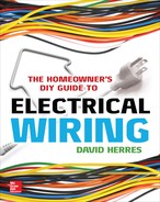
To start at an upstream input, we’ll consider TV and Internet satellite dishes, as shown in Figure 11-1. They are usually mounted on the outside wall or roof of the building or on a pole a short distance away.
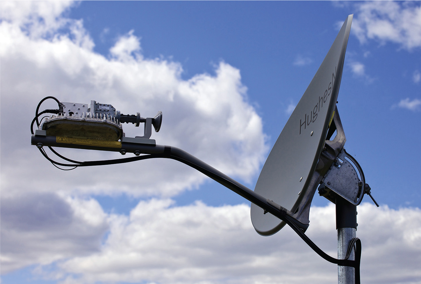
FIGURE 11-1 This satellite dish is stationary, yet it is always pointed precisely at a geocentric satellite.
It is impossible for electromagnetic radiation to pass through the Earth, so at one time, all broadcasting that went beyond line of sight was restricted to amplitude-modulated (AM) radio signals bounced off an unpredictable ionosphere or carried by a primitive cable network crisscrossing land and sea. Arthur C. Clark, the great science fiction writer, in 1945 proposed a system of geocentric communications satellites. They would revolve 22,237 miles above the Earth in circular orbit directly over the equator. To observers on the ground, the satellites would maintain fixed positions in the sky. For this reason, properly aimed satellite dish antennas on Earth could communicate with these unmanned space stations, overcoming the line-of-sight limitation. At present, there are hundreds of these geocentric satellites, permitting Internet access and cable TV in the home.
Anatomy of the System
In preparing to design a home data network, it is instructive to see how TV and Internet data move from the satellite dishes through the modem and into the home cabling system. The dish is an antenna. Because of its parabolic shape, it has the ability to reflect incoming parallel rays into a single focal point. This process results in passive amplification, the first stage in processing the signal that has been received. But because of the very high microwave frequencies, capacitive and inductive losses would deplete the signal long before it could travel the 30 feet or so to the modem inside the building.
Extremely high frequencies cannot be transmitted by ordinary cabling without great loss. However, still in the form of radiation, they can travel without substantial reduction in strength or distortion along the inside of a waveguide. This is the cylindrical or rectangular tube that you see associated with every satellite dish. The dimensions of this waveguide are based on the frequency of the signal to be conveyed, allowing it to easily pass through the waveguide, bouncing from side to side off the polished inside surfaces. The signal travels the length of the feedhorn to a pickup probe, a small antenna attached to the low-noise block (LNB), as shown in Figure 11-2, which provides further amplification and reduces the carrier to a lower frequency by beating it against a specified frequency generated by a local oscillator.

FIGURE 11-2 The low-noise block performs several functions associated with processing a satellite transmission.
Because there are semiconductors inside the LNB, a direct-current (dc) power-supply voltage is needed at the dish. Running from the modem inside the building is a length of coaxial cable that carries the power-supply voltage to the dish. This same coaxial cable carries the signal traveling in the opposite direction.
If the purpose of the dish is to provide TV reception, there is no need for transmission, so a single coaxial cable connects it to the receiver inside the building. If it is an Internet access system, two coaxial cables, joined together as a twin cable, run out to the dish. One coaxial cable is for reception, and the other is for transmission.
The home crafter-electrician should become adept at working with coaxial cable, as shown in Figure 11-3. This versatile type of cable gets its name because the outer jacket (a grounded metal sheath that serves as the return conductor), dielectric insulating layer, and inner conductive pin all share the same axis.
FIGURE 11-3 Coaxial input and output for a satellite dish modem.
It is user friendly. With a round profile and just the right stiffness, it is easy to fish through small holes and tight places. Using the right tools, you can cut, strip, and crimp on a connector in a few seconds, and a complete line of available fittings permits multiple types of installations, indoors or out.
The old die-type coax crimper made unreliable terminations. It has been replaced by a compression crimper, shown in Figure 11-4, that is a snap to use, makes watertight joints, and ends the problem of connectors that fall off later on.

FIGURE 11-4 Coaxial cable with a connector, tools including a crimper, and an assortment of fittings.
If the satellite dish is mounted on the house, secure the coax to the wall, and connect it to a grounding means, as shown in Figure 11-5, adjacent to the entry hole.

FIGURE 11-5 The grounding means is part of the antenna discharge unit.
You can drive around suburban neighborhoods and get a good sense of satellite installations in all their diversity. A lot of them are not grounded, and of those that are, many are not fully compliant with the National Electrical Code (NEC), Chapter 8, “Communications Systems.” The key concept is that satellite dish installations are to be grounded and bonded to the building electrical grounding system.
Part II of NEC Chapter 8 deals with receiving equipment, including antenna systems. A satellite dish is considered an antenna. There must be a listed antenna discharge unit, which is the grounding means. It can be outside the building or inside as near as possible to the conductors’ entry. It is not to be located near combustible material.
Grounding a Satellite Dish System
The antenna discharge unit has a grounding lug. Connect it to a 6 American Wire Gauge (AWG) bare or insulated, stranded or solid copper conductor connected to the premises grounding system, if it is no farther than 20 feet. If the distance exceeds 20 feet, a separate grounding means, usually a ground rod, is to be provided adjacent to the antenna discharge unit. In this case, the dish grounding means is still to be bonded to the premises electrical grounding system. Use 6 AWG copper, and run it in as straight a line as possible.
If it is a TV satellite dish, the coax is brought into the building and connected to auxiliary equipment provided by the dish manufacturer and then to the receiver, by which is meant not the TV itself but a cable box placed next to the TV and controlled by the user’s remote. The receiver is connected to the TV through a short length of coax or color-coded RCA cables and jacks to provide video and stereo sound.
Getting a Good Signal
The first step in designing a satellite dish system is to perform a site survey. The dish has to be mounted sufficiently high to access the microwave signal from the satellite. Because this signal cannot pass through solid objects, including hills, buildings, and trees, there must be line-of-sight access. A roof or wall mount usually works, but sometimes a pole is needed to get the dish high enough.
Usually, the homeowner subscribes to TV or Internet dish service by signing up either online or at a retail store. Installation may or may not be included free of charge depending on a large number of variables. The vendor often turns the installation over to a nearby satellite dish installer. If the homeowner wants to perform his or her own installation, a certain amount of knowhow is needed. You should be aware at the outset that an Internet access satellite dish installation is more exacting than a TV hookup, and additional steps are required in configuring the connection to the home network. For an experienced technician, the installation could take half a day, less with a good helper.
Mounting and aiming the dish are crucial. If the aiming is off by a slight amount, you might get a good signal at first, but any rain or snow will cause pixilation or a complete outage. The mounting must be absolutely solid; otherwise, a strong wind or the passage of time will throw the dish out of alignment.
Once the dish has been connected to the TV or computer, an on-screen signal-strength meter will appear. A helper, viewing the screen inside and equipped with a cell phone or yelling, can communicate with the worker who is aiming the dish. Another possibility is to take a portable TV or laptop (with a wireless connection to the modem) to where it can be viewed at the dish location. Do not think, however, that you can sweep all over the sky until you hit on the satellite. That would be like trying to hit a small target 22,237 miles away. Furthermore, you would be likely to lock onto some other satellite that would not peak out. The best procedure is to find the correct initial settings for your location, either online or from the vendor, and then use them as a starting point. Rather than using the on-screen signal-strength meter, professional signal meters that connect at the dish are more accurate and easier to use.
An Internet access satellite dish connects to the modem, shown in Figure 11-6, inside the building through two coax lines, one for transmission and one for reception. Unlike the TV satellite dish setup, the Internet access modem connects to the computer using unshielded twisted pair (UTP) cabling, making use of a communication protocol known as Ethernet. Like coax, UTP is widely used and quite easy to deploy. For the home crafter-electrician who intends to include data networking as a part of the wiring project, a knowledge of both these types of cabling is essential. The good news is that the skills necessary for working with them are easily acquired.

FIGURE 11-6 Modem for Internet access satellite dish system. Notice the two coaxial cables, one for receiving and one for transmitting, that come from the dish. A Category 5e cable feeds the modem output to an Ethernet hub, which is necessary because two computers are connected.
The Importance of Ethernet
When the modem associated with a satellite dish is connected to one or more computers, or the computers are wired to each other or to printers, the configuration is known as a local-area network (LAN). This is generally confined to a single building, but sometimes it spills over into nearby buildings under the same ownership. A larger network is known as a wide-area network (WAN), which may be spread throughout a municipal area, extend coast to coast, or cross international boundaries.
When the home crafter-electrician decides to build a LAN, Ethernet is the way to go. For initial low cost, ease of installation, and long trouble-free operation, it excels. It is not necessary for an individual who wants to wire Ethernet to understand all the details concerning the inner workings of the protocol, but some background information will be helpful.
Ethernet is based on an acronym, CSMA/CD, that stands for Carrier Sense Multiple Access Collision Detect. This is a precise description of the Ethernet process, in which each member constantly listens to determine if there is network activity. If there is no traffic, transmission may commence. If two members of the network attempt to transmit at the same time, their data streams collide, and neither transmission is successful. To prevent this from happening, both members of the network halt transmission. They wait different amounts of time and then attempt another transmission. This process enables Ethernet to overcome the principal impediment to successful network operation, which is data collision.
The Ethernet Protocol contains other elements as well. But our main interest is in a different part of the equation, which is the Ethernet medium, usually unshielded twisted pair (UTP), as shown in Figure 11-7.

FIGURE 11-7 UTP, in this case Category 5e, has four twisted pairs of conductors. The tool makes quick work of precisely stripping the jacket so that there is never a nicked wire.
Traditional electrical work is serial in nature, arranged in a daisy-chain pattern. Branch-circuit power comes from an overcurrent device in an entrance panel or load center. It goes first to a receptacle or other device, then on to the next, and so on. Running power first to a junction box and then branching out to the outlets is permitted by the NEC, but this is not the best way to do it.
For Ethernet, the preferred configuration is star topology. More cable is required to wire each branch back to the source, but in data networking, this pattern is better. There are no extra splices, which are undesirable because they disrupt the twisting of paired conductors. And twisting is essential because it counteracts inductive loss.
How Twisting of Conductors Helps
Twisting of data conductors in UTP is actually the principal strategy that permits high-speed connectivity. At one time, only teletypes and printers were connected. Now, even in the home, we expect to download graphics, music, and large video files, so high-speed connectivity is required.
Transmitter, medium, and receiver comprise a continuous chain. The slowest link limits the speed of data transmission. To achieve high-speed connectivity, we need to find the bottleneck and eliminate it. Traversing the cable, the data are made up of a stream of bits, each of which is in either of two states, on/off, true/false, or one/zero. The two states are represented by two voltages, such as +12 volts and 0 volts.
In digital transmission, the transitions between these voltage levels are abrupt, practically instantaneous, unlike the graceful sine-waves characteristic of analog signals. For this reason, a high twist rate for the conductors is needed, and this is the essence of UTP. Because digital transmission involves high frequencies, capacitive reactance and inductive reactance become limiting factors. Capacitive reactance, which is measured in ohms, becomes less at high frequencies, but because it appears in parallel with source and load, it tends to shunt out the signal, the effect increasing with frequency. Additionally, capacitive coupling of adjacent pairs makes for crosstalk and a reduced signal-to-noise ratio.
Another impediment to signal integrity is inductive reactance. Whenever current flows through a conductor, a magnetic field is set up in the space that surrounds the conductor. Where the current is alternating current (ac) or pulsating direct current (dc), energy is required to move the magnetic field. High frequency, long distance, or both conspire to make the effect more pronounced. The continuous work required to move the magnetic field reduces the strength of the signal. In contrast to capacitive reactance, inductive reactance is a series phenomenon. Both types of reactance work together to weaken the signal, and the combined effects are greater at a higher frequency.
Shielding is one way to lessen the harmful effects of capacitive coupling. One method is to install the cable inside electrical metallic tubing (EMT), which is always grounded. This strategy reduces capacitive coupling to adjacent conductors and results in a better signal-to-noise ratio. Challenges involved in high-frequency data transmission also may be met by scrupulously matching impedances so that maximum power transfer will occur. Harmful reflections take place when there is a mismatch in source and load impedances. Then the digital waveform is distorted, and the signal may become totally unreadable.
Another thing that may have to be watched in large buildings is that maximum distances must not be exceeded. Using Category 5e UTP, the maximum distance is not much over 300 feet.
As current rises or falls in a conductor, as we have noted, the magnetic field moves as well. Then current is made to flow in nearby parallel conductors. The conductors, in effect, are primaries and secondaries of a transformer. This phenomenon is known as mutual inductance. A related phenomenon is self-inductance, which occurs when current flow is induced in the original conductor. This secondary current is opposite in polarity, and it is subtracted from the primary current. The end result is that the conductor exhibits impedance to the flow of current in proportion to the frequency. Like resistance, this impedance is measured in ohms and conforms to Ohm’s law, the difference being that it is frequency dependant. Of course, it increases in magnitude with the length of the transmission line.
Wire Transposition
Nineteenth-century telephone system designers employed balanced circuits to reduce loss and extend transmission range. They were able to achieve long-distance transmission by means of wire transposition. At every third pole or so, the wires would cross and exchange places. The twist rate, about five turns per mile, along with balanced transmission, greatly improved the signal-to-noise ratio.
In the past few years, there has been a vast increase in the speed of data transmission. The first networks were only required to run teletype machines or connect computers and printers, but now everyone wants to download graphics, music, and movies. Very high-speed connectivity is expected, especially in the home.
In the twenty-first century, we see that twisted-pair technology has become dominant for telephone and data-transmission applications, and it is deployed extensively in home networking. The other widely used medium is coaxial cable. It derives its name from the fact that the inner conductor is centered within the outer grounded shield, which is also the signal-return conductor. They share a common axis.
Coax has been and still is used for antenna transmission, instrumentation, surveillance video, and other applications. It was an early Ethernet medium. The only problems with coaxial and other shielded cables are that they are a little pricey and time-consuming to install compared with UTP, such as the widely used Category 5e, which is perfect for many of our telephone and data needs.
How It Works
UTP depends for its success on balanced signal transmission. In balanced signal transmission, each of the two conductors carries a mirror image of the same signal, identical but 180 degrees out of phase. Digital information is conveyed by the differential amplitude of the two signals, which may vary from zero to some predetermined maximum value. If a pair of these conductors were run past a source of interference, such as a fluorescent ballast, motor, or an ac power line, one of the conductors, the nearer one, would acquire more noise by means of inductive coupling than the other, resulting in an unacceptable signal-to-noise ratio. By twisting the members of each pair, harmful interference is greatly reduced. First one conductor and then the other is closer to the source of noise so that each receives an equal amount. Because the balanced signal is differential, the noise that is in the data line is canceled. Balanced signal transmission by itself is not totally effective in eliminating noise, but it is necessary for the conductor twisting to be effective.
Precautions
A tighter twist rate and other design improvements in UTP have kept pace with faster data speeds. Now the focus must be on the quality of the installation. UTP is easy to install and connect at terminations, but care is needed to preserve high-speed performance. Keep these points in mind:
• Do not run UTP close to a fluorescent ballast, motor with brush-type commutation, or an ac power line. Maintain a minimum separation of 6 inches, never sharing the same hole in a framing member. Keep UTP away from uninterruptible power supplies, transformers, or any equipment that generates a magnetic field.
• Leave staples and other hardware slightly loose in securing the cable so that the conductors are not pinched.
• The twist rate must not be altered. Avoid kinks, sharp bends, and too much pulling force.
• If cable is laid out on the floor, do not allow visitors to step on it.
• If it is necessary to fish cable through hollow wall and ceiling spaces, leave extra cable so that any damaged ends can be trimmed off before termination.
It is not necessary to be familiar with all the intricacies of Ethernet Standard IEEE 802.3 to successfully build a data network for the home. The protocol is contained within and implemented by network interface cards (NICs) that are required at both ends of the cabling in order to establish the link. (These Ethernet cards are backwards compatible, but the NIC for fiberoptics is mechanically different because of the termination method.)
Optical fiber cable is definitely on the horizon, but for the present, most home networks employ UTP, specifically Category 5e, because it is well able to provide the speed and reliability needed in this setting. If in the future a decision is made to cycle over to optical fiber, the existing UTP, if it is installed in raceways, can be used as a rope to pull the new cable in place, but as mentioned previously, new NICs would be needed.
Choosing the Medium
Raceway is not an absolute requirement in most environments, but it is highly recommended as an excellent installation method. UTP cable can be fastened to any wood-finish surface. For drywall, it is best to use screw clips fastened through the sheetrock layer into the framing. An alternative is to use plastic shields sized to fit the screws and set into the drywall.
Wiremold works well where a finished appearance is desired. Where possible, conceal the cable behind wall or ceiling finish. The space above a suspended ceiling works well, but the cable is not to be laid across the panels in a way that would block access. For a retrofit, use fish tapes, chains, magnets, and other installation aids.
Though not required, a top-of-the-line installation involves pulling the UTP through EMT. This very secure metal raceway is coupled and terminated using simple setscrew fittings indoors and compression fittings outside. A conduit bender will make gentle sweeps.
EMT connectors go into enclosure knockouts. One of the advantages of a metal raceway such as EMT is that because it is grounded, there is isolation from radiofrequency (RF) radiation created by harmonics as well as complete fire protection.
If a piece of UTP is damaged in handling or doesn’t look good for any reason, don’t use it in a data network. Do not use previously installed cable. However, these discards are good for telephone extensions between jacks, where there are no high-frequency issues.
Small wire nuts or crimpable bugs are suitable for telephone work, but where UTP must be spliced in a data network, an Ethernet hub (Figure 11-8), switch, or router must be used. To emphasize, all Ethernet runs must be splice-free. Unlike coaxial cable used for video transmission, a splitter will not do. An Ethernet hub or better is needed.

FIGURE 11-8 An Ethernet hub is used where a single feed splits into two or more branches. The wire at the top is an ac power supply. UTP with RJ45 modular connectors plug into a varying number of ports.
In designing a data network for the home, we must begin by deciding what type of Category 5e to use and how to install it. Category 5e UTP cable is subdivided as follows:
• It is available in solid and stranded versions. Stranded cable is used for short patch cords that will be flexed or bent repeatedly or where there is the possibility of vibration. Otherwise, solid cable is preferred because it has better high-speed performance. The two types of cable require different connectors. Both are of the insulation-displacement type. The conductor ends are not stripped. The insulation is pierced by the conductive metal prongs inside the connectors. If the copper is stranded, it is pierced, whereas in solid conductor connections, the metal prongs slide past the conductor and press tightly against it to make the connection. For the most part, you won’t be using connectors designed for stranded UTP cable because the short patch cords are generally purchased premade.
• UTP is available for plenum, riser, and general-purpose applications. This has to do with the smoke-generation and fire-propagation characteristics of the UTP cable. (It is also applicable to coax and other types of communication cable.) The amount of current carried in an Ethernet circuit is not capable of igniting combustible material. But the insulation, once ignited by a fire that originates elsewhere, will propagate flame and generate copious amounts of thick, toxic smoke. To control this hazardous situation, it is important to use the correct cable for specified environments, which are ranked according to their sensitivity. Unfortunately, the cables having less hazardous jacket and conductor insulation properties also happen to be more expensive. Plenum-rated category cable is used in any space such as above a suspended ceiling that transports air from one part of a building to another. A riser is required where the cable comprises a vertical run that penetrates from one floor to another. General-purpose cable is for other locations, and limited-use cable is permitted in dwellings only. In all cases, the cable for a more sensitive location can be used in any less sensitive location. Thus plenum-rated UTP cable is permitted in any of the other locations. For small jobs where you are not attempting to cut the cost to an absolute minimum, you may want to keep a single carton of plenum-rated Category 5e cable and use it for everything.
• UTP is also divided into indoor and wet-location cables. The latter is required for underground use in a raceway, which is always considered a wet location because the raceway is presumed to fill with water at times.
Terminating UTP Cable
At last, we come to the heart of the matter—UTP terminations. Always run the cable first, allowing extra length, before the connectors are attached to the ends. In this way, if the end is mushroomed as it is forced through a drilled hole or around an obstruction, a few inches can be trimmed back to get a good end. Also, extra cable in the form of a loop should be left at each end in case the termination has to be remade in the future.
After the cable is in place, we are ready to attach the RJ45 connectors at both ends. First, slide on a rubber boot. This item is optional, but it improves the quality of the job. It protects the cable where it enters the connector and prevents abrasive material and moisture from degrading the connection.
UTP Category 5e cable contains four twisted pairs within a loose-fitting jacket. The Ethernet Protocol specifies that either two or four pairs are to be used depending on the version. In either of these formats, the pin-out is the same. Any unused conductors are also terminated for future use and for mechanical strength.
Using sharp scissors, trim back the jacket about 2 inches. An inexpensive data cable stripper is quick and accurate, but an electrician’s wire stripper using the 10 AWG cutter will work if you take care not to nick the insulation. Note that only the jacket is removed, not the insulation from the individual conductors.
Cut off the rip cord. Untwist the conductors back to the jacket, fan them out to make a flat plane, and arrange them in the proper order depending on which of the two configurations is being used (see below). Straighten the conductors, making them parallel, in the right order, and spaced so that they will go into the connector.
Using sharp scissors or the cutter that is part of some RJ45 crimpers, make the final cut at a right angle across all eight conductors so that they are no longer than ½ inch. If you cut them too long, the Ethernet connection will exhibit crosstalk. If you cut them too short, the signal will be weak, intermittent, or nonexistent.
Making sure that the conductors are straight, properly spaced, parallel, and in the right order, push them into the connector. You should feel them bottom out. The conductors should not buckle, fold over, or exchange places. Using the RJ45 crimper, give a good squeeze on the connector. It is transparent, so you can inspect the final product. Slide the rubber boot into place, and you are done.
As for the order of the conductors, it is necessary to realize that at both ends there are transmit and receive pins. You have to connect the transmit pins at one end to the receive pins at the other end. Sometimes you use straight-through wiring, the terminations being the same at both ends. In other situations, you employ crossover wiring. It depends on what is connected at each end. If you are going from an Ethernet hub or switch to a computer, use straight-through wiring. If you are going from a computer to another computer or from a hub to another hub, use the crossover configuration. If you make a crossover cable, mark both terminations with an X so that there will be no confusion in the future.
Ethernet Pin-Outs
RJ45 pin-outs for Ethernet connections are mandated according to the Telecommunications Industry Association (TIA) standards. Looking at a connector with the clip to the back and wire opening down, there are eight terminals numbered 1 to 8 starting at the left. For straight-through wiring, used to connect a hub to a computer, T568-B is used at both ends. (T568-A could be used at both ends, but it is customary to use T568-B at both ends for straight-through wiring.) For crossover wiring, used to connect hub to hub or computer to computer, T568-A is used at one end, and T568-B is used at the other end.
T568-A is
• Terminal 1: green/white
• Terminal 2: green
• Terminal 3: orange/white
• Terminal 4: blue
• Terminal 5: blue/white
• Terminal 6: orange
• Terminal 7: brown/white
• Terminal 8: brown
T568-B is
• Terminal 1: orange/white
• Terminal 2: orange
• Terminal 4: blue
• Terminal 5: blue/white
• Terminal 6: green
• Terminal 7: brown/white
• Terminal 8: brown
This type of termination takes a little more time than a coax termination, but after you have done a few, it will be second nature. Buy a bag of RJ45 connectors to keep on hand. Soon you will be making up these cables for neighbors and at work. Terminating Ethernet lines is the most important single skill that is needed to create a data network in the home.
USB Cables
For connecting peripheral devices to a computer, Universal Serial Bus (USB) cabling is a great advance over older methods, including serial ports, telephone-line cords, and similar expedients. Introduced in the 1990s, USB cabling is now a widely used cross-platform (Mac and PC) medium becaue of its high-speed connectivity, ease of use, and reliability. Modern computers have multiple USB ports. We have all seen the familiar logo, shown in Figure 11-9. If you have more devices than ports, just add a USB hub.

FIGURE 11-9 The ubiquitous USB logo, indicating a port that will accept a USB cable connector.
Many computer peripherals, such as keyboards and mice, have permanently attached USB cords that simply plug into any one of the computer’s USB ports. There is no need to power down or restart the machine. A grounded conductor makes contact before the data pin, so there is no risk of damage from static charge.
Besides printers, keyboards, and mice, USB cabling is used to connect joysticks, flight yokes, webcams, digital cameras, modems, speakers, telephones, TVs, external data storage devices, and network connections. If a new device is plugged into a computer or hub via USB cable, the computer’s operating system detects it, requests the driver disk, and activates it.
The two ends of a USB cord are not the same. The upstream end has an A connector with a corresponding socket at the computer. The downstream end, if it is not built into the device, has a B connector. These ends are completely different, so it is not possible to plug the cord in the wrong way.
As many as 127 devices can connect to a computer through existing USB ports or line-powered USB hubs. Besides data, USB connections can supply power to the device, up to close to 1 amp at 5 volts. For the home crafter-electrician, USB is good news. Just plug it in, and you are ready to go to work.
Before you undertake a full-scale networking project, just to gain experience and confidence, we’ll start with some simple exercises. These can be simple thought experiments, if you don’t want to expend the time and materials.
Telephone Extensions
The simplest form of communication network is a telephone line extension. You have probably done one or more of them. The least sophisticated way to do this would be to purchase extra long line cords with modular RJ11 ends and extend the line using those little couplings found in discount stores. But good telephone work involves a little more planning. Always the telephone wire should be concealed, not just stapled along a baseboard. (If the wall is concrete and there is no way to conceal the telephone wire, consider Wiremold.)
In new construction, the telephone company will run the line to an interface box mounted on the outside wall. One section of this enclosure is accessible to the user, and it contains provisions to connect at least two lines using insulation-displacement terminations. It also contains a modular socket for test purposes. The utility grounds its system at this interface box by running a bare or insulated copper wire to the intersystem bonding terminal provided as part of the electrical installation. If this piece of hardware is not in place, the utility will seek out some other available ground connection. The meter socket enclosure is a possibility.
If the electrical service consists of an underground lateral, polyvinyl chloride (PVC) raceway for the telephone service should have been installed in the same trench. If this is the case, a vertical PVC riser, connected to a 90-degree sweep, should have been left as a short above-ground stub with a pull rope inside. Telephone utility policies vary, but the usual procedure is that the utility pulls a two-pair telephone line through the customer-installed raceway and connects it at the interface. It is the owner’s task to complete the installation.
To avoid wire clutter on the outside wall, bring the two pairs through the back of the interface and through a hole in the wall into the building. The telephone company can configure these two pairs as either separate lines with different telephone numbers, two lines on the same extension, or one line with a spare. For this and all other inside telephone wiring, it is recommended that Category 5e cable be used as opposed to two-pair telephone line. The advantages are
• You already have Category 5e cable for the data network, and it saves buying separate telephone wire with an additional cutoff.
• Category 5e contains four pairs, so in every telephone line there are spare pairs that can be used later if extra lines are desired. If a nail pierces a conductor behind finished wallboard, you can swing over to an unused pair at both ends.
• Category 5e solid conductors can be stripped and coiled under a terminal screw or punched down using a special tool into an insulation-displacement terminal.
• Used or creased pieces of Category 5e that are judged to be unsuitable for data transmission can be used as telephone wire because the low audio frequencies are less demanding.
The Category 5e from the telephone interface, once it has been brought into the house, can be run to a central location where all the separate telephone lines will originate. This can be on a wall in the basement, in a utility closet, or in a suitable location of your choosing. It should not be close to ac wiring, inductive loads such as a motor, UPS, fluorescent ballast, or other source of interference. They generate harmonics, and at the very least, a faint but persistent hum may be heard on all telephone lines.
The Category 5e that has entered the house should terminate in a dedicated telephone enclusure. This can be as simple as a 4 × 4 junction box or, for more elaborate installations, a punch-down board. A small telephone cabinet with a door that opens will keep out the dust and yet allow easy access.
Category 5e conductors used in telephone lines (but not in data lines) can be joined in a variety of ways. A very primitive method that works but will be found unsatisfactory in the long run is to merely twist the stripped wires together and tape them. Any jostling will cause these joints to work lose, and if there is a great number of them, troubleshooting will become an ordeal. A far better method is to use small blue wire nuts. Strip ⅜ inch of insulation from the end of each conductor. Lay them side by side, being sure that the ends are flush. Do not twist the wires. Let the wire nut do the twisting. Turn the wire nut clockwise until a definite resistance is felt. Do not tape the wire nut. As long as the ends were flush to begin with and the proper amount of insulation was removed, this type of splice is durable and trouble-free.
The NEC does not require an enclosure for this type of low-voltage splice, but it is more professional to put it in an enclosure with a cover that is accessible and labeled. The wire nuts should be positioned with the openings down so that any moisture will drain.
The next step up for a telephone line splice is the silicone-filled bug. This is an insulation-displacement method. The Category 5e (or telephone) wires, without being stripped, are inserted into the bug so that they are felt to bottom out. A special crimper, with two stops, one to ensure correct positioning and the other to regulate the amount of compression, is used to complete the connection. Silicone is observed to ooze out of the holes around the conductors. This is the most professional way to splice telephone wires. It is quick, waterproof, and resistant to vibration. Because the wires are not stripped, there is no need to worry about copper exposed on the outside.
To emphasize, these splicing methods cannot be used for data lines. If a data line is found to be defective, it is customary to remove it and install a new cable that is free of splices. If a splice or tap has to be made in a data line, an Ethernet hub or better must be used. This presupposes an ac power source nearby, unless a battery-powered unit is to be used.
Unlike electrical branch circuits, which are ordinarily daisy-chained, individual phone jacks are best run back to the source in what is known as star topology. This is feasible because Category 5e is far less expensive that 12 AWG Romex.
Category 5e cable lends itself to premises telephone wiring. The conductors may be punched down or coiled and tightened under a terminal screw. When bringing Category 5e into a 4 × 4 metal box, remove a knockout and insert a rubber knockout blank that has a small hole drilled in it. Either that, or you can make a small X with a utility knife. The Category 5e can be brought into the enclosure using this fitting, and it will never ground out against the metal or fall out of place.
One of the benefits of Category 5e in telephone work is that there are extra spare pairs. After stripping the jacket, leave them full length, and coil them around the jacket. They will be there for future use, and they won’t add to enclosure fill. In addition, they make a strain relief for the cable where it enters the jack or enclosure.
For telephone cabling, Category 5e can be spliced to two-pair telephone wire. If you are using Category 5 in a building or addition that has existing telephone wires, they should be spliced consistently so that future circuit tracing and troubleshooting are facilitated. The color codes are different and should be matched up as shown in Table 11-1.
TABLE 11-1 Color Codes for Telephone Lines

Tools for Telephone Work
In addition to the ordinary electrician, carpentry, and mechanical tools discussed in Chapter 6, some specialized tools are needed for telephone installation, troubleshooting, and repair. All of them are not essential for a home job, and they can be acquired on an as-needed basis.
For a simple single-extension installation, you won’t need much in the way of test tools. Chances are that you will complete the hookup, and it will work fine. Only when part of a complex system is not working in a large building, especially if it is old and the cabling layout is uncertain, would specialized testing equipment be needed. If you are likely to be doing more telephone work in the future, now is the time to get equipped, starting with the less expensive and more needed test tools.
You already have the most basic test tool used in telephone work. It is a simple touch-tone phone with a modular line cord. As an accessory, wire two flexible leads with small alligator clips or wire ends into a telephone jack that has a modular socket, as shown in Figure 11-10. Then you can use your telephone as a test set to access telephone service and test for dial tone where there is no modular connection.

FIGURE 11-10 Simple homemade test accessory to go with a touch-tone telephone.
An upgrade would be a professional test set. Less expensive models sell for under $100, whereas full-featured instruments that combine data-networking capability are far costlier. The test set (butt set) is, for telephone work, the real bread and butter tool used by telephone technicians over and over in the course of a day. There is an inexpensive test light with a modular plug that indicates ringing and dial tone, but you probably won’t use it if you have either the homemade or professional test set described earlier.
The tone generator (toner) is a convenient little tool that greatly expands the capability of the test set. Connected to a telephone line, it generates a distinctive two-tone audio signal that can be heard over a test set or telephone. With it connected in place, you can test the integrity of the phone line, jack, line cord, and phone. The toner is equipped with a modular socket, short line cord, indicator light, and switch that must be turned off between uses so that the 9-volt battery will not be drained.
The wand is used along with the toner. It is a noncontact tool that picks up the audio tone when the pointed probe is brought near either member of the live pair. If there is a large mass of bundled pairs, it permits the user to quickly identify the energized conductor without need of hooking onto each pair individually.
Lacking these specialized tools, it is possible to diagnose faulty extensions by means of an electrician’s multimeter, but this method is less convenient. For example, you can take ohm readings on a pair to see if it is shorted, but to test for an open line, you would need to go to the other end of the line and short out the pair with a jumper. After taking the reading, it is necessary to go back and remove the shunt.
Telephone Installation and Repair Tools
As for telephone installation tools, besides the ordinary carpentry, mechanical, and electrician’s tool, these items are needed:
• A long, thin wood bit, ⅜ × 30 inches. Additional bit extensions, fastened with Allen-head setscrews, are helpful in some situations.
• A telephone wire stapler. This resembles a standard stapler used for hanging foil- or paper-faced fiberglass insulation, but it has a specialized head suitable for rounded telephone wire staples.
• A punch-down tool. This is used to make terminations in insulation-displacement connectors, punch-down blocks, patch panels, and the like.
Professional telephone service technicians have much more equipment, and some of it costs thousands of dollars. But the items just mentioned almost always will suffice, and where they do not, your ingenuity will create a work-around.
Diagnosing Some Common Telephone Problems
Because a telephone contains semiconductors, a constant voltage is required to provide bias. This is true even when the phone is hung up in the off state. The voltage for a phone in this dormant state is 6 volts dc. When the receiver is taken off the hook, the level rises to 50 volts dc. Ring voltage goes up to 130 volts at 50 Hz.
Power-supply voltage along with an audio or audiovideo signal is quite common in many types of communications systems. If the electronic equipment is not battery powered, has no power cord, and contains semiconductors, it is usually network powered. If this power is ac, the local equipment will have a power supply, usually including a transformer. This is true for cable TV (CATV), where the standard is 60 volts ac. This makes it possible to trace CATV lines, usually coaxial cable, both indoors and outside, using standard test equipment, as shown in Figure 11-11. If the voltage is dc, the premises equipment will not contain a transformer. In a telephone system, there is no conflict between the power-supply voltage and the signal because they are easily separated by means of an electronic filter consisting of capacitive and inductive elements.

FIGURE 11-11 CATV lines can be checked using a multimeter to detect the supply voltage. Also, a small TV or field-strength meter can be used to determine the presence and quality of the signal.
The power-supply voltage can be used for troubleshooting using a multimeter. Where it is not present, there will be no audio signal, and if it were there, it wouldn’t do any good. But it is better to use a test set to get a good idea of what is going on because this instrument will provide information about the quality of the sound and let you know if there is noise on the line.
The most frequent complaint about a phone that is not working is that there is no dial tone. This is the continuous ac hum that is generated by the phone company, indicating that there is an active connection back to the central office. Very often if there is no dial tone and no sound is heard at the receiver, it is the telephone that is at fault. There are three quick and easy ways to determine if this is the case:
• Connect a known good phone to the jack.
• Connect the phone in question to a known good jack.
• Remove the cover of the jack, and connect your test set to the terminals.
If your finding is that the phone is at fault, don’t be quick to discard it. Over 50 percent of the time, it is the line cord that has become defective. A sure sign is if the dial tone comes and goes when you wiggle the cord close to either end. Disconnect the two ends from the jack and phone, and try a new line cord. Also, sometimes a one-line cord has been plugged into the wrong socket at the jack. Perhaps at one time a separate line, now discontinued, was provided for a dial-up Internet connection, and for some reason, the line cord was unplugged and then reconnected to the wrong modular socket. If this is not the case, putting in a new line cord often clears up the problem, but be aware that a brand-new line cord could be defective. Try it on a known good phone connection.
Bad Receiver Cord
The receiver, the part of the phone that contains the earphone and microphone, is connected to the phone body by means of a receiver cord, which is a tightly coiled line that matches the color of the phone. It also has modular connectors at both ends, but they are smaller and not compatible with the line-cord modular sockets. When there is no dial tone, this cord is sometimes at fault, and it can be easily checked by substitution in the same manner as the line cord. Also, the receiver may have gone bad, and it also can be checked by substitution. A receiver from a different model phone will work electrically, but it may not sit in the cradle and hang up properly, and for most applications, you also will want the color to match.
The phone may have ac power provided by a thin power cord that plugs into a nearby wall receptacle. There will be a small in-line rectangular transformer right at the wall receptacle. If the phone has ac power, there will be a power light. The purpose of this ac power is to enable certain accessories such as an alphanumeric display and other bells and whistles. If the ac power fails due to a utility outage or tripped breaker in the house, the phone will still function without the accessories, although the power light and accessories will be out. Very often this condition is caused by the plug becoming loose because of the weight of the transformer.
If there is power at the receptacle but not at the phone, it is likely that the transformer has failed. A replacement must be the same voltage as shown on the transformer nameplate. A mistake is unlikely because different voltages have different plug configurations, which are not mutually compatible. But beware that the transformer output impedance should be an exact match. If the cord or transformer is overloaded, there could be a fire hazard. The transformer will be felt to run warm, even when the phone is not in use, and if windings inside should become shorted, it could become hot, so the area should be kept clear of combustible materials.
Can’t Dial Out?
Occasionally, a phone will have dial tone and good sound, but it will be unable to dial out. This could be the fault of the utility, and that can be determined by phone substitution. If the defect is in the phone, the keypad has likely failed. If it is an expensive desk phone with an alphanumeric readout, you may want to open it up and consider replacing the keypad. This is feasible, and for many models, repair parts are available.
If the phone, including receiver and cords, turns out to be good, unplug the line cord from the jack and listen to the signal at that point, using either a good phone plugged into the modular socket or a test set at the jack terminals. Most jacks have two pairs of terminals to accommodate a two-line phone. You can determine which pair is relevant by looking at the wiring, incoming and outgoing.
The original complaint by the user could be no dial tone, intermittent dial tone and sound with intermittent ability to call out, noise on the line, or ac hum. Frequently, the fault is in the jack. One of the fine wires can be broken, or it may have come loose at the terminal. This is a particular problem when there is more than one wire under a screw. It is usually possible to wiggle wires in the jack while listening at the receiver and locate any problem that is in that area.
A professional test set has alligator clips fitted with sharp needle-like points that will penetrate the wire insulation and contact the copper conductor. Without stripping insulation, you can check for a dial tone where the telephone line enters the jack.
A telephone will appear dead if the line is either shorted or open. If there is a solid short or both members of the pair are open, the phone will be completely silent. If one member of the pair is open and the other is intact, there may be a very faint ac hum or faint background noise. If any phone in the building is shorted out, it will pull down all the other phones, so in such a situation, it is sometimes best to unplug every phone (including credit-card readers and the like) to see if that restores service and then start plugging them in one at a time.
If there is a long stretch of telephone cable that is concealed by wall finish and tests at both ends indicate that it is at fault, the best way to proceed could be to abandon the line and run new cable. It may be acceptable to relocate the jack.
Noise on the Line
If there is noise on the line, it may be caused by a partial fault between members of a pair or a partial fault to ground of a single wire. This can be subtle and difficult to find by visual inspection. If a telephone line is buried, even in PVC conduit going to an outbuilding, that can be the source of the noise. If you disconnect both members of the pair at the near end and the noise goes away, you have located the fault. Buried telephone lines are particularly vulnerable to this sort of fault where they come out of the ground at either end.
Outdoor aerial cable is also a frequent source of noise. If the noise appears during rain or windy conditions, that is an important clue. Years ago, telephone lines were customarily run on the outside of a house stapled to the siding to penetrate the wall at individual jack locations. This old cabling can come loose over the years, and the wind will cause it to slap against the wall, damaging the insulation and eventually making for noise. The bad spot in a noisy telephone line can be difficult to locate because a very small nick in the insulation can cause the problem. An ac hum can be caused by a telephone line that is located close to a power line or nonlinear (inductive) load. Opening circuit breakers individually can be helpful in locating the source.