
Co-Generation by Ethanol Fuel
Hideo Kameyama
Abstract
Steam reforming of ethanol using plate-type alumite catalysts was performed at atmospheric pressure in the temperature range of 300–600°C under space velocity of 50,000 h−1 with the objective of developing a high-performance proton exchange membrane fuel cell (PEMFC) systems. Alumite catalyst, which is prepared by anodic oxidation of aluminum plate, is advantageous for endothermic steam reforming reactions because of its excellent thermal conductivity. The method to increase durability of the alumite catalysts by preventing carbon formation was studied. The addition of Pt to Ni2Ce2 catalyst leads to satisfactory results in daily start and stop (DSS) tests with 20 cycles, and the conversion of ethanol is maintained at 100% with no observed depletion of the catalyst.
Keywords
Bioethanol fuel; ethanol steam reforming; hydrogen production; fuel cells; co-generation; alumite catalysts; Ni and Ce catalysts; fixed-bed reactor; ethanol water solution
Chapter Outline
11.1. Fuel Cell: Innovative Technology for Generating Power and Heat
11.1.2. Domestic Fuel Cells: Polymer Electrolyte Membrane Fuel Cells (PEMFCs)
11.1.3. Commercialization Requirements for the Reformer
11.1 Fuel Cell: Innovative Technology for Generating Power and Heat
11.1.1 What is a Fuel Cell?
The fuel cell converts fuel and air directly into energy through quiet, efficient, solid-state electrochemical reactions. It generates power more efficiently than internal combustion engines (ICEs) because it converts chemical energy directly into electrical current rather than via an inefficient mechanical intermediate phase. When loaded partially, fuel cells can be operated at maximum efficiency whereas most ICE generators are very ineffective, and the efficiency of fuel cells is largely unaffected by cell size. In addition, the modular design allows fuel cells to be stacked with capacities to match the specific output power needed.
The simple nature of their design and operation makes fuel cells highly reliable. If pure hydrogen is used as the input fuel, the outputs are electricity, heat, and harmless water vapor.
11.1.2 Domestic Fuel Cells: Polymer Electrolyte Membrane Fuel Cells (PEMFCs)
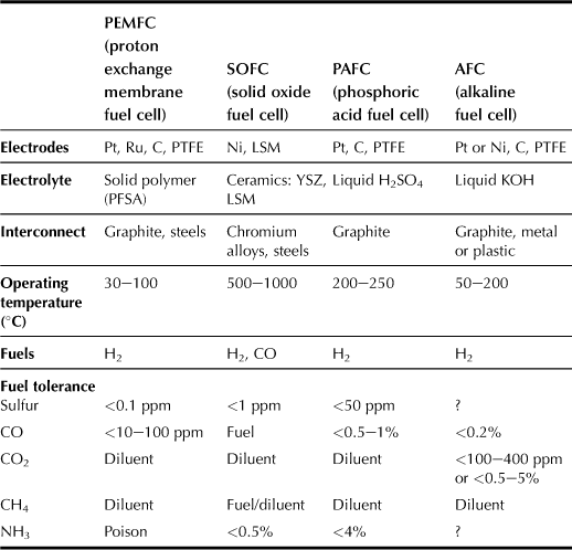
There are more than a dozen distinct fuel cell technologies currently developed by academia and industries, as shown in Table 11.1; however, only a select few are suitable for domestic micro-CHP (combined heat and power) applications. The fuel cell stack must have at least the potential of being low cost in production and having a long operating lifetime under suboptimal conditions, particularly with regard to impurities in the hydrogen fuel. There are also concerns about the safety and practicality of using pressurized hydrogen vessels in fuel cells in addition to cost-effectiveness because of the high initial and operating costs.
The PEMFC type of cell is suitable for stationary and mobile applications. The high power density of the PEMFC enables a compact design, thus allowing reduced volume and weight as compared with other alternatives. The PEMFC is operated with hydrogen and air as the inputs; the hydrogen is derived from natural gas in an upstream process known as reforming. As in a gas-fired boiler, the fuel cell heating equipment requires a gas supply pipe, combustion ventilation, and a flue pipe. PEM cells reach a constant operating temperature of approx. 90°C in only a few minutes and the heat generated can be utilized for central heating and domestic hot water (DHW) via a heat exchanger.
Domestic CHP systems based on PEMFCs have undergone intense research and commercial development over the last decade. There are at least a dozen major companies actively pursuing this market, and products have been deployed in large-scale field trials throughout Japan, South Korea, and Germany.
11.1.3 Commercialization Requirements for the Reformer
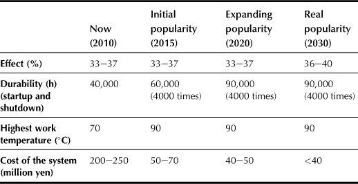
Although domestic fuel cells have been commercialized to some extent in Japan since 2005, more than 40,000 pieces of PEMFC domestic systems were sold in 2006. Reformer durability has already been confirmed to be 40,000 h (startup and shutdown, 4000 times). Nevertheless, some effort should be made to improve the performance and reduce the cost of PEMFC systems in order to meet the expected popularity of domestic fuel cells in Japan and worldwide, as shown in Table 11.2.
The minimum requirements of future PEMFC systems should include low cost, long durability and reliability, and quick startup.
a Low Cost
There is considerable competition between domestic fuel cells and traditional cost-effective energy facilities. Present fuel cells cost as much as 3 million yen because they are made manually. The fuel cell commercialization conference of Japan (FCCJ) predicted that mass production of fuel cells with 100,000 or more sets would greatly lower the production cost. It has been reported that fuel cells would be applied extensively in the urban regions of the USA if the cost of fuel cells could be reduced to the same level as that of traditional energy.
b Long Durability and Reliability
To reach the 2020 final goal a fuel processor should suffer no degradation in its normal performance for 10 years, or it should be operated to exceed 90,000 hours with more than 4000 startup and shutdown cycles without changing any catalysts, including that for desulferizer.
c Quick Startup
For residential fuel cell utilization, the startup time presents one of the many problems that affect the performance of fuel cells. Until now, the startup time of a domestic fuel cell system has been reported to be more than 50 min, and the reformer plays an important role in reducing the startup time.
11.2 Hydrogen Production Through Ethanol Steam Reforming
11.2.1 Introduction
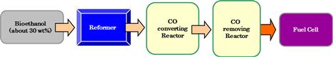
Within the past few decades, hydrogen has been considered as the least polluting fuel that has the potential to be used in internal combustion engines or fuel cells for electricity generation. Natural gas is still the main source of hydrogen due to its abundance. However, developing alternative methods or using renewable sources to produce hydrogen is of great importance based on economic and environmental considerations. In this context, a low concentration of about 30% bioethanol, which has been derived from biomass, is used to produce hydrogen through the ethanol steam reforming reaction (Figure 11.1).
Nickel-impregnated alumina is suggested as the most suitable metal catalyst for ethanol steam reforming because of its high activity and low cost. However, the main problem associated with using Ni catalysts is that the catalyst is easy to deactivate by sintering and carbon deposition or coking. With these concerns, the objective of the present research is to study the effect of adding Ce on Ni catalysts to inhibit sintering and coking.
The steam reforming of ethanol can be represented as:
![]() (11.1)
(11.1)
This research is unique in that it uses an alumite catalyst, which was patented by Kameyama (1996) with superior heat transfer as well as flexibility in shape and structure. This catalyst is supported by an aluminum-clad-based material made of nickel–chromium alloy with super pure aluminum compressed on both surfaces of the alloy. Laboratory studies verified that the catalyst surface temperature reaches 800°C in a few seconds by passing electricity through the base metal (Tran et al., 2004), and this property helps to solve the problem of long startup times. Results of many other studies have suggested Ni as the most suitable metal for ethanol steam reforming using metals with the following order of performance: Rh > Ni, Co > Pt >> Cu.
Although γ-Al2O3-supported Rh shows the best performance (Cavallaro, 2000; Cavallaro et al., 2003), Ni has been studied further because of its low cost, availability, and industrial applications (Haryanto et al., 2005); it has been proven to be the most suitable metal for ethanol steam reforming. The main by-products over the Ni/γ-Al2O3 catalyst are CH4, CO and C2H4, and C2H4 is formed through the dehydration of ethanol over the acid sites of alumite supports (Breen et al., 2002; Fierro et al., 2005):
![]() (11.2)
(11.2)
In order to suppress the acidity of alumite supports, silica is coated over anodized aluminum plates, and this method has also been applied to particle-type catalysts (Zhang et al., 2009). As a result, the formation of C2H4 is reduced remarkably with increasing selectivity of the ethanol steam reforming reaction.
11.2.2 Experimental
a Catalyst Preparation
Al-clad plates were anodized in 4 wt% oxalic acid solution with an electric current density of 65 A m−2 at 20°C for 6 hours to form porous alumina films (ca. 100 μm thick) on the outside surface. The anodized plates were rinsed, air dried, and then subject to pore widening treatment (PWT) by immersing the plate in an aqueous solution of oxalic acid for 2 hours. The plate was later rinsed with deionized water, dried, and calcinated at 350°C for 1 hour in open air. Subsequently, hot water treatment (HWT) of the calcinated plate in deionized water at 80°C was performed for 2 hours. Finally, γ-alumina films were formed by calcinating the plates in air at 500°C for 3 hours.
A 4 wt% colloidal silica solution (pH 1) was prepared by adding oxalic acid to commercial colloidal silica sol (SI50, Catalyst & Chemicals Ind. Co., LTD). An anodized aluminum plate was immersed in the sol solution at 15°C for 20 hours. Then, the plate was rinsed with deionized water, dried, and calcinated at 400°C in air for 3 hours. The resulting silica-coated support was labeled SiAl.
The catalysts were prepared by using the impregnation method. The adherence of Ni on alumina-clad plates was carried out by dipping the plate in hot Ni solution, Ni(NO3)2·6H2O (pH 10), with the solution temperature varied from 25 to 40°C for 1 hour, 3 hours, and 5 hours. After the catalysts were dried, the plate was calcinated at 400°C for 3 hours in air. On completion of impregnation, the resulting catalyst was labeled NiSiAl.
The amount of metal impregnated on the alumina-clad plates was measured using atomic adsorption spectrometry (AA-680, Shimadzu Corp.). The surface area of the catalysts was analyzed using a nitrogen adsorption method (BET) with an SA3100 Surface Area and Pore Size Analyzer. The surface of the catalysts after activity tests and durability tests was examined using scanning electron microscopy (SEM).
b Activity Tests
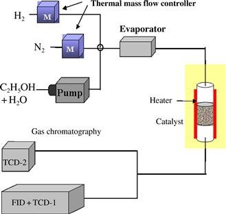
The system used to conduct this research is shown schematically in Figure 11.2. The ethanol steam reforming reaction was carried out in a fixed-bed flow reactor at atmospheric pressure. The plate-type catalysts were cut into smaller pieces (3 × 3 mm), mixed with 10 g of quartz sand, and packed in a quartz tube (i.d. = 10 mm, L = 333 mm). Before the activity test, the catalyst was reduced in a 10% H2/N2 mixture (10 mL min−1 H2 and 90 mL min−1 N2) at 500°C for 3 hours. After the reduction treatment, the catalyst was exposed to a stream of N2 flowing at 45 mL min−1 for 1 hour in order to remove the remaining H2 from the reactor. The reaction temperature was set between 450 and 600°C at atmospheric pressure. A solution of ethanol and water in a 1:6 ratio was pre-mixed and then fed into an evaporator (170°C) using an injection pump at a flow rate of 25 μL min−1. Then, the vaporized reactants were mixed with inert N2 at a flow rate of 25 mL min−1 regulated by using a mass flow controller. The steam-reformed gases collected at the reactor outlet were analyzed online using a gas chromatograph equipped with two thermal conductivity detectors (TCDs) and a flame ionized detector (FID).
The ethanol conversion rate CEtOH (%) and product selectivity Si (dimensionless) were calculated using:
![]() (11.3)
(11.3)
![]() (11.4)
(11.4)
where FEtOH,in and FEtOH,out are the inlet and outlet ethanol flow rates (mol s−1) respectively; Xi is the flow rate, which is expressed as the number of moles formed per mole of ethanol consumed, calculated by multiplying the product i (mol s−1) and selectivity Si for product compound i.
c Reaction Tests
In order to evaluate the effective quantity of Ni impregnated on the supporting plate, the quantity of catalyst impregnated was measured using an inductively coupled plasma (ICP) spectrometer. The results can be used to calculate the amount of active catalyst due to Ni impregnation on the plate. The catalyst prepared by impregnating the plate for 3 hours in the 30°C solution was found to produce the largest amount of H2 (approximately 2.7 mol per mol of ethanol) with less CO and CH4 as compared with the results obtained using the catalysts prepared under other conditions. Accordingly, at these conditions, i.e. 30°C solution temperature and 3 h calcinating time, the resulting catalyst has the largest specific surface area that allows the greatest contact between ethanol and catalyst, so that the ethanol steam reforming reaction is significantly enhanced to speed up the production of hydrogen gas.
The NiSiAl catalyst obtained by immersing the plate in 30°C solution for 3 h was further subject to durability tests. The results show that at low space velocity (SV), ethanol conversion is 100% with no apparent degradation of the catalyst observed after 50 hours of operation (Figure 11.3).
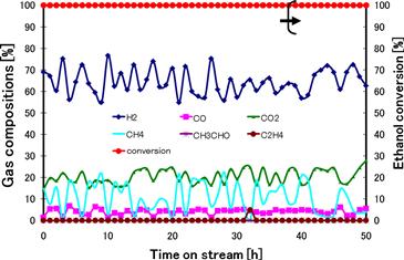
FIGURE 11.3 Relationship between gas-phase composition and ethanol conversion in durability tests at 550°C (SV = 32,000 h−1, S/C = 3).
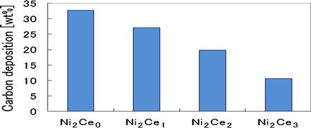
Figure 11.4 shows that a longer cerium impregnation time leads to an increasing amount of cerium on the catalyst with a reduced amount of carbon deposition. This observation indicates that the presence of cerium inhibits carbon formation. Additionally, results of durability tests show that the Ni2Ce2 catalyst usage time of 85 hours is the longest. The major depletion of Ni2Ce3 was found to be associated with the weak NiAl2O4 inner layer that causes quicker growth of nickel particles on the surface catalyst in a process known as “sintering”.
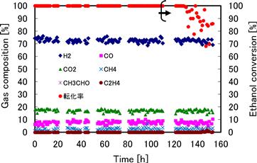
Durability tests using different levels of Ni and Ce show that Ce2Ni2 yields the longest useful time of 146 hours and the highest H2 selectivity of 72.5% due to less carbon formation (about 13.9%) (Figure 11.5).
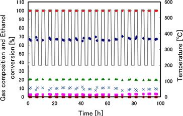
The addition of Pt to Ni2Ce2 catalyst leads to good results in DSS tests (Figure 11.6) with 20 startup and shutdown cycles, and the conversion of ethanol is always 100% with almost no depletion of catalyst observed.
References
1. Breen JP, Burch R, Coleman HM. Metal-catalysed steam reforming of ethanol in the production of hydrogen for fuel cell applications. Applied Catalysis B: Environmental. 2002;39(1):65–74.
2. Cavallaro S. Ethanol steam reforming on Rh/Al2O3 catalysts. Energy Fuels. 2000;14:6.
3. Cavallaro S, Chiodo V, Vita A, Freni S. Hydrogen production by auto-thermal reforming of ethanol on Rh/Al2O3 catalyst. Journal of Power Sources. 2003;123(1):10–16.
4. Fierro V, Akdim O, Provendier H, Mirodatos C. Ethanol oxidative steam reforming over Ni-based catalysts. Journal of Power Sources. 2005;145(2):659–666.
5. Haryanto A, Fernando S, Murali N, Adhikari S. Current status of hydrogen production techniques by previous steam reforming of ethanol: A review. Energy Fuels. 2005;19:2098–2106.
6. Kameyama H. Production method of thermal conductive catalyst. 1996; Japanese Patent No. 2,528,701.
7. Tran TP, Koyama S, Zhang Q, Sakurai M, Kameyama H. Developing a new electrically heated catalyst supported by anodized alumina layers with high heat resistance. Proceedings of the 10th APPChE Congress 2004; 1G-05, Kitakyushu, Japan.
8. Zhang L, Li W, Liu J, Guo C, Wang Y, Zhang J. Steam reforming of ethanol over Al2O3·SiO2-supported Ni–La catalysts. Fuel. 2009;88(3):511–518.