
Chapter 2. LightWave Layout
Along with Modeler, which we met in the previous chapter, LightWave 10 includes another application called Layout. Layout is where all of your hard work in Modeler pays off. In Layout, you apply textures to models; assemble scenes, complete with lighting and motion; and see the final animated results.
Just about everything in Layout can be animated, from textures to lights to cameras to (of course) objects. There are plenty of tools for you to harness; in fact, many people spend more time in Layout than they do in Modeler. This chapter guides you through a tour of the LightWave 3D Layout interface and its workflow, panels, and possibilities. You’ll learn about these topics:
• LightWave Layout interface navigation
• Simple motions
• Viewports
• New cameras
• Surfacing enhancements
• Render Globals basics
Understanding Layout
3D animation is about geometry and movement. Modeler is where you create 3D geometry, and Layout is where you put things in motion. LightWave’s animation program is appropriately referred to as Layout, because that’s where you lay out your scene. A scene consists of 3D models, lights, and cameras. Think of Layout as your stage. The 3D models you build in Modeler are your actors. You are the director. Oh, and if you haven’t figured it out yet, you’re also the gaffer, the lighting coordinator, and the production designer. Keep this in mind as you learn about navigating the Layout interface.
LightWave Layout Interface
When you first start up Layout, you see a large, empty workspace. This workspace is a three-dimensional space, rather than a flat grid as in most other programs. The view you’re looking through is a Perspective view—sort of a bird’s-eye view of your virtual set. After all, Layout is your virtual television studio, and there is a camera and a light already in place for you. Figure 2.1 shows the Layout interface upon startup.
Figure 2.1. The LightWave v10 Layout interface.
This view is the default, and there is always one light and one camera. The interface will look familiar, because it resembles LightWave Modeler in its organization and workflow.
To understand how the LightWave 3D world works, consider this: LightWave Layout is a big 3D space. When you’re working in Layout, you’re inside a big invisible sphere, and everything you do in that sphere can cause reactions in various ways with everything else, such as reflections, shadows, and even dynamics such as gravity.
Across the top of the interface are tabbed menus, each containing key tools for object editing, animating different items, compositing, and more. Before you learn about the different menus, take a look at the bottom of the Layout interface. Here, you’ll find your timeline.
The Timeline
Animation is all about timing. It’s about telling items such as lights, cameras, objects, or even textures to occupy a specific point in space at a specific time. Figure 2.2 shows the LightWave Layout timeline.
Figure 2.2. The LightWave Layout timeline.
![]()
By default, Layout measures time in frames rather than seconds or minutes. This is because 3D animation, and even 2D animation, is a frame-by-frame process. Although the computer automatically interpolates motions, it’s still up to you to create the “key” frames. A keyframe is nothing more than a marker in time. At the left side of the timeline, the value is 0, representing the first frame of the animation.
Note
Just because the front of the timeline defaults to 0, you are not locked into this value. You can start an animation at frame 6 or frame 40. You can also start an animation before 0 by entering a negative value. You would do this for certain animations that need a head start, for example. Let’s say your object needs to already be in motion by the time your viewers see it. If it starts at frame 0 and then ramps up to speed, you could start the animation at the point when it’s in full motion. Similarly, you could keyframe the motion before frame 0, and then when your animation starts at 0, the item is already in full motion. It’s all about control!
At the right side of the timeline is the ending frame number, which defaults to 60. Because LightWave defaults to the National Television System Committee (NTSC) video standard, 60 frames is 2 seconds, at a 30 frames per second rate. You can change this easily by pressing o (that’s the letter o) and opening the General Options panel. Here, you can change the Frames Per Second setting to anything you like. Later in this chapter, you’ll learn about all of LightWave Layout’s preferences.
The last frame of your animation can be changed just like the first frame. Most likely, many of your animations will go well beyond 60 frames, or 2 seconds. To change your current animation’s overall time, it’s just a matter of changing one value:
- Double-click the end frame window, which should read 60 by default. You can also just click and drag over the number.
- Enter a new value—for example, 250—and press the Enter key (Windows) or the Return key (Mac).
After you enter the value, you’ll see that the timeline looks a little different—this one’s busier because it’s now displaying keys for 250 frames instead of 60. If you need more frames for your animation, just change that value. Now, with all of that being said, you don’t have to be animating to use Layout! Thousands of users just render still images in LightWave for illustrations, compositing with other programs such as Photoshop, or simply creative art.
Selecting Items
You’ll see that beneath the timeline on the left are four interesting buttons labeled Objects, Bones, Lights, and Cameras. Above the buttons is a drop-down list called Item. When an object is loaded and the Objects button is selected, you’ll see the selected item here. You can also choose different items with this list, as well as bones, lights, and cameras. To the right of the Item list is a tiny button. If you click this, you’ll be presented with Layout’s Current Item selector. Figure 2.3 shows the item selection.
Figure 2.3. The item selection buttons allow you to choose which type of item you want to work with.
![]()
The Current Item selector will be your friend in complex scenes because it allows you to easily organize your items, especially when you’re using numerous objects in your scene. You’ll employ this feature later in the book.
Here’s your goal: Do not be confused by the buttons. Think about what you’re doing before you click. Too often, animators click the mouse, press the spacebar, or press the Esc key until something happens. Usually, something does happen, but not what they intended. Do yourself a favor and think about your actions just as you do in Modeler. Select an item, turn on a tool, use it, and turn off the tool. Think about the process. Then, by paying attention to the buttons at the bottom of the interface, you’ll know whether you are working with Layout’s objects, bones, lights, or cameras. After you’ve selected an item category, simply choose the Current Item from the drop-down list. Then pick a tool, such as Move, and have at it.
Of course, there’s more to animation than point, click, move—so much more! What’s great about LightWave’s vast toolset is that some things, such as the timeline, stay the same no matter what you’re doing. Take a look at the bottom right. Those VCR-like buttons you see are your playback buttons (Figure 2.4). Don’t confuse these with a final animation or real-time reference. These give you a pretty good idea of how your animation will play back.
Figure 2.4. The playback controls in LightWave v10 Layout.

Note
Never judge your animation entirely by the Layout playback buttons. This applies to motions, timing, shadows, textures, and so on. Always reserve judgment until the animation has been properly rendered out.
Keyframes
The best way to understand timing is to work with it every day, all day. Timing is truly the hidden art of animation. Without it, nothing works. Sure, you can make pretty images, print ads, and the like. But if you’re putting anything in motion, the timing needs to be dead on. It needs to “work.” With that said, follow this next simple tutorial to set up some keyframes of your own, and see how LightWave interpolates motion.
Exercise 2.1. Creating Keyframes
- Open LightWave Layout and make sure that nothing is in the scene. The scene is like your current project, so if you’ve loaded any objects, or sample scenes, be sure to save your work and then choose Clear Scene from the File drop-down menu (or press Shift+N).
- With a nice new default blank scene, all you’re going to do is animate the camera. Click Cameras at the bottom of the Layout interface, as shown in Figure 2.5.
Figure 2.5. Tell LightWave Layout that you want to work with cameras by selecting the Cameras button at the bottom of Layout.

- Because there is only one camera in the scene, it is automatically selected and highlighted after you choose to use cameras. If you had multiple cameras in the scene, you would select which camera you want from the Current Item drop-down list, just above the Cameras button.
Note
To add multiple cameras to a scene, go to the Items tab at the top of Layout; then from the tools on the left side of the interface, choose Add > Camera. You can name this camera anything you like. Multiple cameras are great for scenes in which you need to show your client different views. Rather than always moving the camera, it’s better to switch between multiple cameras.
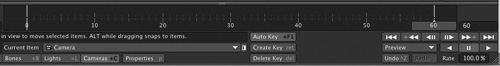
- Make sure that the Auto Key button, beneath the timeline, is on.
Layout’s Auto Key function provides a great way to get started with keyframing. When activated, it creates a keyframe to mark the position and rotation of an object, camera, or light any time you move it within a scene. As your animations get more sophisticated, you won’t always want this turned on, but it’s great for blocking out a basic scene.
- You can grab the slider in the timeline to make sure it’s at frame 0, all the way to the left. This is the start of your animation.
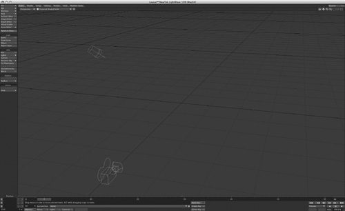
- Make sure the camera is still selected (it should be highlighted in yellow) and press t. This calls up the Move tool from the Modify tab. Move the camera slightly to test.
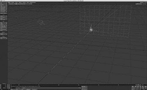
- Drag the timeline slider down to frame 60, and then click into the Layout and move the camera to a new position (Figure 2.6).
Figure 2.6. When the Auto Key button beneath the timeline is active, moving the frame slider automatically creates a new keyframe for the camera.
- Click the Rewind button at the bottom right of the Layout, beneath the timeline, as shown in Figure 2.7. This quickly jumps your timeline slider back to 0.
Figure 2.7. Click the Rewind button at the bottom right of Layout to set the timeline back to 0.

Note
A good way to keep track of your keyframes is to simply look at the timeline. When a keyframe is created, LightWave puts a small yellow dash at that point in time, like a marker. If you’re wondering how many keyframes you’ve created, look to see how many markers are in the timeline.
- Press the Play button in the timeline, and you’ll see your camera move from its 0 keyframe position to its 60 keyframe position.
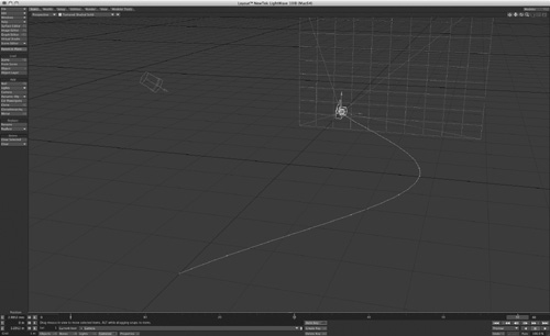
Layout calculates frames 1 – 59, and you might notice that after a keyframe at 60 is created (automatically with Auto Key), a motion path appears. That’s the white line you see connecting the camera’s first- and last-frame positions. LightWave has interpolated the motion of the frames in between. If you do not see the motion path, press d to open the Display Options panel and, under the OpenGL tab, make sure Show Motion Paths is selected. Of course, this motion path is just a straight line. So, try what is suggested in this next step.
- Move your timeline slider to frame 30. Then move the camera in some way, perhaps off to the side. You should see the motion path now curve, to accept the new keyframe. LightWave interactively updates the motion path, as shown in Figure 2.8.
Figure 2.8. With the Auto Key button on, moving the camera at any frame will automatically create a keyframe.
This example shows keyframing in the simplest form. Throughout this book, you’ll be creating more advanced keyframing—and more precise keyframing. The Auto Key button you turned on to automatically create keyframes is on by default in LightWave; but as helpful as it is, it can be quite destructive too. There are times when you should use it—for example, when tweaking character animation. Other times, you shouldn’t use it—for example, when doing precise mechanical animations. You’ll see how this use (or non-use) of Auto Key plays a part in your keyframing actions throughout the book.
Note
A quick way to jump to specific keyframes without dragging the timeline slider is to press f, which calls up the Go To Frame requester. Enter a value and press the Enter key, and your timeline slider jumps to the keyframe.
The Dope Track
There’s a hidden feature in the Layout timeline that you may or may not have found. If you move your mouse just above the timeline, right in the center, a small arrow will appear. When it does, click the bar that separates the Layout view and the timeline. You’ll see an additional timeline pop up, as shown in Figure 2.9.
Figure 2.9. Just above the timeline in Layout, you can click to open the Dope Track.
![]()
This is the Dope Track, which offers additional control over your keyframes. See, it’s all about control—the more you have, the better!
A Dope Track is a short or mini version of a dope sheet. What’s a dope sheet, you ask? It is a page that outlines all of your keyframes, motions, and timing. LightWave has its own Dope Sheet feature, which we’ll get to later in this chapter. For now, the Dope Track is a simplified version of the Dope Sheet that offers you enhanced control over your keyframes. You’ll use this during animation tutorials later in this book.
Exercise 2.2. Working with the Dope Track
To get an idea of how the Dope Track works, do the following:
- Click the top center of the timeline to pop open the Dope Track.
- You should still have your three-keyframe animation in Layout from the previous exercise, and you can use that. This scene is nothing more than one camera with three keyframes applied at 0, 30, and 60.
- You’ll see what looks like a second timeline appear above the first timeline, as in Figure 2.10.
Figure 2.10. When the Dope Track is opened, you’ll see an additional timeline above the standard timeline.
- With just three keyframes applied to the camera, you can see their representations in the Dope Track.
- If you right-click one of the keyframes in the Dope Track, you get a list of commands available to you, as in Figure 2.11.
Figure 2.11. Right-click one of the keyframes in the Dope Track, and you are greeted by a list of tools.
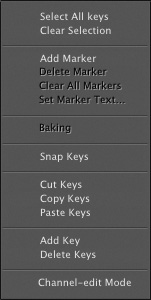
Some of these commands are ghosted with such a simple scene. However, as you build more complex animations you’ll find these tools very useful. Here are some tips to demonstrate the power of the Dope Track:
• The Dope Track shows keyframes for objects based on their individual X, Y, and Z axes, as opposed to those of the overall scene. If you create a keyframe for an object when its axes are aligned with those of the main scene and then use the Rotation tool to change the object’s heading, pitch, or bank, the keyframe you made will still be there but you’ll no longer see it in the Dope Track. That’s because the object’s relative axes will be different from those of the scene.
• The Dope Track enables you to adjust objects’ X, Y, and Z positions independently, for any given keyframe.
• In the Dope Track, the left mouse button selects keyframes.
• Hold down the Alt key and click-drag in the Dope Track to select a range of frames called a local zone. In this zone, you can bake keyframes for Move and Rotate operations. Baking is the process of converting frames interpolated by LightWave into actual keyframes. Holding down both the Alt and Shift keys sets a zone, allowing you to bake a keyframe for all objects in the scene.
Note
Mac users: Remember to Control-click to simulate right-mouse-button functions. Hey, did you go out and get a two-button mouse yet?
• If you hold the Alt key and click-drag to select a range of keyframes in the Dope Track, you can make copies of those keyframes while leaving the originals untouched.
• To delete a zone you might have created with the previous step, hold down the Control and Alt keys and drag.
• You can grab the arrows on either end of a zone to make it longer or shorter. Or, grab in the center to move a zone.
• You can snap keyframes in the Dope Track. LightWave’s General Options (press o in Layout) allow you to turn on a feature called fractional keyframes. With this feature enabled, you can snap the selected keyframe to the closest whole keyframe, such as 1, 2, or 5. A fractional keyframe is in between a whole keyframe, such as 1.3 or 2.7.
Note
Don’t worry about all of the details of the Dope Track right now. Review the information here, and then when it’s time to animate later in the book, you’ll see this section in action.
• A really cool feature of the Dope Track is support for copying and pasting keyframes. When you paste copied keyframes in the Dope Track, their placement is determined by the slider in the timeline: The first pasted frame is inserted at the slider position.
Layout Viewports
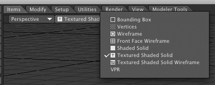
Like Modeler, Layout has multiple viewports. Look at Figure 2.12. Here you can see the viewport controls at the top of the Layout window, as you did in Modeler. Figure 2.13 shows the viewing options available for each viewport you’re working in, such as Light View or Camera View. Figure 2.14 shows the viewport render-styles pull-down, which allows you to view objects in Layout as bounding-box or wireframe forms or as solids, even with textures applied.
Figure 2.12. The default Perspective view in Modeler can be changed to any other viewport style from the drop-down menu at the top of the interface.
![]()
Figure 2.13. Click the list at the top of the Layout viewport to change to a different view.
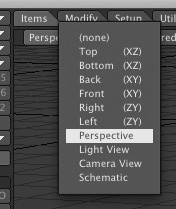
Figure 2.14. You can also choose how the objects in the viewport will be drawn.
VPR
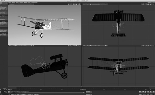
You’ll find yourself changing these views often, depending on the project at hand. Just to the right of the viewport styles drop-down at the top of the frame are additional view options such as Bone X-Ray mode. This mode enables you to see any bones applied to an object, even if the object is solid—hence the X-Ray title. There is a great new feature in LightWave 10 called VPR, or virtual preview render. Choose this view from the viewport render-styles drop-down and you’ll be instantly presented with a quick preview render of your scene. Figure 2.15 shows the VPR turned on with a scene, showing the textured airplane, lighting, shadows, and more. This is not a render, and you can work in Layout with this view, which we’ll do within the project chapters in this book.
Figure 2.15. Additional view options are available directly to the right of the viewport render-styles drop-down, at the top of LightWave Layout, such as VPR for quick interactive preview renders.

Multiple Viewports
You might be one of the select few who can work in multiple viewports while animating. If you’re not sure whether that’s your style, press F3 and you’ll see a quad view just like LightWave Modeler (Figure 2.16 on the next page).
Figure 2.16. Pressing the F3 key cycles you through LightWave Layout’s available viewport arrangements.
But wait, there’s more! Press F3 again, and again. You cycle through all of LightWave Layout’s available viewport arrangements. You can press F4 to go back. Let’s say you have a quad view in Layout set, as shown in Figure 2.16. You can set any view to any style you want—for example, you can make two views a Perspective view, one view a Top view, and the other a Camera view. Many animators like to make the Layout viewports match those of Modeler. However, you might find that working in large single views, one at a time, is quite useful.
Note
A great way to work in Layout is to employ your numeric keypad or use the number keys across the top of your keyboard. Press 1 to jump to the Back view looking down the Z-axis; press 2 for the Top view looking down the Y-axis. As you can guess, pressing 3 takes you to the Right view looking down the X-axis. Press 4 to get to a Perspective view, 5 for a Light view, and 6 to switch to a Camera view. Do this as you work, and you’ll be flipping back and forth between views without thinking about it.
Viewport Movement Control
To the top right of any Layout viewport are the viewport movement controls, just as you found in Modeler (Figure 2.17).
Figure 2.17. At the upper-right side of the Layout interface are the viewport movement controls. Click, hold the mouse button down, and drag the mouse to use them.
![]()
It’s important to note that you cannot use these controls all the time, in every view. Their availability varies depending on which view you’re working in. In Perspective view, the default viewport, these tools are all available. The five buttons are as follows:
• Center Current Item. This first button (starting from the left) stays on when clicked. Click it again to turn it off. It keeps the currently selected item—be it a camera, a light, or an object—centered at all times.
• Move. The Move button enables you to move your view around in the Perspective, Top, Side, and Back/Front viewports.
• Rotate. Click, hold, and drag to rotate your viewport in the Perspective view only.
• Zoom. The Zoom viewport tool is useful for all views except Light view and Camera view.
• Expand. The Expand view control is great to quickly maximize any viewport. For example, let’s say you’re using LightWave Layout with a quad viewport style. Click this button in any viewport to maximize it to full screen. Click it again to return to your quad view.
You’ll also find two new icons to the right of the Expand icon. When using VPR mode in Layout, you can click the camera icon to take a history snapshot of your view. This enables you to step back to a previously positioned view. The last icon takes you to VPR settings for resolution settings.
Use these viewport controls to take a proper look at your scene. They can help you stay aware of what’s going on, and controls like the Center Current Item button can help you quickly find an item you’ve misplaced in the scene: Click the Center Current Item button, select the missing item from the Selected Item list (see Figure 2.3), and the lost item will instantly jump into view. Zoom out slightly, and you can see where it is in relation to the rest of your scene.
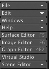
Menus and Tabs
Across the top of the Layout interface are seven tabs. As in Modeler, each tab reveals a menu of tools. When you click one of these tabs (Figure 2.18), the toolset on the left side of the interface changes accordingly.
Figure 2.18. The LightWave Layout tab set, across the top of the interface.
![]()
It’s important to note that the nine buttons at the top left of Layout (starting with the File drop-down) always appear, no matter what tab you’ve selected. These are key tools and commands you’ll use throughout LightWave, in both Modeler and Layout (Figure 2.19).
Figure 2.19. The nine buttons at the top left of LightWave Layout always appear, no matter what tab or menu you’re working in.
Note
Remember that we’re using the default LightWave tabs and menus throughout this book. Although you can change the menus to look like anything you want, the default setup keeps these nine tool buttons at the top left of LightWave Layout.
File Menu
Let’s talk about the first of these buttons: the File drop-down menu. When we say drop-down menu (or just drop-down), we’re talking about a button that has a small downward-pointing arrow. Click this button and you’ll find additional tools (Figure 2.20). Note that you do not need to click the arrow to expand the menu; just click anywhere on the button.
Figure 2.20. The File drop-down menu always appears at the top left of the Layout interface.
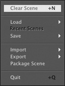
The File drop-down menu allows you to load and save scenes and use the new Save Scene Increment feature. Using this feature adds 001, 002, and so on to the end of your scene name each time you save. You can also export scenes through LightWave’s Content Manager.
Note
Pressing Control+S (Windows or Mac) on your keyboard tells LightWave to Save Scene As, whereas pressing Shift+S automatically saves a scene in increments.
Clear Scene
As the name implies, you can select Clear Scene, or press Shift+N, to clear your scene. After you perform this command, all that is left is a light and a camera. Be warned: You will not have an opportunity to save after you do this, and LightWave does not inform you that data might be lost. It asks you if you’re sure you want to clear the scene, but that’s it. So, save often!
Additionally, simply loading a new scene overrides your current scene. Therefore, using Clear Scene before you use Load Scene is a wasted step.
Load
The Load submenu in the File drop-down allows you to load scenes, load recent scenes, and load an item from a scene, which is a cool feature. You can also load objects and revert the current scene to its previously saved state.
The Load Items from Scene command in the Load submenu is especially handy for character animation. It allows you to load one scene into your current scene. For example, let’s say you create a cool-looking giraffe and set up a workable bone structure for it. Of course, you’ve saved that scene so that you can work with it later. Then, you build a huge safari scene with textures, landscapes, and lighting. Now all you have to do is use Load Items from Scene and choose the giraffe scene. The giraffe and all of its motions and bones will be imported into your existing scene.
This allows you to set up scenes on their own for both speed and productivity, but use them together for final results.
Import
This submenu provides access to LightWave add-on modules called plug-ins, which can be used to convert models and animations created in other programs. LightWave ships with just one such plug-in, Mocap_BVH_Setup, which lets you apply BioVision motion-capture data to your animations.
Export
Certain third-party applications still work very well with LightWave. However, LightWave’s core structure changed with version 6 in the year 2000, and many scenes were no longer compatible with third-party applications. Because of this, NewTek has added the ability to export your scene to LightWave version 5.6 with the Export command, which is also found under the File drop-down menu. And you can export files in VRML (Virtual Reality Markup Language) and Shockwave 3D formats, used for displaying 3D objects on the Web. You can also export a list of your scenes’ images, either for later reference or for sharing scene information.
Content Manager
LightWave’s Content Manager is extremely handy for backing up your scenes and sending them to coworkers or clients. You see, LightWave’s scene file consists of objects or 3D models you create in Modeler. The objects in your scene hold surfacing data, whereas the scene file itself holds motion data. These data files can sometimes be located in various folders around your hard drive. The Content Manager gathers all of the files associated with the current scene and copies them to a directory you specify.
Edit Menu
The Edit drop-down menu (Figure 2.21) is home to quite a few useful tools that enable you to edit menu and keyboard layouts, change window configurations, and even choose your content directory. The main features you’ll use in this drop-down list are the Edit Keyboard Shortcuts and Edit Menu Layout commands.
Figure 2.21. The Edit drop-down menu gives you access to key tools like Edit Menu Layout and Edit Keyboard Shortcuts.
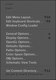
Undo and Redo
In most circumstances, you’ll use Control+Z to undo and the z key by itself to redo within LightWave. However, if you want, you can use toolset buttons to do so; they are found in the Edit drop-down list. Remember that you can set unlimited undos in LightWave Layout by pressing o for General Options.
There are a few warnings to note about using undo. First, too many undos can kill your system resources! Also, remember that undos don’t apply to everything—that is, if you accidentally turn off a texture editor layer on your surface, there’s no going back. However, if you create some bad keyframes, undo is an easy way to set them up again.
Edit Keyboard Shortcuts
Everyone likes things customized to their liking, right? LightWave 3D gives you this freedom by allowing you to assign keyboard equivalents to commands throughout the program. This next exercise shows you how to use these Edit features. Figure 2.22 shows the Edit Keyboard Shortcuts selection.
Figure 2.22. The Edit Keyboard Shortcuts panel enables you to rearrange existing keyboard shortcuts as well as create new ones.

Note
You can see any existing keyboard shortcut right on the Layout button. Any keyboard shortcut you apply will become visible on the buttons as a helpful reminder.
Exercise 2.3. Editing Keyboard Shortcuts
- Click the Edit drop-down menu and choose the Edit Keyboard Shortcuts command, or press Alt+F9 (Option+F9 on the Mac).
- A panel appears where you can choose any of LightWave’s tools and apply your own keyboard shortcut (see Figure 2.22).
- On the left side of the panel are the various commands Layout offers. On the right are keyboard shortcut listings. Scroll down the left side and select the Rendering listing. Click it to expand.
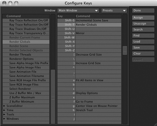
- Within the Rendering commands, you find Render Globals, LightWave’s global control panel. Select it, as shown in Figure 2.23.
Figure 2.23. It’s easy to select various commands from the categories. Here, the Render Globals command is selected.
- Scroll down the right column to choose a keyboard equivalent to assign the Render Globals command to, perhaps Shift+T.
- Select the Shift+T keyboard shortcut in the window, and on the right, click the Assign button, as shown in Figure 2.24. Click the Save button to keep your changes.
Figure 2.24. Assigning keyboard shortcuts is easy. Just pick a command, pick a key, and click Assign.
- Assign more keys to your liking, saving each as you go, and click Done.
You can always go back to LightWave’s default keyboard shortcuts by choosing the appropriate preset in the Configure Keys panel. Just click and select from the Presets drop-down at the top right of the panel. You can also set up keyboard shortcuts for the Graph Editor by choosing the option from the Window drop-down.
Note
Be sure to use the Save button within the Configure Keys panel to save your keyboard setups. Should you choose to select the default preset, your changes will be gone forever.
Another thing to remember is that you can apply these keyboard shortcuts in LightWave’s Modeler in the same way. Just select the Edit drop-down in Modeler and repeat the preceding steps.
Edit Menu Layout
Changing keyboard equivalents is great, no question. But if you want to go one step better and really make LightWave your own, try editing the menus!
Exercise 2.4. Editing Menus
- From the Edit drop-down list, select Edit Menu Layout or press Alt+F10 (Option+F10 on a Mac). You are greeted with a panel that looks very similar to the Configure Keys panel from the previous exercise (Figure 2.25).
Figure 2.25. The Configure Menus panel, chosen from the Edit drop-down list’s Edit Menu Layout command.
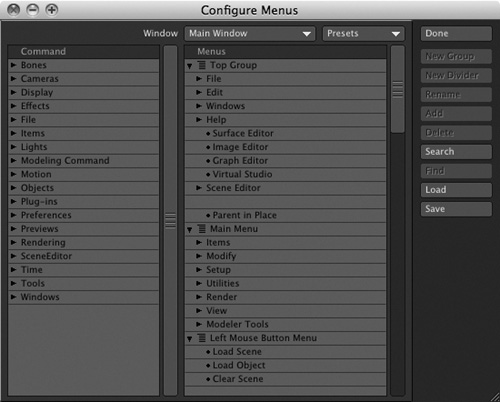
- You’ll use the panel the way you did when you edited keyboard shortcuts. Most tools are already out on the interface, but this panel is great for moving buttons, adding new menus, or creating buttons for your third-party plug-ins. Select the Parent in Place listing from the Menus column on the right, as shown in Figure 2.26. This determines the location of your new button; it will appear just beneath the Parent in Place button in the Top Group set of toolset buttons.
Figure 2.26. You can select and edit any existing menu in the Configure Menus panel.

- To the left of the panel, select the Rendering category. Expand it, and select Render Current Frame. This option will be dimmed because it’s already assigned to the F9 key and has a button, but you can still create another button for it. Once it’s selected, click the Add button at the right of the panel and you’ll see the command added to the LightWave interface. Figure 2.27 shows the new Render Frame tool button, just below the Parent in Place tool.
Figure 2.27. Adding a custom interface button is as easy as the click of a button.
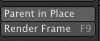
By adding the Render Current Frame command to the Top Group toolset, you’ve assigned it to every tab, so it will always be visible within Layout. If you’d created this button within the Main Menu listings, it would apply only to the selected tab. You can select various tools from the command window on the left and select your new group. Then, click the Add button. You’ve now added buttons for commands in your own custom group. Feel free to select your new group and choose the Rename button to customize it. You can also drag entries up or down in the Menus column to reorder buttons within toolsets.
You should know a few things about using these configuration panels. When a command is dimmed, that means it’s already assigned. However, that does not mean that you can’t assign it again. Also, if you ever dislike the menus you’ve created, you can always choose Default from the Presets drop-down menu in the panel. To follow along with the rest of the book, go ahead and choose the default presets.
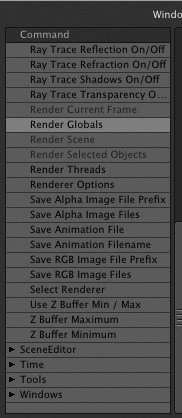
Windows Menu
Beneath the Edit menu drop-down list is the Windows menu (Figure 2.28). Here, you can access various windows or panels throughout LightWave. These windows are controls for Motion Options, including access to LightWave’s nonlinear animation controller; Backdrop Options; Compositing Options; and the Image Processing tab.
Figure 2.28. The Windows drop-down menu gives you access to many key panels throughout LightWave Layout.
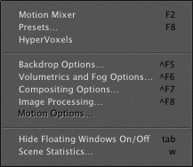
You’ll be employing all of these windows throughout this book’s tutorials. Note the keyboard shortcuts to the right of the listings for quicker access.
Help Menu
LightWave’s Help menu (Figure 2.29) can be found directly in Layout all the time. This is helpful (pun intended) for accessing LightWave’s Web-based help system.
Figure 2.29. The LightWave Help menu gives you quick access to online help and licensing.
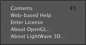
Additionally, you can enter your valid license key in this panel, as well as access LightWave’s About section to check your version number, including information about your system’s graphics card.
Surface Editor
Beneath the Help menu is the Surface Editor. Here, you can apply all of the texturing to your objects. Within the Surface Editor is the Node Editor, new in LightWave v10. We’ll explore its powerful network of surface functions later in this book.
Figure 2.30 shows the Surface Editor open without any surfaces. Surfaces will appear once objects are placed into LightWave Layout.
Figure 2.30. The Surface Editor in LightWave is your home for all surfacing.
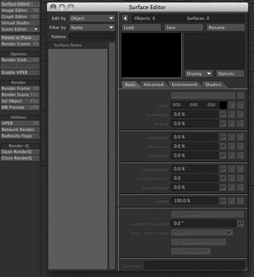
The Surface Editor is easier to work with than you might think. Again, if you think about the process you can easily navigate through the panel. First, tell the Surface Editor which surface you want to work with. Where did you get that surface? You created it in Modeler with the Change Surface requester, accessed via the Surface button at the bottom of the Modeler interface. After choosing a surface, you work your way down the panel from color to luminosity to transparency and more.
Texturing can be a painstaking aspect of 3D animation and art, but as you’ll see in the next chapter, applying basic surfaces and textures is easier than you might think.
Note
Throughout the Surface Editor and LightWave, you’ll see little E and T buttons. These are important. The E allows you to create an Envelope for the given parameter. What’s an envelope? It’s a change in value over time. The E button opens the Graph Editor, which lets you animate that change. The T button allows you to apply textures—-spatial variations in value, distributed over a surface. Pressing a T button opens the Texture Editor. If you click an E or a T accidentally, simply hold the Shift key and click the button again to release. Undo does not work for this.
Image Editor
Below the Surface Editor button is the one for the Image Editor (Figure 2.31), which is used to load and manage image and movie files within LightWave.
Figure 2.31. The Image Editor in LightWave 10 allows you to load images and movies, as well as edit them and apply effects to them.
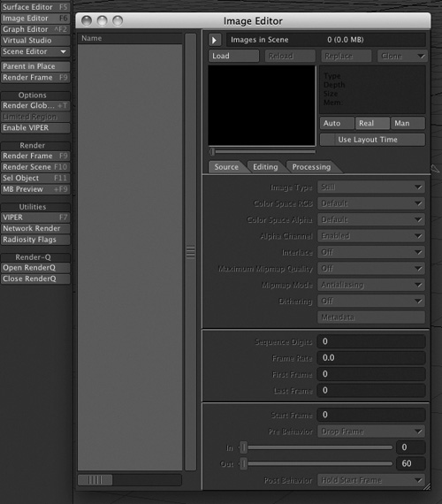
You can do more than just load images in the Image Editor; you can edit them! The Processing tab allows you to apply simple enhancements to your images and movies. Additionally, you can apply textures to your images with the T buttons. You’ll use the Image Editor in the next chapter to load reflection maps.
Graph Editor
Also part of the eight key menus in Layout is the LightWave Graph Editor (Figure 2.32). This panel gives you specific control over the motion channels of your Layout items. Each item, such as a light, camera, bone, or object, has nine motion channels. There is a specific channel of motion for the X, Y, and Z axes for Movement, Scale, and Motion on the H, P, and B (heading, pitch, and bank) for Rotation. You can control all of these channels in the Graph Editor.
Figure 2.32. The LightWave Graph Editor offers specific control over motion channels for your Layout items.
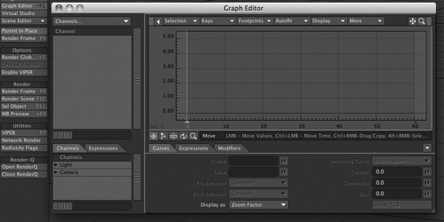
In the Graph Editor, you can adjust the timing of specific channels. For example, say you’ve created a spinning top. You have rotated the top over 30 frames, but you need it to continue for 300. Rather than re-keyframing it, you can use the Graph Editor to “repeat” the past behavior of that specific motion channel. But you can do so much more, such as edit keyframes or create them. You can apply various motion plug-ins, such as a texture environment to the Y (up and down) motion channel to simulate an earthquake. As you work through tutorials in this book, you’ll use the Graph Editor to perform these functions as well as learn how to navigate the panel.
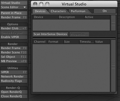
Virtual Studio
LightWave 10’s new Virtual Studio is an amazing addition to this feature-rich program (Figure 2.33). The VSE allows you to interactively work through your scenes using a virtual mouse, such as those from 3Dconnexion. You even can hook up a video camera (along with an optional intersperse device) to virtually walk through your 3D scene. Be sure to watch the Virtual Studio video on the book’s DVD.
Figure 2.33. The Virtual Studio in LightWave 10 allows you to work interactively within a scene with a third-party device, such as a 3D mouse from 3Dconnexion. You can view a video on the book’s DVD showing how the Virtual Studio works (3D_GarageVideosCH2CH2_VirtualStudio.mov).
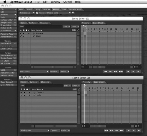
Scene Editor
In the past, you accessed the Scene Editor by clicking a button. LightWave offers a drop-down menu for opening different versions of the Scene Editor—the newer version of the Scene Editor or the classic version you may know and love.
The LightWave Scene Editor is quite powerful, incorporating spreadsheet capabilities, a Dope Sheet, and overall editing of various scene parameters. It does not give you control over every aspect of LightWave, but it can significantly improve workflow by allowing control of multiple items at once. There are five main areas within the Scene Editor: Items, Surfaces, Channels, Property, and Dope Sheet. Exercise 2.5 guides you through a quick overview of the tool.
Exercise 2.5. Working with the Scene Editor
- From the File drop-down menu, select Clear Scene.
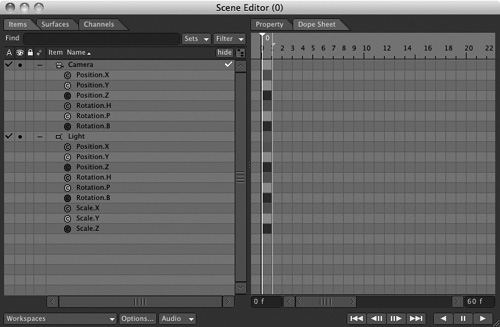
- From the Scene Editor drop-down menu, select Open. Because of the design of the Scene Editor, you can have multiple instances of the panel open at the same time; to do so, simply select New Instance. Figure 2.34 shows the Scene Editor panel.
Figure 2.34. A new instance of the LightWave Scene Editor is created, and the panel appears. You can have multiple instances of the Scene Editor open as well.
- On the left of the panel are the items in your scene, currently just one camera and one light. Figure 2.35 shows that by clicking the small mark in front of an item, you can expand it to see its channels.
Figure 2.35. The left side of the Scene Editor contains the items you want to control.
- At the top left of the Scene Editor are three tabs: Items, Surfaces, and Channels. Click the Surfaces tab and the list changes, giving you access to any surfaces in your scene.
- After you’ve selected certain surfaces to work with, you can select them on the right and make changes. This is useful for quickly seeing and editing all of your surfaces outside of LightWave Surface Editor. Figure 2.36 shows a simple scene loaded so you can see the surfaces.
Figure 2.36. With a simple scene loaded, you can quickly see controls for enabling group editing of surfaces.
Dope Sheet
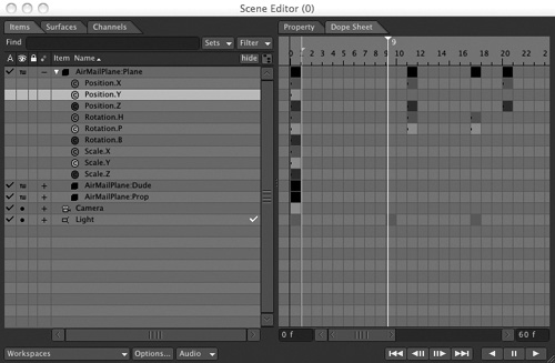
Within the Scene Editor is the Dope Sheet. You can find it in a tab on the right side of the panel. After you set up keyframes and complex motions, especially for characters, the Dope Sheet will be your best friend. The Dope Sheet allows you to see all of your keyframes for multiple items at once. You use it to set the times and numeric offsets, and even to erase keyframes. When you select specific keyframes in the Dope Sheet, you can change their settings values and edit them in the Graph Editor. Figure 2.37 shows Dope Sheet contents for a character scene loaded from the LightWave content directory.
Figure 2.37. When a scene with keyframes is loaded, the Scene Editor’s Dope Sheet gives you enhanced control over time, movement, and other parameters.
The Scene Editor is powerful, and to show its uses, we’re going to dive right into it in some tutorials later in this book. This chapter’s coverage should give you a quick overview of the power behind this cool new addition.
Parent in Place
The Parent in Place button is an on-off switch. When activated, it lets you parent (or unparent) items (objects, lights, etc.) to other items while preserving their keyframed positions and rotations. Parenting and unparenting with this option disabled can cause items to move in unwanted ways.
You’ll access and use these key tabs and menus often, which you’ll see as you work your way through various tutorials in this book. First, read on to learn about the tool categories of the six main menu tabs in Layout.
Items Tab
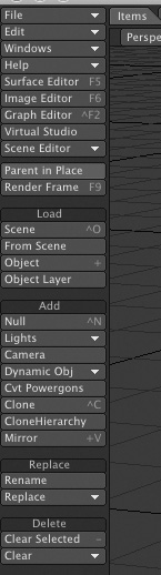
Across the top of the Layout interface are six key menu tabs you’ll find yourself accessing often. The first is the Items tab (much like Modeler’s Create menu tab), which is where you can find the simple item controls, as shown in Figure 2.38. Here, you find one-click load tools, which replace, add, and delete functions. In previous versions of LightWave, it took a number of clicks to access these tools, and after a while it became a bit annoying.
Figure 2.38. Layout’s Items menu tab and its toolset, which allows you to load scenes and replace, add, and delete objects.
Load
The first category you see within the Items tab is labeled Load. Tools within this category let you load a scene, which is an entire project containing lights, motions, and objects. You can also load just an object into your scene with the Load Object button. Loading an object is the way to begin creating a scene. Loading new content overwrites whatever you have in Layout, so be sure to save before you load. The category also contains a button for the previously discussed Load Items from Scene command, found under the File drop-down menu, and the Object Layer button. This allows you to load a specific layer of an object. Let’s say you create a complex living room, with 12 layers. Layer 5 contains that awesome flat panel plasma television you modeled (because your spouse won’t let you buy it!). To load it, select Object Layer, choose the object, and then choose the layer in the requester that appears.
Note
When working in Layout, you’ll often reload work you’ve already created. When you apply textures to your objects, you need to be sure to use the Save All Objects command from the File drop-down menu. This saves any textures or surface settings to your objects. Saving the scene alone does not save the surfaces on objects. Saving the scene saves only motion data, light data, and whatever elements you’ve added to the scene. Colors and textures are saved with objects. Therefore, when you reload your objects, the textures and surfaces you’ve applied will load as well.
Add
With the Add category of the Items tab, you can easily add items to your scene. These items include null objects—single points that do not show up in the render but help facilitate control throughout your animations—which are useful for parenting, grouping, and effects. Tools in the category also make it easy to add dynamic objects, such as particle emitters, wind, gravity, and collision items. Also within the Items tab’s Add category are tools with which you can mirror and clone selected items at the click of a button.
Replace
Replacing objects is easier than ever before with the Replace category under the Items menu. Perhaps you need to replace a simple stand-in object with a high-polygon model for final rendering. Not a problem; just select the item and choose Replace. Also, tools here let you rename any item, including lights, cameras, and other objects.
Delete
The Delete category within the Items tab can be used to quickly clear a selected item or group of items all at once. Use this category for quick-click deletions.
Modify Tab
You might find that you visit the Modify tab often while working in Layout. Of course, you’ll see the same familiar eight menus at the top, starting with the File menu. But if you look farther down as in Figure 2.39, you’ll see five categories of tools.
Figure 2.39. The Modify tab contains some of Layout’s most frequently used tools.

Translate
The first category, Translate, houses several Move tools. These are all translate-type functions, as in Modeler. Use them for any item in Layout from bones to objects to lights. It’s best to learn their keyboard equivalents too, such as the t key for Move.
Rotate
You’ll find the Rotate tools just below the Translate tools. You can rotate any item and specify its pivot point. You’ll learn about pivot points during the tutorials in this book.
Transform
Not to be confused with Translate, the Transform category offers various sizing tools, including Squash and Stretch.
General
The next tool category under the Modify tab is quite important to your workflow. Although the category title says General, the options within this category are anything but! They’re more global than they are general. You’ll find options for the coordinate system, which determines how an item in Layout is controlled in relationship to the 3D world that is Layout. Earlier in the chapter, we characterized LightWave Layout as a big, invisible sphere in which you work. When you change the coordinate system, you tell LightWave to adjust the relationship between the world’s coordinates and the items.
Figure 2.40 shows the Coordinate System category selections. You’ll also find the Reset button. This is handy for keeping track of your items. Let’s say you move your camera around, and then at some point lose track of it. This can happen with any item, even a light. If you first select Rotate (also from the Modify tab) and then click Reset, the rotation resets to the 0,0,0 setting. The same applies for Move. Keep this in mind when you’re ready to scrap what you’ve done and start again without redoing your entire scene.
Figure 2.40. The Coordinate System tool category within the Modify tab enables key changes used in animation.

To better understand the coordinate system, look at Figure 2.41. This is the default LightWave layout, where the X-axis is left and right, the Y-axis is up and down, and the Z-axis is forward and back. But the coordinate system is set to Local.
Figure 2.41. LightWave Layout, with the coordinate system set to Local.
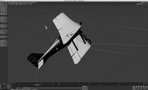
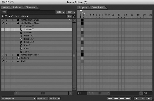
The object in the scene, the airplane, has default coordinates set to Parent in the Modify tab. That means the object’s coordinate axes, represented by the arrow-shaped red, green, and blue handles you use to move it along each axis, align with those of the overall layout. The object’s green Y-axis handle stands vertically; its red X-axis handle lies down to the side, for left and right; and its blue Z-axis handle points toward the back of the Layout interface. With a local coordinate system, the object will be able to move upon its own axis, rather than the world axis within the scene.
Now look at Figure 2.42 (on the next page). in which the coordinate system is set to World. This makes the object’s control handles align with the X, Y, and Z axes of the scene. The airplane object is rotated so that it’s leaning upward within the scene; if you use its green Y-handle to move it upward, it will now rise at an angle relative to the overall scene, rather than straight up and down.
Figure 2.42. The object’s transform handles are now changed because the coordinate system is set to Local.

You’ll use this feature often when working with bones for character animation, as well as mechanical animations. Many times, when setting up hierarchies of parented objects you’ll need to change between Parent, World, and Local. Parent and World coordinates are essentially the same thing, except that if your object is parented to another item, it takes on that item’s coordinates.
As you work through the tutorials, you’ll see how this all comes into play. But remember: As you’re setting up your animations, if something does not rotate or move the way you want it to, look to the Coordinate System tool category in the Modify tab.
Tools
Finally, the Tools category found under the Modify tab is the location of some very powerful tools. As you can see in Figure 2.43, these tool names aren’t as self-descriptive as the Translate or Rotate tools. These commands are some of LightWave’s most important features.
Figure 2.43. The Tools category is home to the IK Boost Tool, as well as Move TCB and others.
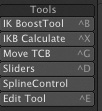
IK Boost Tool
The “IK” in IK Boost Tool stands for inverse kinematics. It is a powerful system primarily used for, but not limited to, character animation. It was originally designed for dynamic simulations with bones and really had nothing to do with character work. However, over the years LightWave users have put it to work any way they can. But part of the IK Boost Tool is Bone Dynamics, which you can learn more about from the video on the book’s DVD (3D_GarageVideosCH2CH2_BoneDynamics.mov). What is inverse kinematics? In the simplest explanation, it is a system for determining how characters move based on the positions of their limbs and joints, much like a marionette on strings: When you move the string attached to a puppet’s hand, its arm follows, moving in a specific way based on the length of the forearm and upper arm and the position of its wrist, elbow, and shoulder joints. That’s it! You’ll be setting up your own IK in the upcoming character animation chapters.
The IK Boost Tool applies IK to a hierarchy of joined objects or bones and allows you to instantly set parameters, limits, and controls for every aspect of your hierarchy.
IKB Calculate
After you’ve set up inverse kinematics and bone options with the IK Boost Tool, you can simply click the IKB Calculate button to “capture” movements generated through inverse kinematics in the form of animation keyframes. This is used for bone dynamics especially. You’ll see this in full action later in the dynamics chapters of this book.
Move TCB Tool
The Move TCB command is sort of a new incarnation of an old feature. When you create a motion path with an object, LightWave creates a curve. Tension, Continuity, and Bias (TCB) are settings you can adjust for each keyframe on a motion curve. A common application is to set a positive tension for the keyframe at the end of a motion, to make the moving object “ease into” place. If this has always been possible in LightWave, then what’s the big deal about the Move TCB button? Up until now, you had to open the Graph Editor, select the specific channel(s) to edit, and apply the appropriate T, C, or B settings. Now, you can use the Move TCB tool directly in Layout. You can see your settings down at the bottom left of the Layout interface in the Info area. All you need to do is press Control+G for the selected item to activate, click and drag in the Layout to set Tension, hold Control and drag to set Continuity, and then right-click for Bias.
Sliders
The Sliders tool lets you attach slider controls to items in your scene for specific control over their behaviors. This is helpful during character animation or precise movements where you want an item to move between two specific ranges. A slider allows you to set minimum and maximum values for a specific action or behavior. Then as you work out the details of your animation, you can simply drag the slider to adjust the attribute within that range. This works on move, rotate, size, and so on.
Spline Control
Spline Control is a tool that, when active, allows you to see a visible and controllable motion path for a specific item. Select the item and turn on Spline Control, and you can click and drag the control handles that appear in Layout to change the shape of the object’s motion path.
Edit Tool
Click this little bugger and you’ll find that it seems to disable any movements in Layout. But wait! It is actually a very cool little tool. Let’s say you added a particle emitter to Layout. Click the Edit Tool, and your particles will be identified numerically. You can then select any one of those particles and move it or delete it. This is great for those annoying particles that won’t behave or that just don’t belong. Get rid of them.
Setup Tab
The Setup tab in Layout is your pit stop for all things skeletal—that is, this is where you find controls for bones. Figure 2.44 shows the menu with its tools.
Figure 2.44. The Setup tab in Layout is where you find all the tools needed to work with bones (LightWave’s deformation tools) and the Layout equivalent of Skelegons.
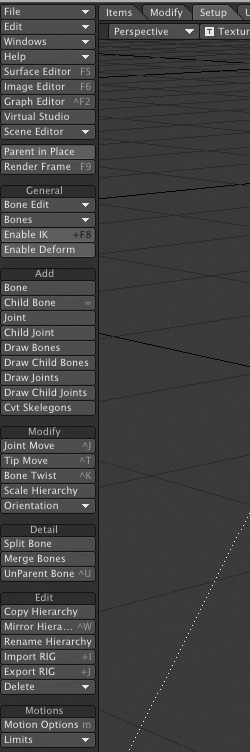
General
Yes, there is another General category—this time it’s under the Setup tab, and we’re talking about deformation tools. The General category offers Bone Edit functions and global settings for activating (or deactivating) bones and inverse kinematics.
Add
The Add category in the Items tab was all about objects, but in the Setup tab, the Add tools concern all things bones. Tools in this category can be used to add a bone, add a child bone, draw bones in Layout, and draw child bones. But another important tool is labeled Cvt Skelegons. This is the Convert Skelegons command that you’ll use to change Skelegons (created in Modeler) into bones for use in Layout. Without this, Skelegons in Modeler are useless.
Note
Bones are deformation tools, meaning they deform your objects—not only animated characters but also such items as a curtain blowing in the wind, or the pages of a book curling. Throughout the character animation chapter, you’ll find yourself guided to these tools for adding and editing bones, splitting them, and much more. In Chapter 1, “LightWave Modeler,” we introduced Skelegons. When you create Skelegons in Modeler for an object, they are converted to bones in Layout. You control, edit, and adjust those bones in the Setup tab.
Modify
Once you’ve added bones to your scene, at some point you’ll need to modify them. The Modify tool category provides all that’s necessary to adjust your bones. These powerful tools let you move bones’ joints and tips, and twist and scale bones. They are handy for properly setting up a perfect character rig.
Detail
Modifications are great, but sometimes when working with bones you need to control more specific details. The Detail tab offers tools to split bones, and not just once. You can take one bone and cut it into four without destroying the hierarchy of your setup. This is useful when you’ve put a bone into a foot, for example, and then realize you need another one so the foot can bend! You’ll also find Bone Fuse, which allows you to put two split bones back together, just in case you didn’t want to split them after all. And you can use the UnParent Bone tool here to remove a bone from its hierarchy.
Edit
Again, all of the tools within the Setup tab relate to bones. Use tools in the Edit category to copy hierarchies, rename them, save them, and load them.
Motions
One small category within the Setup tab relates to bones but also, potentially, to every other item in your scene. You can use the Motion Options tool in the Motions category to access a variety of motion tools and plug-ins. This can be for bones, lights, cameras, objects, or any effect item in your scene. Additionally, you can record minimum and maximum joint angles with the Limits drop-down selection.
Utilities Tab
Whenever you need to add plug-ins, edit them, or work with LightWave’s LScript scripting language, you can click over to the Utilities tab. Figure 2.45 (on the next page) shows the menu tab and its tools.
Figure 2.45. The Utilities tab is home to command tools, LScript programming tools, and plug-in tools.

Commands
The Commands category offers controls for looking up your command history or entering specific commands for LightWave to follow. Additionally, if you want to keep track of commands you’ve used, use the Save Cmd List option. Refer to this for similar projects.
LScript
The LScript category is home to LightWave’s custom programming language. Here, you can load preexisting LScripts, use the LScript compiler to build your own, and use LScript/RT to preview how they’ll run. Note that the LightWave v10 documentation incorrectly describes a fourth tool in this category, LScript Commander. This powerful tool is actually found in the Additional drop-down of the Plugins category (described below), under the name LS Commander. It lets you create your own plug-in that loads an object, saves it, and then saves the scene, all in one button!
Plugins
The Plugins category is where you find the tools to add individual plug-ins, load multiple plug-ins with the Edit Plugins tool, and quickly find the last-used plug-in. Within this category is the Master Plugins panel, which is where you can load Master class plug-ins, such as LScript Commander. You also see the Additional list, where you can find additional plug-ins and any third-party plug-ins you might have added.
Render Tab
Rendering is the process by which LightWave generates the final output of a scene, using all of the lighting, surfaces, textures, animations, and environmental effects (wind, gravity, and so on) that you create in Layout. If a scene is animated, of course, the process can yield anywhere from hundreds to millions of rendered frames.
In earlier versions of LightWave, rendering tools were sort of hidden—kind of unusual for something so critical to the 3D animation process. If you are a veteran user of LightWave, you’ll love the Render menu tab (Figure 2.46). When it’s time to render, LightWave v10 puts the tools you need right in front of you.
Figure 2.46. The Render tab encompasses all of your necessary render tools. Without these, no final outputs!
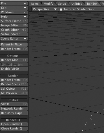
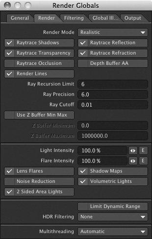
Options
The Options tool category houses the Render Globals menu button, where you’ll find tools for setting up all of your animation characteristics. Use this panel to set camera resolution for single-frame renders, arbitrary renders, and full-frame animations. You can also set filtering methods, global illumination, and more, all from this one panel (Figure 2.47). You’ll work through this panel and see how to render locally and over a network in Chapter 12, “Rendering Animations.” This category also is where you’ll find the Enable VIPER button. This is sort of an on/off switch for VIPER, LightWave’s virtual preview render system, which we’ll discuss shortly.
Figure 2.47. The Render Globals panel, accessible from the Render tab’s Options tools.
Render
The presence of a Render tool category within the Render tab might seem confusing—or at least redundant—but it all makes sense: The Render tools let you click a button to render a single frame, scene, or selected object, or to preview a motion blur right in Layout. Click MB Preview to see any motion blur your scene might be using. You can also see that there is a Render Frame button. This is why the tool was dimmed earlier in the chapter when you edited menus.
Utilities
The Utilities category of the Render tab is where you find the tools for additional render options. First is VIPER, short for Virtual Interactive Preview Renderer. You can use VIPER to instantly see changes to surfaces, particles, and volumetrics, without performing a formal render. This saves time! You’ll use VIPER in the next chapter’s tutorials. Another Utilities tool, Network Render, enables you to tie other computers on your network into your rendering. This is especially valuable because it doesn’t require copies of LightWave to be installed on the other computers that help yours with rendering.
Note
It should be noted that VIPER is different from VPR. While the new VPR allows full-scene previews directly in Layout, VIPER is quite helpful for previewing Hypervoxels for particle dust, explosions, and other surfacing properties.
View Tab
The next menu tab across the top of Layout is the View tab. Here, you can find the necessary tools to control your Layout viewports (Figure 2.48).
Figure 2.48. The View tab and its associated tools manage Layout’s viewports.
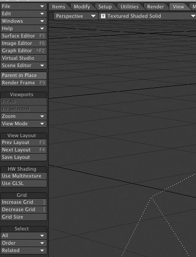
Viewports
The sets of tools available in this menu give you additional control when working in Layout. Earlier in this chapter, we discussed the viewports, and you saw how to set up multiple viewports. The Viewports category in the View tab gives access to buttons that control those views. You can also use the Fit All and Fit Selected commands to quickly bring your items to view. Note, however, that these tools only work in certain viewports, such as the Top or Side views.
View Layout
The View Layout tools let you jump between preset layout views, such as single, quad, and so on. If you set up your own view and perhaps click and drag the center of the windows to adjust, you can save that particular layout with the Save Layout button.
HW Shading
The HW Shading, or hardware shading, option enables computers with certain video cards to display multiple textures within Layout. It also enables supported cards to use a high-level shading option known as GLSL, or Open GL Shading Language. Not all video cards support these options, so check the specifications for your particular video card before applying these.
Grid
Also within the View menu is the Grid Size control in the Grid category. If you recognize that LightWave is a big 3D universe that you work within, it should be easy to understand that the Grid Size is the default unit of measurement you work with. In Layout (and Modeler, too), Grid Size is always displayed in the lower-left corner of the LightWave workspace. By default, this measurement is 1 meter in size, as you can see in Figure 2.49.
Figure 2.49. LightWave Layout’s default unit of measurement, Grid Size, is 1 meter. The Grid Size can be increased or decreased as needed

This means that every grid square you see in Layout, from any view, is 1 meter in size. Count three squares, and that’s 3 meters, and so on. The reason you can increase and decrease the Grid Size in the View menu is because not all objects are scaled equally. For example, if you load in a Mars rover spacecraft, your unit of measurement automatically adjusts to the fit the size of the craft. You should be able to move and rotate the object just fine. If you load in the planet Mars, and it is built to scale, the Layout Grid Size might jump to 5 kilometers and your rover will essentially disappear! This is because LightWave’s grid adjusts itself to fit this large object. If you find your rover and move it, it will shoot off the screen with the slightest mouse movement. If this happens, you need to decrease the grid size.
Note
Adjusting the grid appears to change the size of the camera and lights, but it really doesn’t. It only changes the relationship of those items to LightWave’s world.
Select
The last category in the View tab contains the Select tools. Here, you can choose from various ways to select objects, lights, and cameras. You can choose to select by name or search by name. You can also select related parent or child items here, in addition to selecting in order, from one item to the next. A quicker way to select, however, is to click the item in Layout and then press the up or down arrow key on your keyboard to select the previous or next item, respectively.
Modeler Tools Tab
The last tab at the top of LightWave v10 Layout is Modeler Tools (Figure 2.50). This provides some basic modeling tools within Layout. Nowhere near as powerful as the tools in Modeler, these are mostly useful for setting up simple objects as placeholders. You might not use this area very much, but it can come in handy on occasion when you need a quick primitive object for a scene.
Figure 2.50. The Modeler Tools tab makes basic modeling possible within Layout.
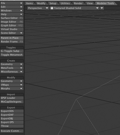
Toggles
Tools in the Toggles category are really switches that turn on and turn off useful functions that were available only in Modeler in previous versions of LightWave. G-Toggle Subpatch globally activates and deactivates subpatch objects you create in Modeler. You might turn subpatches on in Layout when fine-tuning surface attributes, and then turn them off to speed up animation previews. Metamesh Toggle works the same way on objects built using Modeler’s Metamesh tool; you can turn this feature on and off here as well, allowing you to work with simpler objects.
Create
In this category, you can create simple geometric shapes, including wedges, toroids (doughnuts), and other primitives. But in order to do so, you need to first create a null object. Do this from the Items tab, under the Add category.
Modify
In this area, you can modify the geometry you’ve created, with tools such as Squash and Stretch. You can also work with VMaps (vertex maps) that you might have set up in Modeler, or use the Apply, Rotate, and Scale Morph commands.
Import
In this section you have tools that allow you to import EPS and motion capture files.
Export
Animators often work with more than one program, and LightWave has set up tools that allow you to save 3DSs, OBJs, and other popular formats for use in other applications.
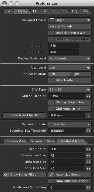
Preferences
LightWave, like many programs, has its own set of preferences. However, because LightWave is not native to particular operating systems and utilizes its own custom interface, accessing these options is not as easy as finding an Edit button at top of your computer screen. Instead, press d or o. The d key calls up Display Options, as shown in Figure 2.51.
Figure 2.51. Open LightWave’s Preferences panel by pressing the d or o key. Here, you can see the Display Options tab, which opens when you press d.
Note
The updated Preferences panel is quite robust. To learn more about this updated LightWave v10 panel, be sure to view the Preferences movie on the book’s DVD (3D_GarageVideosCH2CH2_Preferences.mov).
If you had pressed o, the General Options tab would have appeared, but both panels are embedded in the Preferences panel. Within the Display Options tab, you have specific control over settings that pertain to what you see in Layout. These are options concerning grid size, overlay colors, and many OpenGL options. The OpenGL, or Graphics Library, is the color shaded and textured views you see in Layout. Your video card determines how many OpenGL options you can support, but these days even the simplest gaming cards work tremendously with LightWave. You can tell LightWave to turn on many OpenGL options concerning lens flares, textures, reflections, and even transparency. The new Preferences panel in LightWave v10 is extensive, but there are a few key areas you can read about here. For the rest, check out the video on the book’s DVD.
Bounding Box Threshold
An important value in the Display Options tab is Bounding Box Threshold. You might have installed LightWave and hopped right into Modeler. The model you created ended up being made up of 5000 points and 5200 polygons. When you send your object to Layout for animating, you see the object, but as soon as you move it, it turns into a wireframe box. What’s going on? This is LightWave’s way of saving system resources. If your object is made up of too many points and polygons, it can significantly slow down your system when you try to move or rotate it. This is because LightWave needs to redraw the object in real time on every frame. If it can’t keep up, it stalls.
The Bounding Box Threshold option allows you to set a limit on when LightWave has enough, so to speak. A basic 64 MB video card can have a bounding box threshold set to about 40,000. In other words, if your object is 35,000 polygons, it stays drawn all the time. If it’s more than 40,000 polygons, it turns into a bounding box upon any movement. Set this one time, and you can leave it. Note that this does not affect rendering in any way.
General Options
If you press o for General Options, you’ll jump to a tab with variables that are very important to your working environment, as they help you select color picker style, dialog menu types, control for auto key creation and more (Figure 2.52). You can use these settings to change LightWave’s Input Device from a mouse to a tablet, and to set how your frame slider is viewed. By default, the LightWave timeline shows frames, but you can change this to show SMPTE (Society of Motion Picture and Television Engineers) timecode units, film timecode, or time in seconds. The most common setting is frames, as in frames per second.
Figure 2.52. The General Options tab within the Preferences panel contains key settings for LightWave Layout.
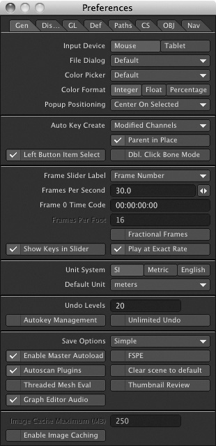
LightWave also offers its own custom color picker, which you can turn on in this panel. When picking colors for backgrounds or surfaces, for example, this causes LightWave to calls up its own custom color picker rather than the one built into your Windows or Mac system software.
Finally, as mentioned previously, Layout offers multiple undo levels, which can be accessed in this category. Be careful with this. You can’t undo everything; primarily, this command is useful for undoing keyframe motions. Let’s say you add a few keyframes to your animation and decide you don’t like them. Press Control+Z a few times to undo. Again, if you accidentally click Remove Texture in the Surface Editor rather than Use Texture, there is no undo for that! So be cautious.
The Next Step
This chapter has taken you on a brief overview of Layout and how it’s organized. You have seen how the menus are arranged and how they work, and you took a tour of the tools available to you.
There is more to learn, and it’s about to get more exciting. Soon, you’ll be working completely on tutorials, learning firsthand the tools and how they work. What’s more, you’ll learn why you’re instructed to do what you’re doing. Subsequent chapters guide you through the basics of lighting, textures, and motions. Then, you’ll take this knowledge into longer, full-blown projects.
Too often, books just click you through, leaving the figuring out up to you. Inside LightWave v10’s tutorials are designed to ramp you up from beginner to intermediate to advanced tutorials, offering clear explanations along the way.
We have a big journey ahead of us, so take a break, get some caffeine, and get ready to rumble and learn all about creating textures in Chapter 3.