
Chapter 1. LightWave Modeler
I used to think there were two types of people who create 3D imagery. But over the past 18 years or so, I’ve realized that there are really three types. The first two types are modelers and animators. The third is that person who has no clue as to what it takes to create a 3D model, texture it, light it, or bring it to life. To this type, creating 3D imagery means pushing a button and waiting for the computer to do it. For the purposes of this book, we’re going to forget about the push-button types, because no matter what you say or do, they simply won’t get it. Some of these people are your clients or bosses, which leaves the real work of creating 3D imagery up to you.
It also raises the question: Which of the remaining two types of people are you—a modeler or an animator? I’m not saying you can’t be both, but in my experience the 3D modeler is left-brain oriented—logical, sequential, and rational. The 3D animator is more right-brained—random, intuitive, and subjective. The animator also enjoys and understands timing, lighting, and textures.
But these two approaches—like 3D animation and modeling themselves—don’t have to be mutually exclusive. What I’d like to do is mix the left and right brain and have you not only enjoy what you’re doing but also understand it. When I started creating 3D imagery in LightWave, it took me longer to get into a groove with Modeler, whereas with Layout, I felt right at home. Other guys I knew were just the opposite due, in large part, to differences in our backgrounds. With all of that being said, I want to dive right into LightWave Modeler to get you up and running, no matter which side of the brain you favor.
Imagine that LightWave is a virtual television studio and 3D models are your actors. Although some animations can be created with animated textures or photographs, most include 3D models. These models are made up of points, edges, and polygons. This chapter takes you on a tour of LightWave Modeler. Along the way, I’ll explain points, edges, and polygons, and show you how to use them to create 3D objects—which you will then animate and render in LightWave Layout.
LightWave Modeler is where your original 3D animations begin. That’s not to say you can’t start animating right away. NewTek, Inc., the makers of LightWave, have included a terrific amount of prebuilt content for you to use and explore. In fact, you can load a sample scene in LightWave v10 Layout and click the Render button to create your very first animation without ever launching Modeler. But to really know your software, you must first understand what a 3D model is all about.
Note
If you plan to only animate, and never plan to model, you might wonder if you should even read this chapter. The answer is yes! Even if you don’t expect to model in your career, it’s still important to understand LightWave Modeler for a couple of reasons. You may at some point need to import a model from another program. Or, at the very least, you’ll need to assign a surface to parts of your model. You can do that only in Modeler.
Understanding Modeler
When you open LightWave 10 Modeler for the first time, you’ll see a big blank interface with lots of buttons, panels, and menus tucked neatly around the outer edges of the program. Where do you begin? It can be quite intimidating, but it’s easy to stay focused on any task you want to accomplish once you understand the workflow. All the tools are useful, but many modeling jobs require only a few of the tools at once. You’ve probably heard this before: You’ll use only 20 percent of the tools 80 percent of the time. As with any fully equipped software program, some of LightWave’s general-purpose tools get used every day; more specialized ones get pulled out only once in a while, but you’ll find them essential for specific tasks. So you should always know what’s in your toolbox.
Note
Please, by all means, before you go any further, grab the DVD out of the back of this book. Stick it in your computer and watch the video about the content directory. Seriously... go do it. Now.
Key Areas of Modeler
There are practically no limits to what you can create using 3D animation, which means a virtually unlimited number of variables to manage—and a vast number of tools within LightWave to control them all. However, I want you to ignore the overall cluster of buttons in LightWave and concentrate instead on the tools and what you are trying to do.
In other words, don’t get overwhelmed by the buttons. I can’t stress this enough. I’ve trained hundreds of people over the years and this is the first thing I tell them. Don’t just start clicking buttons hoping something will happen, like my Mom does (sorry, Mom, it’s true). There are times when you’ll use only half a dozen buttons and tools for an entire project. Often, your particular type of work may never even unwrap some of the tools and panels LightWave has to offer, and there’s nothing wrong with that.
The goal of this book, and more specifically this chapter, is to help you understand how to use LightWave Modeler and work with its toolset. Even with so many improvements in LightWave over the years, version 10 includes some of the most complex changes to date. LightWave Modeler has been touted as one of the best 3D modelers in the industry, and the latest update makes it a more efficient, powerful tool, with a much-enhanced workflow. This chapter introduces you to that workflow. Here are some of the key areas discussed in this chapter:
• LightWave v10 Modeler interface navigation
• Viewports
• Simple objects
• Points, edges, and polygons
• Selection and deselection
• Subdivisional surfaces
Proper construction of 3D models and animations takes discipline, focus, and a keen sense of direction. And, just as if you were building a cabinet in your garage or redoing the tile in your own bathroom, it also requires careful planning and a full understanding of the tools involved. This is because you want your 3D models to be efficient. You have to construct the models properly so that you can animate them correctly. When you know your tools and methods, the goal is not difficult to accomplish. Your focus should be clear and your work environment should be comfortable. There’s nothing worse than working on a complex model without a plan and in an uncomfortable workspace. Be prepared, both mentally and physically.
3D Modeling in LightWave
Before you start using Modeler, you should become familiar with the medium that is 3D animation. You should understand how the X, Y, and Z axes relate to one another and your LightWave workspace. If you don’t, please refer to the QuickTime movie “3D Animation Basics” on this book’s DVD for a primer.
3D modeling is like interactive geometry. You can begin creating models with simple points and connect them with curves or straight lines. LightWave also gives you a slew of basic geometric shapes such as boxes and spheres to work with, and you’ll see throughout this book just how those basic shapes can be used to create complex 3D models. Before you concern yourself with building complex 3D models, however, let’s take a look at how the LightWave interface is laid out.
Note
Too often, when people work in 3D, either in modeling or animation, they consider only what they see on the flat screen in front of them. Do not make this mistake! Remember that your 3D models are more than just what’s visible in front of you—they have sides, a top, a bottom, and a back, even if you can’t see them.
LightWave v10 Modeler Interface
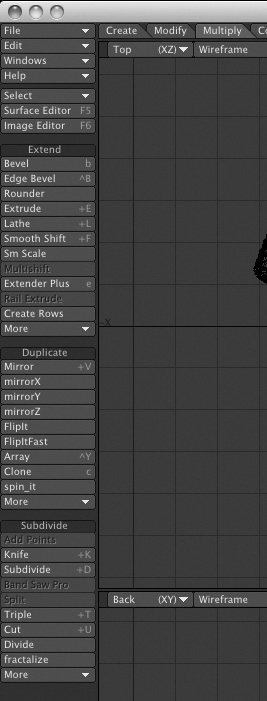
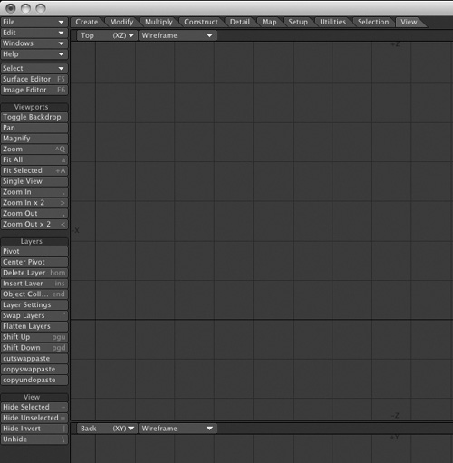
If you’re new to LightWave with version 10, the interface (Figure 1.1) will obviously look unfamiliar. Initially, working through the interface might be frustrating, but if you understand the tools and their arrangement and keep in mind what you want to do, you’ll find using the program simpler than you might expect.
Figure 1.1. The LightWave 3D Modeler interface.
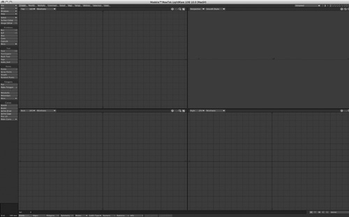
If you’re an experienced LightWave user and have just upgraded to LightWave v10, you’ll notice at first a similarity to previous versions. With version 10, LightWave adds some great new tools and rearranges some preexisting ones to bring them closer to the surface. Both LightWave Layout and Modeler have been significantly streamlined, and navigation has never been easier, but the changes may require some adjustment. In addition, you’ll notice a shift in color for the interface. While it might appear dark at first, research has shown that this neutral gray and blue combination will be very pleasing to the eyes, especially on long projects!
Although much of this book focuses on the modeling tools in action, this section highlights the features of LightWave 10 Modeler. You’ll be able to try them out in just a few steps to gain a strong working knowledge of their functions.
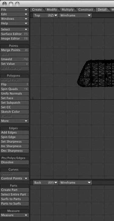
Modeler Viewports
To begin working with LightWave Modeler, you should understand the viewports first. These four windows are the areas that will be your work environment, and by default, they show all sides of your 3D model.
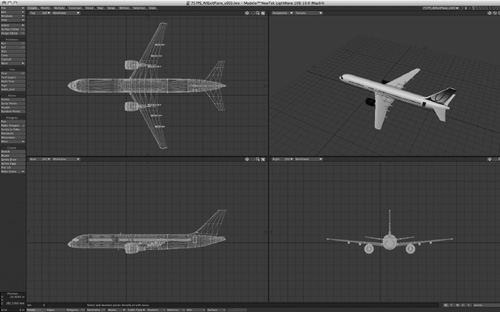
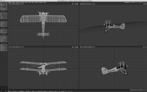
Take a look at Figure 1.2, which shows the same full Modeler interface as Figure 1.1, but this time with a 3D model loaded. By default, LightWave Modeler assigns the viewports Top, Back, and Right views of your model, along with a Perspective view. Each is a little awkward at first, but try to remember this:
• Top view (XZ) provides a view along the Y-axis. You are looking down at the top of your object.
• Back view (XY) looks down the Z-axis. You are looking from the back of your object toward its front.
• Right view (ZY) looks down the X-axis. You are looking at the left side of your object, toward its right.
Figure 1.2. A 3D model of an airplane loaded into LightWave Modeler can be seen from all sides, and the default layout also shows a solid color version.
This may sound confusing, but after you get used to the concept, it will make more sense. And eventually, it’ll even become familiar. For instance, when you get to Layout later, you’ll find that the Back view you see in Modeler is the default view that the LightWave camera sees. The LightWave camera looks toward the back of the object, forward in the scene.
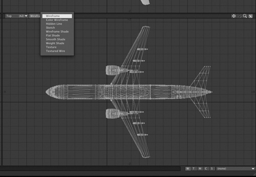
Don’t let this layout of viewports make you feel constrained. You can change any viewport to look any way you like. Check out Figure 1.3 (on the next page), where a close-up of the top-left viewport is shown.
Figure 1.3. A close-up of the top-left viewport, showing a 3D object from above.
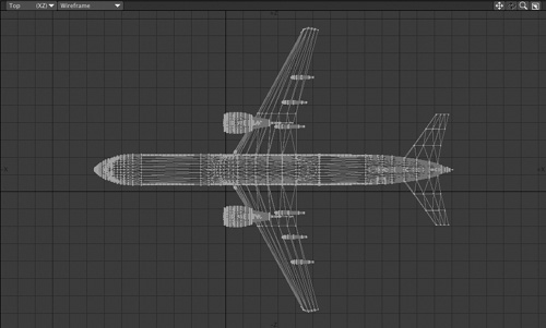
This top-left viewport is called Top by default, and it shows the 3D object from above—you’re looking at the “top” of the object. Notice that at the top of the viewport there are buttons labeled Top (XZ) and Wireframe. This tells you that the particular viewport is set to Top. The XZ means these are the two axes you have control over. Because you’re looking down the Y-axis, you can’t move your object along that axis in this view.
At the top right of the viewport, you’ll see four small icons. These are your viewport position controls. Figure 1.4 shows the buttons up close.
Figure 1.4. The four small icons at the top right of each viewport enable you to move, rotate, zoom, and maximize the viewport.
![]()
Note
Depending on viewport settings, certain position control icons may be dimmed to indicate they are unavailable. In the Top viewport, for instance, the Rotate icon is dimmed because you can only rotate in a Perspective view, not an orthogonal (X, Y, Z) view.
Click, hold, and drag these buttons to use them. Too often, people click them and release, but that’s not how they work. Click and hold to use! The first button (starting from the left) is Move, the next is Rotate, the third is Zoom, and the last is the Maximize viewport button. Click Maximize, and your viewport will become full screen. This is great for getting up close to your model for fine-tuning point position or measurements. To return from a full-screen viewport, just click that icon again.
Note
If your keyboard has a numeric keypad (most non-laptop models do, and some laptops sport them too) you can use its 0 key in place of the Maximize viewport button. (That’s 0 as in zero, and in the numeric keypad only; you’ll use the number keys at the top of your keyboard to change layers.) Be sure your mouse cursor is in the viewport you want to maximize before pressing the 0 key. Press 0 again to return from full-screen mode.
Viewport Customization
You can customize each of the four viewports in Modeler any way you like. Figure 1.5 illustrates that you can assign any or all viewports a Back, Top, Right, or Perspective view. You can make all four viewports Top views if you like, although it might not help your modeling process too much.
Figure 1.5. Each viewport can be set to any view you like.
Something you might change more often than the viewport view is the viewport style—its method of drawing the objects it depicts. Choosing any of the ten settings from the drop-down menu shown in Figure 1.6 (on the next page) lets you visualize models using styles, including Wireframe, Smooth Shade, and Textured Wire. Different styles are better suited to various modeling tasks, as we’ll see later in the book.
Figure 1.6. Each viewport can also have a unique viewport style, such as Wireframe or Textured Wire.
Note
Although LightWave v10 is extremely customizable, the projects in this book will use the default configurations for Modeler and Layout, for the sake of consistency.
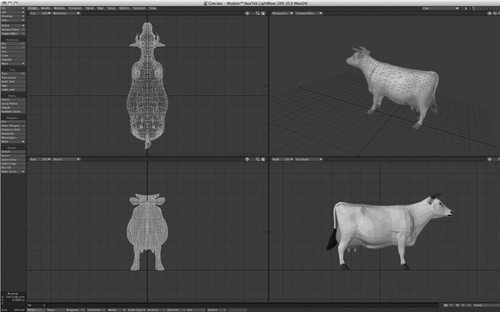
Figure 1.7 shows each viewport set to a different style with the same model loaded, so you can see how flexible the options are.
Figure 1.7. Here, each viewport is set to a different style. There are a total of ten viewport style choices.
Note
Your choice of viewport style will be based on the model you are creating. Often, a good way to work is with the default settings—Wireframe style in the X, Y, and Z viewports, while using a Smooth Shade or Textured Wire style in a Perspective view. It’s totally up to you.
Working with Objects and Layers
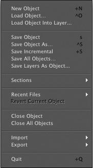
Now you’ll take a look at how LightWave works with objects. From there, you’ll learn about points, edges, polygons, selection, and deselection, while creating a few simple objects along the way. LightWave objects are unique to the program, and have the file extension .lwo. You can load existing objects from LightWave’s content directory simply by pressing Control+O for open (that’s the letter o). But also take a look at the File drop-down menu at the top left of the Modeler interface. Click it, and you’ll see all your common load and save functions, plus a few extras. Figure 1.8 shows the panel.
Figure 1.8. Using the File drop-down menu in Modeler, you can load, save, and perform similar operations.
If you use Photoshop, you are probably familiar with the concept of layers and how they are used if, say, you’re building a billboard ad: You might put a color gradient in the background layer, add text in a new layer, place a picture in another, and so on. Why do you do all this in layers? So that each layer’s contents can have its own set of parameters, such as size, position, effect settings, and so on. If all the components lived on the same layer, you’d have a tough time applying effects to any individual element. LightWave Modeler works in much the same way. Each item that you need to control individually, for purposes of modeling or animation, should be in its own layer.
Note
An object can have multiple layers. You can work with multiple layers at one time if you like (just hold the Shift key to select multiple layers). By the same token, you can also have multiple objects loaded at once.
This means that if your car model has four wheels (and I hope it does), and you want each wheel to be able to roll separately, each wheel must live on its own layer. If a wheel were placed in the same layer as the rest of the car, you’d have to animate the entire layer to make the wheel turn. You will also learn later in the book how layers are used to perform various modeling actions. For now, take a look at the top right of the Modeler interface, and you’ll find a set of ten buttons (Figure 1.9), each representing a layer within a model. Layers within an object translate to actual objects in Layout. A car object with a separate layer for a door, for example, would show up in Layout as CAR:DOOR. The wheel layer would appear as CAR:WHEEL and so on.
Figure 1.9. At the top right of the Modeler interface are the layer buttons.
![]()
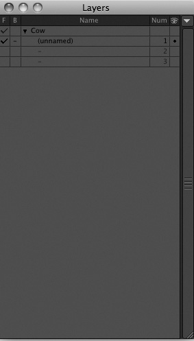
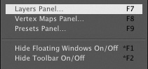
At first glance, if you start clicking the layer buttons, they look like they do nothing. However, they are crucial to properly setting up and building certain types of models. And don’t think that because there are ten buttons you’re limited to ten layers; you can have an unlimited number of layers in a LightWave project. Press F7 and the Layers panel opens (Figure 1.10).
Figure 1.10. Pressing F7 opens the Layers panel, which gives you access to Modeler layers. Here you see a blank Layers panel, because no objects are loaded.
You can also open this panel from the Windows drop-down menu in Modeler, as shown in Figure 1.11.
Figure 1.11. Use the Windows drop-down menu to access the Layers panel if you don’t like the F7 key.
Note
If you’re working on a Mac laptop and nothing happens when you press a function key such as F1 or F9, you need to open System Preferences and tell your computer to allow software applications (rather than the system) to use the function keys. If you’re on a desktop Mac, select Keyboard & Mouse in System Preferences, and under Keyboard Shortcuts uncheck the function keys, such as F9, that you wish to use in LightWave. F9 on a desktop Mac defaults to Exposé’s All Windows command. F9 in LightWave is Render Current Frame. Note that you can change the shortcut for render in LightWave, but the tutorials in this book will use the default settings.
To demonstrate how LightWave Modeler handles existing 3D models, you’ll work with simple models that are included with this book. These will be located in the Objects folder. Be sure you have set up the content directory as instructed in the “Content Directory” movie on this book’s DVD (3D_GarageVideosCH1CH1_ContentDirectory.mov), and make sure to read the Read Me section of the disc contents.
Note
One more plea: Before you do anything else, learn about the content directory! It will save you from lots of headaches. This is the number one problem reported by new LightWave users.
Loading Objects and Naming Layers
The procedure for loading single-layer and multiple-layer objects is the same. Layer information is stored within each LightWave object file, and it’s not something you need to worry about. LightWave object files retain data about changes you apply to them, such as colors and textures.
Note
The sample content included with LightWave v10 comes on a DVD that’s separate from the program installer CD. Look for it in your LightWave software case, and install these files as instructed. You’ll use them in this chapter.
Exercise 1.1. Loading Objects and Naming Layers
- Press Control+O (Windows or Mac) or Command+O (Mac), or choose Load Object from the File drop-down menu and load the Hammerhead.lwo shark object from the Objects/CH1 folder from the book’s DVD. Once it loads, press a to maximize the object within the window. You’ll use this keyboard shortcut quite a bit throughout this book.
Note
When working with keyboard equivalents, it’s best to always keep your Caps Lock off. Many basic LightWave functions are assigned to lowercase keyboard shortcuts, while more complex functions are set to capital letters. These complex functions can create problems if you use them accidentally. For example, pressing q as lowercase allows you to set a surface name. Pressing q with Caps Lock on will quit the program!
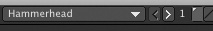
- Figure 1.12 shows the object-selection pull-down and the layer buttons as they appear after the model is loaded into LightWave Modeler. You’ll see that the first layer button is depressed by default, and it contains a small dot.
Figure 1.12. Modeler’s object-selection pull-down shows the name of the loaded object, Hammerhead, and the layer buttons indicate that just one layer is associated with this object.
These dots inform you that there is geometry in that layer, such as points, edges, or polygons. Open the Layers panel (F7) and look at what the listings show. You’ll see the name of the object, and if you click the small white triangle to expand the object’s layers, you’ll see a listing that reads “unnamed.” Unnamed refers to the geometry in the layer, which you’ve yet to name.
- Double-click the last “unnamed” listing, and the Layer Settings panel pop-up will open. If you had multiple layers—that is, objects in other layers—selecting any one of these layers would instantly change your view to that selection.
Note
Just to the left of the ten layer buttons at the top left of Modeler is a number with left- and right-arrow buttons. When you open a model, you’ll see the number 1. This means that you’re working with the first set of ten layers. You can click the right arrow to get to another set of ten, and the number changes to 2. Click again, and you’re in the third tier of layer buttons, and so on. However, this approach is cumbersome, and working with the Layers panel is often a better way to go. Open the panel and put it aside while you work. Unlimited layers, baby!
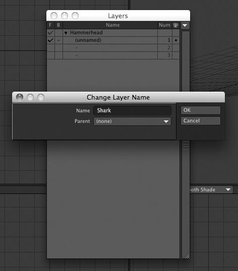
- In the Layer Settings panel, enter Shark in the Name field. If you had another layer with geometry, you could also tell one layer to be “parented” to another. Parenting means that the selected object becomes a child and “belongs” to the parent. Whenever you move, rotate, or scale a parent object in LightWave Layout, objects in its child layers will follow. You’d use this for wheels on a car, letters in a logo, and more. Figure 1.13 shows the operation.
Figure 1.13. By double-clicking a chosen layer in the Layers panel, you can rename it and parent it to other layers.
When you loaded the Hammerhead shark object, you saw that the layer 1 button was selected. If you wanted to add parts to the model, or perhaps build a set of some sort, you would do so in another layer. To accomplish this, you select another layer by clicking it. And as you did earlier, simply double-click the layer listing in the Layers panel to name that layer.
Note
You can load multiple objects into Modeler at the same time. However, unless you specifically cut and paste those objects together in some fashion, you can view only one object at a time. Figure 1.12 shows the layer buttons at the top right of the interface, and to the left of the layer buttons is the Current Object selection list. Any objects loaded into Modeler can be selected from this drop-down list. It’s important to note that each loaded object retains its own layers. Choosing to load multiple objects will not load them into individual layers within the same model.
So, what’s the point of all this, you ask? Even though this is a simple object, all of your 3D objects will be handled in this way. The purpose of naming each layer is to ensure that when you’re animating later, you won’t have to guess which layer is which. Naming your object layers is not necessary, but it’s an efficient way to work and organize. When you save your object, its layers and their names are saved with it. What’s great about this is that you can send a single object to a coworker or client, and all of its parts (such as the wheels), as well as the parenting hierarchy, are contained within.
Foreground and Background Layers
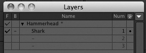
There are a few more things to note about the Layers panel. Looking at Figure 1.14, you can see some additional labels in the Layers panel. The F at the top left of the panel stands for Foreground, while the B stands for Background. Additionally, the Num category displays the layer number and the eyeball hides the model from appearing in Layout. You’ll learn more about this shortly.
Figure 1.14. Additional controls are available in the Layers panel.
As you get into more-complex projects, you’ll use these commands in the Layers panel to place objects in both the foreground and the background. To try this out, follow these steps:
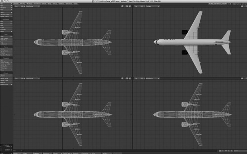
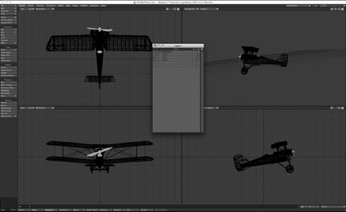
- Load AirMailPlane.lwo object from the book’s DVD, found within the 3D Content folder. This object has three layers, and when first loaded, all are seen in the foreground, as in Figure 1.15.
Figure 1.15. Selecting a layer in the Layers panel brings that layer to the foreground.
- Press F7 to open the Layers panel. Don’t click any individual layer itself, but click the check box beneath the B column (B for background) next to the Plane layer. If you see only the name of the model, click the white expansion triangle to the left of its name to reveal all the layer names. Figure 1.16 (on the next page) shows the model with the plane now as a background layer, signified by a black wireframe.
Figure 1.16. By selecting a layer under the B column in the Layers panel, you can put layers in the background for reference.
Take a close look at the top right of the Modeler interface, and you’ll still see the body fuselage of the plane, but in a dark outline. You’ll see the wheels and other parts still in a foreground layer. You’ve now defined foreground and background layers. The reason for this is threefold: Objects in background layers are used for reference, as separate animation elements, or as modeling tools.
Note
Layer order becomes important when you use foreground and background layers as modeling tools. This topic will be covered later in the book.
You can hold the Shift key and select multiple background layers as well. On the right side of the Layers panel, you’ll see numbers. These are the layer numbers for each layer, and unlike Photoshop layers their order does not affect the appearance of the model.
Layer Visibility
To the right side of the Layers panel, at the top, is a small eyeball icon. Beneath that, next to each layer is a little dot. Let’s say you’ve placed an object in a background layer and used it as a reference to build a new object. If you save your LightWave object and load it into Layout, all layers will be visible. However, if you click that little dot in the Layers panel in Modeler, when the object is loaded into Layout the layer will not be visible. Load it back into Modeler, and it will be there. This is great when you use objects as modeling tools.
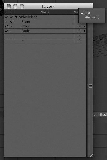
Finally, there’s one more area you should be aware of in the Layers panel: the Hierarchy view option. It’s easy to miss, but at the top-right corner of the Layers panel, there’s a small drop-down arrow. Select it and you see the option for List or Hierarchy. So far, you’ve been seeing the Layers panel in List view. Figure 1.17 shows the Layers panel in List view. This is useful for more complex objects such as characters or mechanical creations.
Figure 1.17. You can choose to view your object layers as a List or a Hierarchy.
There are many more panels in LightWave Modeler, but it’s important to understand how to navigate before you get more involved. Working with the layers is essential to any model you create, which is why it’s covered first in this chapter. Now, to the menus!
Tabs and Menus
Across the top of the Modeler screen you’ll see ten tabs, each representing a different group of modeling tools. This section guides you through the different tabs and explains how they’re organized. Figure 1.18 shows the tabs across the top of Modeler.
Figure 1.18. The LightWave menus are tabbed across the top of the interface. Selecting any of these brings up various tools on the left side of the screen.
![]()
When you select different tabs, different toolsets become available. Think of a toolset simply as a group of tools. Years ago, tools were just floating around in LightWave Modeler, some of them hidden deep within menus. Now, NewTek has significantly streamlined the tools and grouped them quite well. The LightWave Modeler toolset works similarly throughout the program, with slight variations depending on which tool you are using. This next section guides you through the toolset categories within each of the Modeler tabs.
Note
On the top left of the Modeler interface, you’ll find a set of drop-down menus that will always appear, no matter what tab you’ve clicked. These include File, Edit, Windows, Help, Select, Surface Editor, and Image Editor. These selections are the same in Layout and are covered in detail in Chapter 2, “LightWave Layout.”
When working in LightWave Modeler, really think about the process, and you’ll have a much easier time locating the proper tool. For example, say you’ve just started up Modeler and want to build a 3D television set. You want to create something and need basic geometry to get started. OK, head on over to the Create tab. Choose the Box tool, and go. Then, let’s say you want to change it in some way, perhaps rotate it or move it. What are you doing? You’re modifying it, right? You’d go to the Modify tab to find the necessary tools. What if you need to add to this, perhaps by beveling it a bit? Think about a bevel and you might realize that this operation will add to the geometry of your object, so look under the Multiply tab. Many tools in LightWave v10 have been rearranged in ways that make even more sense than in previous versions. If some tools are no longer where you’re used to finding them, keep the task at hand in mind and you’ll probably see that they’ve been moved to a location that makes more sense.
Create Tab
The Create tab calls up the basic tools you need to create geometric shapes such as boxes, balls, discs, and more. Additionally, you’ll find tools to create points and curves. Figure 1.19 shows the tools under the Create tab.
Figure 1.19. The Create tab is home to many basic tools that you’ll need in the course of most modeling projects.
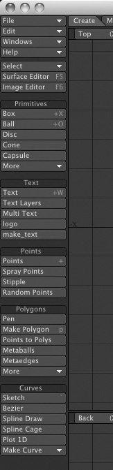
The first thing you’ll see when you click the Create tab is that the toolset starts at the top of the screen on the left side and pretty much runs down the entire left side of the interface! The first seven buttons at the top will always be there, no matter what menu you’ve chosen (unless you customize your interface and change their location, as described later in the book). These key tools are the File menu, Edit menu, Windows menu, Help menu, Select menu, Surface Editor, and Image Editor. These are important areas that you will access often, which is why they’re always accessible from every tab in Modeler.
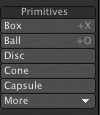
Primitives
At the top of the toolset under the Create tab is the Primitives category, as shown in Figure 1.20. Here you’ll find the tools for creating geometric shapes such as a box, ball, gemstone, and capsule. These basic (and some not-so-basic) geometric shapes are key building blocks for just about anything you want to create. Think about it—the forms of nearly everything around you are based on geometric shapes: a television, a couch, a kitchen sink! A vast number of 3D models start out as primitives, which are multiplied, cut, shaped, and formed into final objects.
Figure 1.20. The Primitives category within the Create tab offers a wide range of basic (and some not-so-basic) shapes you can use to create 3D models.
Text
LightWave is famous for generating spaceships and animated characters but, believe it or not, 3D text is one of its most popular and in-demand applications. As you’ll see in Chapter 7, “Broadcast Animation,” you can make some pretty outstanding broadcast-style animations and graphics with these tools. But what’s more, text objects can also be used as building blocks. For example, you can take the letter C, turn it on its side, extrude it, and you have a slide you can put into a 3D playground. Or how about using the letter E as a building block for creating a 3D maze?
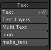
In previous versions of LightWave, to use the text tools properly you needed to first select the Manage Fonts button. Now you have a variety of text tools, shown in Figure 1.21. This tool enables you to load fonts into Modeler. But LightWave v10 has made text creation even easier: It allows you to choose any font on your system by opening the numeric panel for the Text tool. The Text Layers tool in LightWave v10 is so easy to use, it’s just silly. Here, you can instantly create a string of text or a simple logo and have the program instantly add surfaces, while putting each word or letter on its own individual layer. This means you get to animating even faster!
Figure 1.21. The Text tool category is where you’ll find the Manage Fonts command, the Text Layers tool, the Multi Text tool, as well as the Text creation tool.
Points
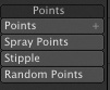
Often you’ll need to build an object from scratch, starting not with a box or a ball, but with a point. Later in this chapter, you’ll read about points, edges, and polygons, but essentially, points make up polygons, sort of like connect the dots. The Points category gives you the tools to create points one at a time, in clusters with the Spray Points tool, or with the Random Points generator. Figure 1.22 shows the category.
Figure 1.22. The Points category offers tools to create single points or clusters of points. Points, as you know, make up objects.
Polygons
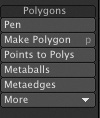
Many 3D shapes you’ll create in Modeler begin as simple 2D polygonal shapes. And just because primitive shapes make basic objects and points create individual points doesn’t mean that you can’t create simpler polygonal objects. For example, the Polygons category has a tool called Pen, which is similar to the Points tool except that as you create with the Pen tool, polygonal lines are automatically generated between each point; the dots are connected automatically. You can convert selected points to polygons or use the Make Polygon command, which you can apply after you’ve used the Points tool from the previous category. Additionally, you can create some organic objects with the Metaedges and Metaballs tools. Figure 1.23 shows the category.
Figure 1.23. The Polygons category offers polygonal creation tools.
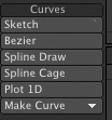
Curves
The last category in the Create tab is Curves. This category includes tools for generating curves from points you’ve created. Curves are used for many things, such as motion paths and extrusion paths as well as shaping models. The Sketch tool enables you to just click and draw, and when you release the mouse button you have a 3D curve! You can use curves to build objects with splines. As you’ll learn later in this book, splines are useful for building organic objects such as boats, curtains, or sometimes characters. Another key tool in this category is Spline Draw, with which you can precisely create curves, not only for models but also for text or custom shapes. Figure 1.24 shows the tools in this category.
Figure 1.24. You can use curves for text, characters, motion paths, and more.
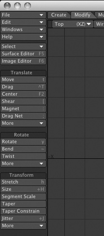
Modify Tab
The Modify tab—sounds simple enough, right? Well, it is. Anytime you want to modify your object in some way that does not require adding or removing points or polygons, you need to use a modify function. Click this tab and at the top left you’ll see the seven tools available in every tab. Below them, you’ll see three toolset categories: Translate, Rotate, and Transform (Figure 1.25).
Figure 1.25. The Modify tab is used when you need tools to move, rotate, or size your object.
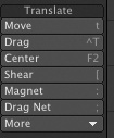
Translate
No, this category doesn’t contain tools to make objects fluent in foreign languages. Its tools are used to move objects in 3D space (Figure 1.26). Typically, the 3D industry calls a move function a translation. The Translate category contains tools like Move, Drag, Magnet, and a few others. Each tool repositions your object in some way.
Figure 1.26. Tools in the Translate category let you move your geometry around—both points and polygons.
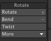
Rotate
This category (Figure 1.27) is almost self-explanatory. Of course, you can rotate points or polygons with the Rotate tool, but there’s much more you can do with it. You can also bend, twist, and even use the cool Vortex tool (in the category’s More drop-down). Other tools like Rotate to Ground or Rotate to Normal provide extra control for precise rotations.
Figure 1.27. The Rotate category contains your basic rotation tools, as well as some cool extras like Vortex.
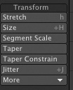
Transform
Transform is a sizing function, so anytime you hear seasoned animation veterans talk about “transforming the object,” they’re not talking about a Saturday morning cartoon. The Transform category includes modification tools such as Size, Stretch, Pole, and others (Figure 1.28). Every tool in this category controls object size in some way. For example, Size scales your object or selection equally on all sides. Stretch sizes your object or selection on a specific axis. Use the Transform tools when you want to scale or distort objects or selections.
Figure 1.28. The Transform toolset is the place to find size/scale tools.
Multiply Tab
Tools in the Create and Modify tabs are generally easy to wrap your brain around. When you get into the Multiply tab (see Figure 1.29), things get more complex. Within LightWave, multiply means to add onto a selection, and the tools within this tab do so in a variety of ways. You’ll use these tools often in later chapters. For now, read on to find out what the categories in the Multiply tab can do for you.
Figure 1.29. The Multiply tab contains some complex tools that enable you to build up your object in a variety of ways.
Note
Some tools throughout LightWave v10, especially those within the Multiply tab, are not available until there is geometry in a specific layer.
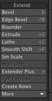
Extend
Extend is the first category of the Multiply tab, and it contains tools you’ll probably use often (Figure 1.30). The Extend tools “grow” your selection in different ways. The Extrude and Bevel tools, for example, provide different ways of “stretching” polygons into 3D shapes. The category also includes more complex tools, such as Rail Bevel (located in the More drop-down), which enable you to build a bevel from a curve placed in a background layer. When discussing layers earlier, it was mentioned that foreground and background layers are used for modeling as well as reference. Rail Bevel takes advantage of this.
Figure 1.30. The Extend category within the Multiply menu tab offers tools, such as bevel tools, to add to your objects or selections.
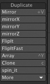
Duplicate
You might think that Duplicate tools (Figure 1.31) would be under the Modify tab, but think again! Creating a new object by mirroring, cloning, or otherwise copying another one is a form of multiplication. The Duplicate tools create variant copies of selections or objects, but these copies are not attached to your original object or selection, the way that points and polygons created with the Extend tools are.
Figure 1.31. Duplicate tools add to your object or selection by mirroring, cloning, or otherwise copying it.
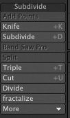
Subdivide
Ah, the Subdivide category—a deep, dark, secret set of tools that can enhance your object or selection in a variety of ways. The Subdivide tools (Figure 1.32) perform very cool operations to slice up your object or selection, add to it, or split it up in some way. Let’s say you built a cool character and soon realize that you can’t bend the character’s leg because it’s just one long “solid” object. To make the leg bend at the knee, you would use the Knife tool in this category to slice the leg and add a segment so it can bend. Another cool set of Subdivide tools is the QuickCut tools in the category’s More drop-down. These enable you to quickly slice up an object evenly, which helps you create additional detail for animation.
Figure 1.32. The Subdivide tools enable you to break up your model for added detail and animation control.
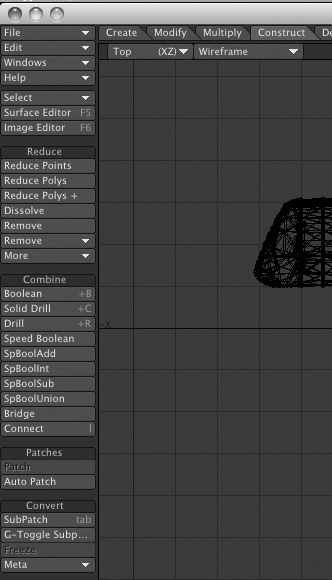
Construct Tab
When you have geometry that needs to be changed in terms of structure, you’ll work with the Construct tab. Its tools handle tasks such as Boolean operations (which you’ll perform later in the book) and reducing or converting various types of geometry. When you’re building 3D models, it’s easy to confuse the tools in the Construct tab with those in the Detail tab. The main difference between them is one of scale; when you’re working with multiple objects or sizable portions of objects, Construct is the tab you want. Use the Detail tab for fine-tuning at the level of individual points, curves, and polygons. Figure 1.33 shows the Construct tab tools.
Figure 1.33. Using the Construct tab tools, you can add points and polygons to, or subtract them from, your models.
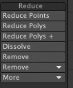
Reduce
The Reduce category contains tools that enable you to take away geometry (points or polygons) from your model without changing its appearance (Figure 1.34). Why would you do this? You could be creating a model for a video game that requires a low number of polygons for speedy animation. Or perhaps you realize you’ve overbuilt a model and added more detail than you need. Why not just leave it detailed? Simple—the more detail you have in an object, the longer it takes LightWave to calculate and render. As mentioned at the beginning of this chapter, you need to work efficiently from the ground up. Planning is key, and making models that are not too simple but not too complex is essential to 3D animation. The Reduce category enables you to reduce or remove points or polygons from models while keeping them intact with tools like Bandglue (found in the category’s More drop-down).
Figure 1.34. You can use tools in the Reduce category to decrease the number of points or polygons in an object or selection.
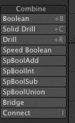
Combine
From time to time, it’s useful to merge objects or to “subtract” the shape of one object from another to create a hole or cavity. These operations, called Boolean functions, are performed using Combine tools (Figure 1.35), and they are another example of how foreground and background layers are used for modeling purposes. Typical Boolean operations involve placing an object you want to add or subtract in a background layer so that it overlaps the foreground object. LightWave v10 also features new Speed Booleans, clever tools that permit Boolean operations between objects within a single layer. The Combine tools also include Bridge, which lets you select points on two objects and “bridge” or connect them.
Figure 1.35. The Combine tools offer ways to cut holes in objects, merge and stencil objects, and bridge connections between them.
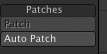
Patches
The tools in the Patches category (Figure 1.36) are useful for applying surfaces, or skins, to curves called splines. Splines are curves that can be put together in multiple ways to build objects. After you group enough curves together, you can patch them to create a surface. Think of an umbrella’s ribs as splines, and its cloth covering as a skin. Patching joins splines together and controls skin characteristics.
Figure 1.36. Use the tools in the Patches category to build a skin over a group of curves.
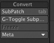
Convert
The Convert tools (Figure 1.37) turn curves into polygons, and polygons into curves—a function that’s more helpful than you might think. Let’s say you’ve built the ultimate 3D logo, using curves to surround the client’s name. All is cool until you’re ready to render it out. Curves do not render, but polygons do. So, head on over to the Convert tools and use Freeze to convert your curves into polygons. Other tools here include the popular SubPatch command, which converts three- or four-point polygons into curves, to help create smooth organic objects. There’s also the G-Toggle Subpatch, which works primarily in Layout as a way to turn a model’s subpatch subdivisions on and off. In Modeler, it works like the normal Subpatch mode, which you access by pressing the Tab key. You’ll use this feature extensively in various modeling sections of this book.
Figure 1.37. The Convert tool category within the Construct tab gives you the freedom to change—including the ability to change curves to polygons and vice versa.
Detail Tab
It’s all about the details, isn’t it? The Detail tab provides the tools that are useful for, and sometimes essential to, creating decent 3D models (Figure 1.38).
Figure 1.38. The Detail tab provides quite a few tools that let you make specific changes to points and polygons within your models.
Tools in the Detail tab are typically used to tweak a model once it’s constructed, by fine-tuning one or more points or polygons. Their specific uses include adding and removing edges from models, adjusting the “grain” or “flow” of object surfaces, and cleaning up extra points that sometimes appear along the seams where objects are merged or mirrored.
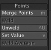
Points
Not to be confused with the Points tools in the Create tab, which are used to create points, the Detail tab’s Points tools are used to adjust point details within an existing model (Figure 1.39). For example, the Weld tool lets you reduce a cluster of points down to one, in the position of the last point you selected, and the Weld Average tool joins irregular groups of adjacent points into smooth seams. The category’s Set Value command lets you precisely reposition groups of selected points.
Figure 1.39. Tools in the Points category give you the power to control the detail of selected points within your models.
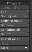
Polygons
The Detail tab’s Polygons category contains smart tools you can use to add polygons to models in spots where you need finer detail, merge polygons where you don’t, and flip or perhaps just align them (Figure 1.40). Again, these are detail controls that help you fine-tune your models. So anytime you need to make detailed, specific polygon changes, this is the place to be.
Figure 1.40. Tools in the Detail tab’s Polygons category, such as Fix Poles (found in the category’s More drop-down), give you great control over those nasty polygons.
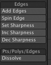
Edges
Tools in the Edges category (Figure 1.41) help you control fine polygon detail within your model or selection. The Add Edges tool, for example, lets you divide a polygon precisely by creating a new edge within it. Click a point on one edge of a selected polygon, then a point on another edge, and a new edge segment is added, connecting the clicked points. Don’t confuse this command category with the Edges button at the bottom of the Modeler interface, which is used in Edges-selection mode.
Figure 1.41. Tools for creating detailed polygon edges can be found in the Edges category of the Detail tab.
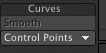
Curves
There are just a few tools in the Curves category (Figure 1.42). They enable you to quickly smooth out curves or control a curve’s start and end points. When spline modeling, for instance, you’ll probably use the Smooth function often to massage curves before skinning them, to make sure the resultant surface is clean and even.
Figure 1.42. Tools for creating details for curves can be found in the Curves category of the Detail tab.
Note
Curves and splines can be used interchangeably for many tasks, and the choice of which to use is often a matter of user preference. Note that neither curves nor splines can be rendered in Layout, so curves and splines used in model construction must be converted to polygons for final output. Splines and curves are used in Layout for motion control, modeling, and deformation.
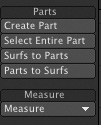
Parts and Measure
The last tool categories in the Detail tab are Parts and Measure (Figure 1.43). These categories contain several organization and measurement tools. You can select various “parts” of a model and create a part for later selection and use. In the Measure category, you can click and drag within selections for precise measurement readouts in the lower left info panel. You can measure angles, object lengths, and perimeters. But wait, there’s more! You can use other Measure tools to locate the centers of objects or create bounding-box representations, which can act as placeholders for complex objects within a model.
Figure 1.43. When you need to measure an object, find its center point, or generate a bounding-box representation, use the Measure tools.
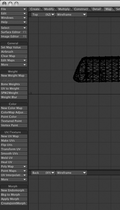
Map Tab
The Map tab is home to all the tools you’ll need for working with vertex and weight maps in Modeler. Vertex maps control attributes of vertices, or points, in your models, and LightWave uses them to characterize the weights of different objects, control morphs, and more. You’ll learn about setting these later in the book. In Figure 1.44, you can see that there are a lot of tools, but don’t worry, they’re not all used all the time, and they are easy to understand when you break them down into categories. When you begin working with vertex maps, you can edit and control them through the tools in the Map tab.
Figure 1.44. The Map tab group of tools is home to a lot of interesting commands, some of which are very powerful.
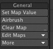
General
Multiple vertex maps may be applied to any given model, and the Map tab’s General tool category (Figure 1.45) is useful for setting or adjusting map values for any point or set of points. You can also use its Airbrush tool to create new vertex maps.
Figure 1.45. The General category of the Map tab.
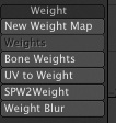
Weight
Weights are a big deal in LightWave, and not just because you gain weight sitting in front of the computer while adding weights to your 3D models. You work with weights throughout the modeling process to control the flow of curves, and you can also use them in Layout during animations. You’ll use the tools in the Weight category to create new weight maps, to apply weights to bones for character animation, and to generate weights from certain UV maps, which are described later in the Texture tool category. Figure 1.46 shows the Weight tool category.
Figure 1.46. To control weights in LightWave Modeler, head on over to the Map tab’s Weight tools.
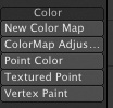
Color
Don’t confuse this category with the surface color of your object. Be aware of what you are doing and which panel and button you’re working with. You’re in the Map tab, which governs points, not the Surface Editor, which controls, well, surfaces. The Color tools within each have distinctly different applications. You use the Map tab Color tools to create color vertex maps, which you can then use for specific surface control later in Layout. These tools also include Vertex Paint, which lets you paint color onto your model’s vertices. Vertex colors blend with any polygonal surface textures you apply separately, and they are great for skin, landscapes, or just about anything. Figure 1.47 highlights the tools.
Figure 1.47. The Color category gives you access to tools that manipulate the color of an object’s vertices, or points.
Texture
Tools in the Texture category are used for creating and working with UV maps, which you can think of as the unwrapped skins of 3D models, flattened out on a grid with coordinate axes U and V. You can “paint” colors and textures onto a UV map in third-party programs such as Adobe Photoshop, and then rewrap the model with it. UVs are often used in video games because one image can be used to surface an entire object.
Did you ever put together a model car when you were a kid? Do you remember that huge sheet of stickers that you would apply to the model after building it? In a way, a UV map is like that big sheet of stickers. It’s your entire model’s texture maps, laid out. However, the map contains data unique to the specific model, and it will apply itself around the model the way you specify.
Later in this book, you’ll learn about working with UVs and create them yourself. When you do, you’ll be guided to this Texture category of the Map tab. Here, you can edit or create UVs, set UV values, and more. Figure 1.48 shows the category of tools.
Figure 1.48. The Map tab’s Texture tools don’t affect the actual surface textures of your models, but control UV maps, which “wrap around” your model and anchor at the points on its surface.
Morph
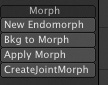
LightWave morphs are much misunderstood. People often think they change one object into another at the push of a button. In fact, a morph (technically called an endomorph) is an operation that changes the position of one or more points in an object. Moving points changes an object’s shape without adding new polygons or geometry. You’ll use morphs later in the book to make a character move. LightWave uses vertex maps to store the point-position information used in morphs, and the Map tab’s Morph tools (Figure 1.49) control those maps. Also note the M button down at the bottom right of the Modeler interface, which is where you can access any morphs that might be applied to your model.
Figure 1.49. The Morph tools within the Map tab let you change an object’s shape by repositioning points on its surface.
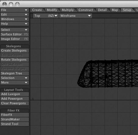
Setup Tab
This tab is where you’ll find all the necessary tools to create Skelegons. What’s a Skelegon? No, it is not an evil cartoon character (that’s Skeletor), it’s a deformation tool. Skelegons are skeletal structures that you build along with your model to define how it bends and moves. Later, when you take the model into LightWave Layout, you convert the Skelegons to bones and use them to deform and animate your object.
The Setup tab also includes tools for creating Luxigons and Powergons. Luxigons are polygons you turn into lights. Powergons are even more powerful. These are polygons to which you attach tiny command scripts, which will be executed when the model is moved into LightWave Layout for animation and rendering. You might use a Powergon to instantly add lights to a polygon for placement, like the headlights on a car. You can also define the properties for the light. Figure 1.50 shows the tab and its tools.
Figure 1.50. The Setup tab contains the tools you need for working with Skelegons as well as Luxigons and Powergons.
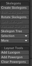
Skelegons
Naturally enough, the Skelegons category (Figure 1.51) is the area where you’ll find all the Skelegon tools. Here, you can create Skelegons, edit them, rotate them, and so on.
Figure 1.51. The Skelegons category houses all the tools you need to create and edit Skelegons, which you’ll convert to bones in the LightWave Layout application.
Layout Tools
Layout tools are the tools that you set up in Modeler whose direct effect comes to light (pun intended) in LightWave Layout. Since Layout is the portion of LightWave in which you render and see your final image, the Luxigons and Powergons tools won’t show their effects right away. Luxigons and Powergons are tools that allow you to create multiple lights and lights from polygons, for things like stage lighting, large architectural interiors, or even disco balls. John Travolta, watch out!
Because the end result of creating Luxigons and Powergons in Modeler happens in Layout, commands for creating them are found in the Layout Tools category.
FiberFX
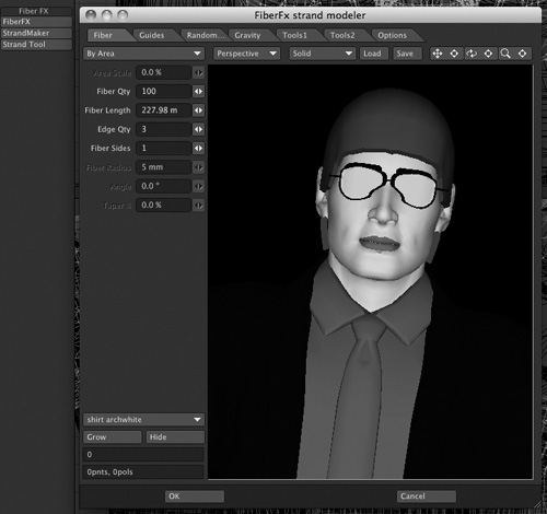
With the FiberFX category, you have access to the hair creation module in LightWave Modeler. Click the first button and a panel will open allowing you to add fibers to your 3D models, which you can later render in Layout to create hair and grass (Figure 1.52).
Figure 1.52. You can add fibers to your 3D models in the FiberFx strand modeler.
Utilities Tab
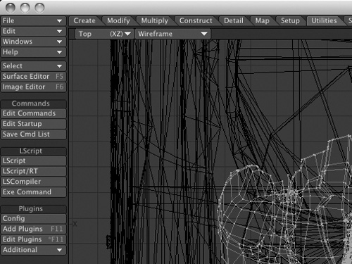
The Utilities tab contains tools for extending Modeler’s features and giving you greater control over them (Figure 1.53). These tools are used to install and access third-party plug-ins. This tab is also home within Modeler to LightWave’s custom scripting language, LScript. If you’ve added a third-party plug-in but don’t know where it went, just look at the Additional drop-down list within this tab.
Figure 1.53. The Utilities tab is home to various commands, LScript tools, and plug-in controls.
Commands
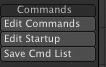
You use tools in the Commands category (Figure 1.54) to create and edit instructions, or commands, for LightWave Modeler. Say you want to always perform the same string of events on an object. You can create a custom command to do so with the Edit Commands tool. Or perhaps upon startup you want to have a Luxigon created from a ball. You can do this and much more with the Edit Startup tool.
Figure 1.54. The Commands tool category lets you create your own custom actions for Modeler.
LScript
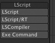
LightWave’s custom scripting language enables you to create your own plug-ins and scripts, and the tools in the LScript category (Figure 1.55) let you create scripts of your own and manage ones you make or obtain elsewhere. Even if you never write a line of script, you may need these tools occasionally in order to tweak LScripts generated automatically by other LightWave tools or plug-ins, or to compile and load LScripts you exchange with friends.
Figure 1.55. The LScript category gives you the tools to load and compile LScripts.
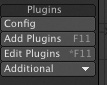
Plugins
Last in the Utilities tab is the Plugins category (Figure 1.56). Here, you can add a single plug-in or edit your existing plug-ins. You’ll also find the Additional list, which contains LightWave’s plug-ins, many of which are already assigned to buttons and keyboard equivalents with the default configuration. If you choose to add third-party plug-ins, you can find them here as well. You can also create custom buttons for those added plug-ins using the Edit Menu feature in LightWave’s Edit drop-down lists.
Figure 1.56. Use the tools in the Plugins category to manage software add-ons to LightWave.
Selection Tab
Without being able to select, you really couldn’t function in Modeler. NewTek has brought the Selection tab to LightWave 10 along with a plethora of selection tools (Figure 1.57).
Figure 1.57. The Selection tab is home to a plethora of tools to enhance your selection pleasure.

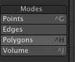
Modes
Normally only visible at the bottom of the Modeler interface, the Points, Edges, Polygons, and Volume buttons are now available in the Modes category (Figure 1.58).
Figure 1.58. If you don’t care to change selection modes at the bottom of Modeler, use this category.
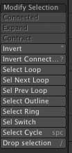
Modify Selection
Once you’ve selected some polygons, edges, or points, what are you going to do with them? Perhaps you want a different variation of your selection. If so, the tool for you might just be within the Modify Selection category. Here you can invert a selection, select an outline, select a loop, and more (Figure 1.59).
Figure 1.59. Use the Modify Selection category to change one type of selection to another.
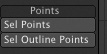
Points
The Points category allows you to select specific points within a model (Figure 1.60).
Figure 1.60. Use the Points category to select points or outline points.
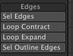
Edges
The Edges category allows you to select edges, as well as edge loops, within a model (Figure 1.61).
Figure 1.61. The Edges category allows you to select edges, loop select, or outline edges.
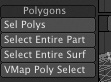
Polygons
The Polygons category allows you to select specific polygons, or parts of polygons, within a model (Figure 1.62).
Figure 1.62. The Polygons tab is where you can select polygons or parts of polygons.
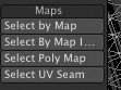
Maps
You may have created morph maps or specific weight maps within your model. If so, you can use the Maps category to select specifically mapped areas (Figure 1.63).
Figure 1.63. Use the Maps category to select any type of vertex map in Modeler.
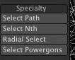
Specialty
You can use the Specialty category to select paths or Powergons within a model (Figure 1.64).
Figure 1.64. Use the Specialty category to select paths, select Powergons, and even radial select.
Selection Sets
Selection sets are often overlooked by animators, but they are quite helpful. Tools in this category (Figure 1.65) make it easy to select groups of points or polygons and combine them as selection sets. The benefit of this is twofold—not only can you easily select those same points or polygons again whenever you need them, you can also use them as specific controls in LightWave Layout.
Figure 1.65. Use the Selection Sets category to create or delete selection sets.
![]()
View Tab
Earlier in this chapter, we discussed LightWave’s viewports, but we have not yet talked about the other view options available to you. In the View tab (Figure 1.66), you’ll find many tools designed to help you maximize your modeling experience, including Magnify tools, various Layers tools, and cool selection tools.
Figure 1.66. LightWave Modeler offers a wide range of selection tools, all found under the View tab.
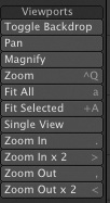
Viewports
Much of the viewport control you’ll access on a regular basis is done through the keyboard (like pressing 0 for maximize) or directly within each view. However, the Viewports tool category (Figure 1.67) gives you all those controls and more, such as Fit Selected and Fit All, as well as various zoom controls. So anytime you want to adjust what you’re seeing in your viewports, look here.
Figure 1.67. Take control of what you see with tools in the Viewports category.
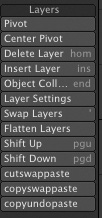
Layers
We talked about layers and the Layers panel (which you access by pressing F7) at the beginning of this chapter. The Layers tools within the View tab (Figure 1.68) complement the panel. Use these tools to add and remove layers, swap layers (foreground to background), or even flatten all layers into one. Look to this category for specific layer control in addition to the Layers panel.
Figure 1.68. Work with your layers effectively by employing the Layers category tools in the View tab.
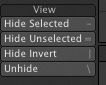
View
Last in the View tab is the View category (Figure 1.69). Use these tools to hide and unhide items you’ve selected. They’re handy when you want to work on a specific part of a model without touching neighboring parts, or to better see what you’re doing when working in Wireframe mode. Just remember that if you hide some geometry, you’ll need to unhide it again—don’t forget it’s there!
Figure 1.69. Find your way to the View category of the View tab, and you can hide or unhide selections.
So, there you have it: all the LightWave v10 Modeler menus in a quite big nutshell. Now that you understand how they are organized, when it comes time to crack them open it will be much easier to find them and to understand what they do. The next section shows you how to work more specifically with geometry in Modeler through the point and polygon selection and deselection processes.
Points, Edges, and Polygons
For everything you create in Modeler, you’ll need to select or deselect points, edges, and polygons. As mentioned earlier, you create points to make polygons. A polygon can’t exist without at least three points. (It’s like connect the dots, remember?) When points are connected to form polygons, the lines between the points become edges. With that said, take a look at Figure 1.70. Here you can see the Points, Edges, and Polygons selection and modeling modes.
Figure 1.70. At the bottom of the Modeler interface are the Points, Edges, and Polygons selection and modeling modes. Select the appropriate mode you want to work with.
![]()
Choose a selection mode by simply clicking it, or you can rotate among them by pressing the spacebar. Essentially, all you need to do is think about what you want to extend, move, rotate, and so on, and then choose the appropriate mode.
Selection Modes
Let’s say you have a project you’ve created for your best client. They come to you and say it’s great, but they would like you to move some of the model slightly. For something like this, you might want to move points, or perhaps adjust the edges. Whichever the case, selection and deselection work the same no matter what mode you’re in. This next project will help you understand further.
Exercise 1.2. Selecting and Deselecting in Modeler
Follow these steps to get a feel for selection, deselection, and the various options available to you when working with points, edges, and polygons.
- From the CH1 directory on this book’s DVD, load the Briefcase.lwo object.
- Figure 1.71 (on the next page) shows the object loaded into Modeler. Notice that the briefcase is of ordinary size. Select the Points mode at the bottom of the interface in the Back view. The Back view is the bottom-left quadrant of the interface, and looks toward the back of the object. The Back view is an XY view, meaning that you have control only over those two axes; the Z-axis is not a factor in that viewport.
Figure 1.71. The ordinary briefcase object loaded into Modeler.
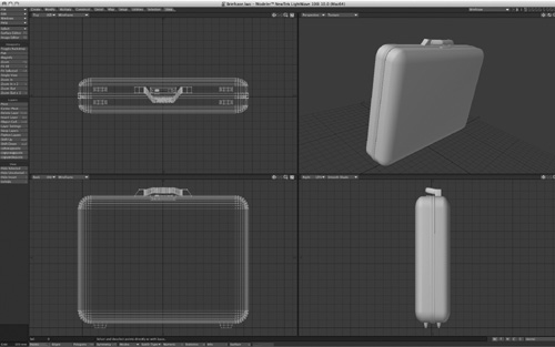
Note that you should be working with the Wireframe viewport style. Doing so will allow you to select the points in the front and back of the object. You can choose the viewport style from atop each individual viewport.
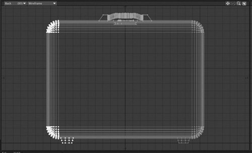
- With Points selection mode enabled, you can select points of the object. You can do this in one of two ways. The first option is to click any point directly to select it, so click around the side of the case. Your point should become highlighted as in Figure 1.72.
Figure 1.72. Directly clicking a point with the left mouse button selects it. To deselect, let go of the mouse and click again.
When you release the mouse button, you automatically enter Deselect mode. Click the point again and it will be deselected. This is exactly how the Polygons selection mode works. Now that there is nothing selected, you can begin selecting points again. If you click a point and then realize you want to select more, just hold the Shift key down and continue your selection.
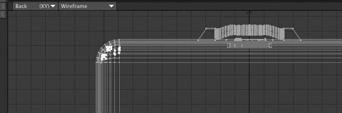
- The second option for selecting points uses Lasso select mode, which is a better choice for selecting all of the points around the side of the briefcase. Press the slash key (/) to deselect the points. With the right mouse button held down, run your mouse around the points on the side of the case, as in Figure 1.73 (on the next page).
Figure 1.73. Use the right mouse button to select a range of points in Lasso mode.
Note
Mac users, if you’re not working with a two-button mouse (even though you should be), use Control-click to accomplish right-mouse-button functions in LightWave 3D. But go get a two-button mouse already, OK?
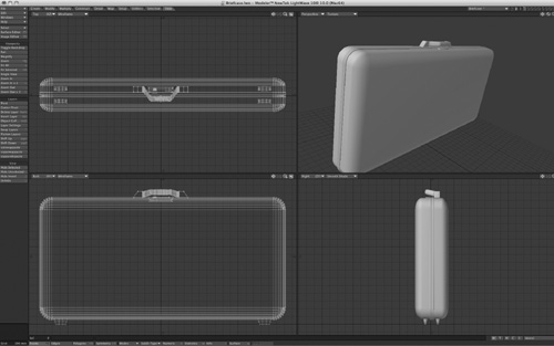
- With the points on the left side of the case selected, press t to select the Move tool from the Modify tab. Click and drag the points to the left in the Back view. You can hold the Control key as you move to constrain the movement to an axis. You can do the same to the right side, and now your ordinary briefcase is ready to carry a guitar. Figure 1.74 shows the change.
Figure 1.74. After selecting and editing just the side points of the briefcase, you now have a newly shaped object.
Congratulations! You just edited points. That’s all there is to it! After the points are adjusted to your liking, deselect them by pressing /.
Note
To properly deselect points, edges, or polygons, first turn off any tool you’re using by clicking its button in the LightWave toolset or simply press the spacebar. Then, press / to deselect. It’s important to get in the habit of performing this process. Know what you’re actually doing before you click the mouse or press a button. You can use only one tool at a time. Your process should be as follows. First, select points, edges, or polygons. Turn on a tool. Use the tool. Turn off the tool. Deselect the geometry. It sounds like a lot of steps, but learning this process will save you time in the long run.
Too often, people learning LightWave (or even those who already know it) jump the gun and forget to deselect their points or polygons and move on, only to accidentally get unwanted results in their model. And remember that the selection methods are identical whether you’re working with points, edges, or polygons.
Symmetry Mode
Every once in a while, you might find that working on the same thing twice is a real pain. Perhaps you’re building a character—why build one side of the body and then do it again for the other side? Sure, you could build half and then mirror it over. But there are times when creativity suffers because you can’t see how your entire model is coming along. If you turn on Symmetry mode, using the button to the right of the Points, Edges, and Polygons mode-selection buttons, LightWave will apply whatever action you perform on the positive X-axis on the negative X-axis as well. Note, however, that whatever point, edge, or polygon you modify on the positive X-axis must live in the same space on the negative X-axis.
Note
If you have no need for Symmetry, turn it off. Keeping it on can really mess you up because actions are mirrored across the X-axis!
Modeler General Commands
Now take a look at the rest of the buttons along the bottom of the interface, shown in Figure 1.75. Here you can see a series of buttons and tools. These are key to working in Modeler, which is why they are always visible on the interface.
Figure 1.75. The LightWave Modeler interface keeps key tools accessible along the bottom of the screen, no matter which tool tab is selected.
![]()
At the bottom left of the interface is a small information area (Figure 1.76). This is the “info” area to which I’ll refer you throughout this book. It shows you many properties, depending on the tool at hand, such as the size of objects, point position, and more.
Figure 1.76. The info area at the bottom left of the Modeler interface shows key information about your tools.
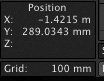
You’ll use the info area sometimes just as a reference and at other times to measure and control the movement of objects.
Modes: Action Center
To the right of the Symmetry button is another button, a drop-down list labeled Modes, which is used to set the Action Center for tools in Modeler. Settings in this list (Figure 1.77) determine how tools behave with respect to the mouse pointer, and you’ll use them often in Modeler.
Figure 1.77. The Modes selection area enables you to change how tools react to the mouse.
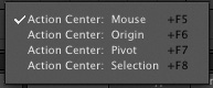
The Modes options enable you to change how certain tools work with the mouse or how their “action” is centered. The Action Center for your mouse is where a tool action happens. For example, by default the mode is set to Action Center: Mouse. This means that if you select the Rotate tool from the Modify tab, you can click and rotate in any viewport and the spot you click will be the point around which your object or selection will rotate. If you change the Action Center to say, Selection, the selected object, polygon, or point will become the center around which other objects rotate.
You’ll use these varying modes depending on what you’re creating. If you’re sizing an object within another object, it can be difficult to size perfectly in place using the Action Center: Mouse setting. Instead, set the Action Center to Selection and the Size tool works perfectly, with the object or selection sized without shifting toward the mouse location.
SubD-Type
SubD-Type stands for subdivision type. A subdivided object is one in which each polygonal patch is subdivided x number of times. You can tell Modeler (and Layout) how much subdivision to apply. The benefit of this feature is that you can create very simple geometry, manipulate it in the software, and then render it out as a detailed high-resolution model. There are two SubD-Type options in Modeler: the original Subpatch mode that existed in earlier versions of LightWave, and a new option called Catmull-Clark.
Note
The Catmull–Clark algorithm is used in computer graphics to create smooth surfaces by subdivision surface modeling. It was devised by Edwin Catmull and Jim Clark in 1978 as a generalization of bi-cubic uniform B-spline surfaces to arbitrary topology. In 2005, Edwin Catmull received an Academy Award for Technical Achievement together with Tony DeRose and Jos Stam for their invention and application of subdivision surfaces. Edwin Catmull is also the current president of Pixar.
To work in Subpatch mode, select it from the SubD-Type drop-down and press the Tab key. You’ll see your model change into curved surfaces, and a representative cage will appear around it. To revert to standard model view, press the Tab key again. In order to use the Subpatch SubD-Type, your object must have three or four vertices. That means a polygon can’t be made up of five sides or more. For that matter, it can’t be made up of one or two sides either.
Every once in a while, however, there’s no way to reduce your entire model to polygons with just three or four vertices. It’s for just those occasions that LightWave v10 added the SubD-Type called Catmull-Clark. Because this SubD-Type allows you to subdivide objects with more than three or four vertices, why even bother with the original Subpatch method at all? Backward compatibility is one reason. Those of you who have used LightWave in the past will appreciate that you can still use your existing models. Another reason is that the Catmull-Clark SubD-Type is more complex and a bit more demanding of your system resources. Applying it to one or more complex models might bring your system to its knees. That’s not to say Catmull-Clark is bad; I just recommend that you use it only when needed and not as a default.
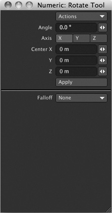
Numeric Panel
Vital to most modeling tools is the Numeric panel. Although many tools will be used just by turning them on and clicking and dragging, most tools have added control through the Numeric panel. Figure 1.78 shows the Numeric panel open with the Capsule tool selected. You can press n on your keyboard or just click the Numeric button at the bottom of the interface to open the panel.
Figure 1.78. The Numeric panel, accessible by pressing n on the keyboard or by choosing it from the bottom of the interface, is useful for specific tool control.
Note
The Numeric panel can stay open all the time. Adjust your interface to give the Numeric panel its own space on your screen. It’s useful for determining whether a tool is active. If the Numeric panel is blank, no tool is active.
Use the Numeric panel often, as both a reference and a control center for your tools.
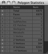
Statistics
The Statistics panel (Figure 1.79) is another key panel you should keep open. It lets you view information about your points, polygons, surfaces, and much more. You’ll employ this panel throughout the book. Note that it will change statistical information for both points and polygons based on which selection mode you’re working in. You can also use this panel to select specific surfaces you’ve set up, even subpatched polygons.
Figure 1.79. The Statistics panel, accessible from the bottom of the LightWave Modeler interface (or by pressing the w key), holds key information for points, polygons, surfaces, and more.
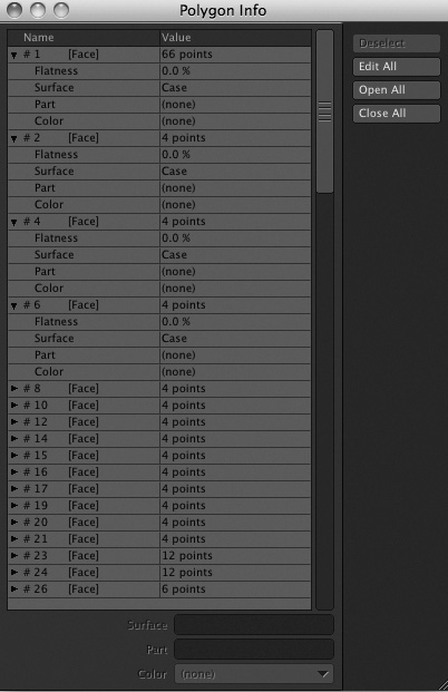
Info Panel
The Info panel (Figure 1.80) was a little-known feature in early versions of LightWave. Now you’ll find this panel at the forefront, with an access button at the bottom of the LightWave interface. This panel displays specific information about the points or polygons you have selected; the panel does not work in Edges selection mode. You can color wireframes with this panel, view surface names and groupings, and more.
Figure 1.80. The Info panel, accessible from the bottom of the Modeler interface, shows you information about point and polygon selections (but not edges).
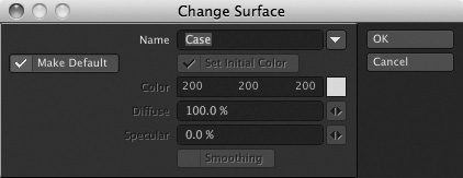
Surface
Another important button in Modeler is the Surface button, located at the bottom of the interface. Be sure not to confuse this with the Surface Editor. Clicking the Surface button opens the Change Surface requester panel, which lets you define any polygon selection as a distinct surface within your model and assign it a name and a basic color. You’ll do most of your surfacing and texturing in Layout, but you use this panel to tell LightWave that the eyeballs on your character are white, that the polygons that make up the fingernails are green, and so on. If you don’t use this panel, your object will have only one surface to which colors and textures can be applied. Figure 1.81 shows the Change Surface panel.
Figure 1.81. The Change Surface panel, accessible from the bottom of the Modeler interface (or by pressing q), enables you to name and assign colors to polygonal regions.
Make
The Make control does not have a panel but just a single button at the bottom of the Modeler interface. Say you created a few points to build an object. After laying your points down, you can click the Make button (or press the Enter key on your keyboard) to “make” the polygon.
Using and Understanding W, T, M, C, S
To the far right of the bottom of the interface is a set of tool buttons with single-letter labels W, T, M, C, and S, plus an associated drop-down list (Figure 1.82). These tools are part of LightWave’s vertex map system, and you’ll use them regularly as your work progresses in Modeler.
Figure 1.82. The W, T, M, C, and S function controls.
![]()
The vertex map tools all work in a similar fashion, but each has a different function. To use one of these tools, click its button and select New from the drop-down list to the right; the appropriate panel will appear. But what are these tools? They are simpler than you might think.
W, for Weights
The Weights tool’s main job, which we’ll discuss later in the book, is to assign information to points or polygons in your model so that you can apply specific controls later in Layout. When you’re first learning to create 3D models, you won’t have much need for these functions. However, you can apply a SubPatch Weight to subpatched objects as well to change the shape of its curves. To do this, first select the W button for Weights. Then from the drop-down list to the right, choose SubPatch Weight. Go the Map menu tab at the top of the interface, and then on the left toolbar, select the Weights tool from the Weight category. Simply click and drag a point of your subpatched object, and you can sharpen or smooth the curve. You’ll use this feature later during the modeling chapters.
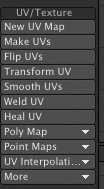
T, for Texture
The Texture mode enables you to create a new UV map for your objects. By first clicking the T button and then selecting New from the drop-down list, you can access the Create UV Map panel. UV maps are great for texturing complex objects, especially those with curves. Later in the texturing tutorials in this book, you’ll see this panel in action.
M, for Morph
Morph (or endomorph) is a powerful feature in LightWave that enables you to move a point or set of points from one position to another over time. By first clicking the M button and then choosing New from the drop-down list to the right, you’ll be able to create a new endomorph. This endomorph simply records the position of points or polygons. You can make multiple endomorphs and then use the Morph Mixer in Layout to access this data, which is saved with the object. You’ll use this feature to change the shape of an object over time, such as a character talking or a car suddenly crashing and bending.
C, for Create Vertex Color Map
Create a new color vertex map with the C button. Vertex color maps tell Modeler to label specific point (vertices) selections so you can access them in Layout to apply additional surfacing and details. If you press F8 or go to the Edit drop-down menu, you can open the Vertex Map panel and see which vertex maps are applied to your objects.
S, for Selection Set
Finally, the last button in the row at the bottom of the Modeler interface is S, for Selection Set. This handy option enables you to select any collection of points and define them as group—a selection set. It’s like taking a bunch of points you’ve selected and giving them a group name. This group name can be accessed later in Layout for things like animated dynamics, cloth, and more. It’s also handy for creating selection sets around areas of your models to create endomorphs. For example, you can create a selection set of points around the eye area of a character. By opening the Statistics panel (press w), you can quickly select this group anytime and adjust it, changing the shape of the eye for example, and then move on. This is a handy feature. Don’t confuse it with the Surface button, which affects appearance and surfacing.
Modeler Options
There’s one final area you should be aware of in LightWave Modeler: the Display Options panel (Figure 1.83), which you access by pressing d on your keyboard.
Figure 1.83. Pressing d calls up the Display Options panel, which controls settings that determine how the LightWave interface is organized.
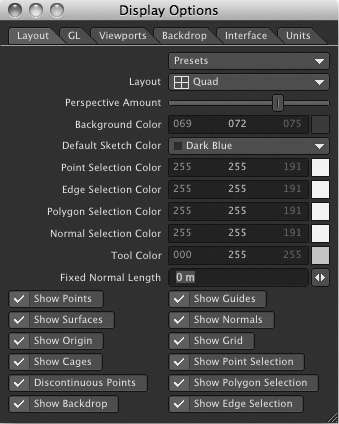
Here, you can tell Modeler to change the way the layout of the viewports looks or change what’s visible in the views. You can also use this panel to hide all your tools from view. What’s more, in this panel you can specify background images and place them in Modeler’s backdrop. Doing this enables you to work over a template, helping you build 3D models to real-world objects. You’ll do this in the character modeling section of the book. Also in the Display Options panel, you can tell Modeler to work in English, Metric, or SI. The default is SI (System International), a common unit of measurement. This book uses all default settings for tutorials.
Now, if you press o on your keyboard (that’s the letter o), you get the General Options panel (Figure 1.84). Here, you can set LightWave’s content directory as well as Subpatch level and the number of undo operations you would like.
Figure 1.84. The General Options panel lets you set the number of undos, the content directory location, and more.
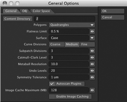
Note
The maximum number of undo operations available is 128. It’s a good idea to set this value to the max and leave it. The only reason to lower it is if you have limited system resources and are working with very large amounts of polygons. Undoing too many times on large objects can bring down even the best of systems.
Any value you set in the General Options panel will become the default once you quit Modeler because the program writes that information to LightWave’s configuration file.
The Next Step
This chapter has taken you on a tour through LightWave Modeler. And although it’s not the most exciting chapter in this book, it is a chapter you can come back to often when you ask yourself, “What was that tool for?” Throughout this chapter, I’ve noted that certain tools are used later in the book. Be sure to go through every chapter so that you can see how all these tools come together and so that you can learn just why they are included with your 3D software. There are a few other customizable areas that you should be aware of, but these tools work the same way in LightWave Layout, so we’ll cover them in that discussion. We’ll look at tools that enable you to edit your menus and set up custom keyboard shortcuts.
The next step is to take a tour of LightWave Layout in Chapter 2. (Another key new component of LightWave, CORE, will become available shortly after the release of the production and the publication of this book. You can introduce yourself to LightWave’s next generation with CORE via a bonus chapter that will be available for download in PDF form at www.danablan.com.) As the book progresses, we’ll ramp up the complexity and get you into even bigger and cooler projects.